MARS Flight Engineering Status
←
→
Page content transcription
If your browser does not render page correctly, please read the page content below
PNNL-19096

       Prepared for the U.S. Department of Energy
       Under Contract DE-AC05-76RL01830

MARS Flight Engineering Status
JE Fast, KE Dorow, SJ Morris, RC Thompson, JA Willet

November 2009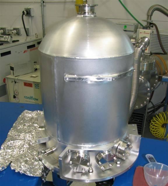
DISCLAIMER

This report was prepared as an account of work sponsored by an agency of the
United States Government. Neither the United States Government nor any agency
thereof, nor Battelle Memorial Institute, nor any of their employees, makes any
warranty, express or implied, or assumes any legal liability or responsibility
for the accuracy, completeness, or usefulness of any information, apparatus,
product, or process disclosed, or represents that its use would not infringe
privately owned rights. Reference herein to any specific commercial product,
process, or service by trade name, trademark, manufacturer, or otherwise does not
necessarily constitute or imply its endorsement, recommendation, or favoring by
the United States Government or any agency thereof, or Battelle Memorial
Institute. The views and opinions of authors expressed herein do not necessarily
state or reflect those of the United States Government or any agency thereof.

            PACIFIC NORTHWEST NATIONAL LABORATORY
                               operated by
                               BATTELLE
                                  for the
              UNITED STATES DEPARTMENT OF ENERGY
                   under Contract DE-AC05-76RL01830

                        Printed in the United States of America

                    Available to DOE and DOE contractors from the
                     Office of Scientific and Technical Information,
                        P.O. Box 62, Oak Ridge, TN 37831-0062;
                                     ph: (865) 576-8401
                                    fax: (865) 576-5728
                              email: reports@adonis.osti.gov

        Available to the public from the National Technical Information Service,
       U.S. Department of Commerce, 5285 Port Royal Rd., Springfield, VA 22161
                                    ph: (800) 553-6847
                                    fax: (703) 605-6900
                             email: orders@ntis.fedworld.gov
                    online ordering: http://www.ntis.gov/ordering.htm

                        This document was printed on recycled paper.
                                          (9/2003)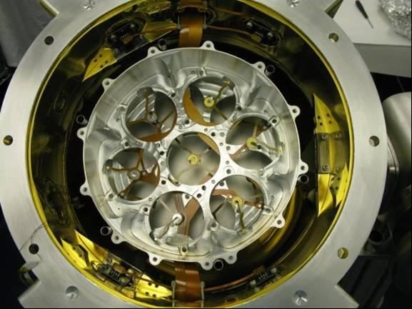
PNNL-19096

MARS Flight Engineering Status

JE Fast, KE Dorow, SJ Morris, RC Thompson, JA Willet

November 2009

Prepared for
the U.S. Department of Energy
under Contract DE-AC05-76RL01830

Pacific Northwest National Laboratory
Richland, Washington 99352
PNNL-19096

                                            Abstract

    The Multi-sensor Airborne Radiation Survey Flight Engineering project (MARS FE) has designed a
high purity germanium (HPGe) crystal array for conducting a wide range of field measurements. In
addition to the HPGe detector system, a platform-specific shock and vibration isolation system and
environmental housing have been designed to support demonstration activities in a maritime environment
on an Unmanned Surface Vehicle (USV). This report describes the status of the equipment as of the end
of FY09.

                                                  iii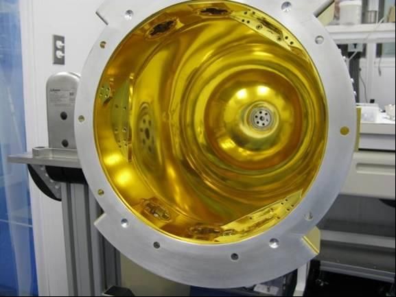
PNNL-19096

                                   Executive Summary

     This document describes the status of the MARS Flight Engineering demonstration system. The
MARS Flight Engineering project is developing a field demonstration unit as a second spiral development
of the MARS Technology – a high-efficiency, compact, field-ready high purity germanium (HPGe) array.
An initial laboratory prototype system was designed, built and tested under the MARS R&D project.
This second spiral includes modifications to the design based on lessons learned in the laboratory
prototype, additional engineering analysis, and focus on a specific deployment platform – the SPARTAN
unmanned surface vehicle (USV), a rigid hull inflatable watercraft. In addition to the HPGe detector
module, the MARS Flight project is designing and building a platform-specific environmental enclosure
with shock and vibration isolation for the HPGe detector unit and the electronics crate.

    The field demonstration system design is complete and all of the system components, with the
exception of the environmental housing, have been delivered or fabricated. Initial dry fit assembly is
underway and some vacuum testing is completed. The complete HPGe system is expected to be
assembled by the end of fiscal year 2009. The environmental enclosure and vibration isolation system
should be available in late January, 2010 for integration tests with the SPARTAN USV. Complete
system integration and testing is scheduled for February/March, continuing up to the initial demonstration
activity in Charleston, SC in May 2010.

                                                    v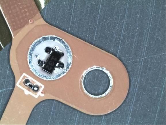
PNNL-19096

                                                                      Contents

Abstract ........................................................................................................................................................ iii
Executive Summary ...................................................................................................................................... v
1.0 Introduction .......................................................................................................................................... 9
2.0 System Status........................................................................................................................................ 9
        2.1 Gamma Detection Subsystem ...................................................................................................... 9
                2.1.1 Detector Electronics Assembly ......................................................................................... 2
                2.1.2 Detector Crystal Assembly ................................................................................................ 2
                2.1.3 Cryostat – Detector Enclosure ........................................................................................... 5
        2.2 Environmental Enclosure and Vibration Isolation Subsystem ..................................................... 8
        2.3 Data Acquisition Subsystem ...................................................................................................... 10
        2.4 MARS Graphical User Interface (GUI) Software Module......................................................... 11
        2.5 Summary .................................................................................................................................... 13

                                                                                vii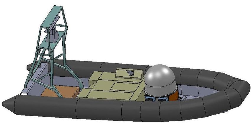
PNNL-19096

                                                                    Figures

Figure 1: MARS Flight Engineering System Block Diagram. ..................................................................... 2
Figure 2: Detail of Front End circuit on flex cable. Component in circular area is the FET.
     Component to the below and to the right of the FET is the feedback resistor. Capacitors are
     built in to the circuit layout using the Kapton dielectric. The hole on the right is used to
     secure the flexible interconnect to the aluminum spool. ....................................................................... 3
Figure 3: Front end circuit after installation of lid over FET. The lid encloses the warm (~120-
     150 K) FET to prevent thermal radiation from hitting adjacent HPGe detectors that need to
     operate at ≤90K. .................................................................................................................................... 3
Figure 4: Spool assemblies with Kapton flexible interconnects installed. .................................................... 4
Figure 5: Detector Crystal Assembly mounted in Cryostat. ......................................................................... 4
Figure 6: Vacuum cryostat prior to gold plating. .......................................................................................... 5
Figure 7: Liquid nitrogen Dewar. Bellows tube at top seals to top of cryostat and provides a fill
     port. Vertical legs are grade 5 Titanium supports that provide excellent mechanical strength
     with low thermal conductivity. Tank is being wired with silicon diode temperature sensors. ............ 6
Figure 8: Cryostat after "Lasergold" plating. Several feedthroughs can be seen around the
     chamber (upper-right to lower-left): HPGe signal, high voltage, silicon diode temperature
     monitors, vacuum port. ......................................................................................................................... 7
Figure 9: Interior of vacuum cryostat showing Lasergold plating. ............................................................... 7
Figure 10: Thin domed window. This window is only 1 mm thick (aluminum) in order to
     maximize sensitivity to low energy gamma-rays for applications that require this sensitivity. ........... 8
Figure 11: MARS vibration isolation and environmental enclosure without dome and side panels. ........... 9
Figure 12: MARS system deployed in a Spartan watercraft ....................................................................... 10
Figure 13: Compact PCI crate. This is the rugged crate from Dawn VME. The power supplies on
     the right are hot-swappable. The board next to the power supplies is the general purpose
     acquisition board that reads out the state-of-health data from silicon diode temperature
     sensors and feedback voltages from the preamplifiers. The four matching boards near the
     middle are the high voltage supplies for the HPGe detectors. The four matching boards
     towards the left are the MCA modules from XIA, Inc. The embedded processor and crate
     controller are located on the far left. ................................................................................................... 11
Figure 14: End user interface. ..................................................................................................................... 12

                                                                           viii
PNNL-19096
1.0 Introduction
This document describes the status of the MARS Flight Engineering demonstration system. The
MARS Flight Engineering project is developing a field demonstration unit as a second spiral development
of the MARS Technology – a high-efficiency, compact, field-ready high purity germanium (HPGe) array.
An initial laboratory prototype system was designed, built and tested under the MARS R&D project.
This second spiral includes modifications to the design based on lessons learned in the laboratory
prototype, additional engineering analysis, and focus on a specific deployment platform – the SPARTAN
unmanned surface vehicle (USV), a rigid hull inflatable watercraft. In addition to the HPGe detector
module, the MARS Flight project is designing and building a platform-specific environmental enclosure
with shock and vibration isolation for the HPGe detector unit and the electronics crate.
The field demonstration system design is complete and all of the system components, with the
exception of the environmental housing, have been delivered or fabricated. Initial dry fit assembly is
underway and some vacuum testing is completed. The complete HPGe system is expected to be
assembled by the end of fiscal year 2009. The environmental enclosure and vibration isolation system
should be available in late January, 2010 for integration tests with the SPARTAN USV. Complete
system integration and testing is scheduled for February/March, continuing up to the initial demonstration
activity in Charleston, SC in May 2010.
2.0 System Status
Figure 1 shows the MARS system components, as well as additional components such as neutron
detectors that would form a complete Integrated Radiation Detection System. The MARS Flight
Engineering project scope includes the MARS System (white boxes) plus the platform-specific enclosure,
vibration isolation and graphical user interface (GUI) software for the SPARTAN demonstration (tan
boxes). Status of the various components and sub-systems is provided below.
2.1 Gamma Detection Subsystem
The Gamma Detection Subsystem represents the main hardware components that house the HPGe
detectors and the associated analog electronics. All of these components have been delivered or
fabricated.
ixPNNL-19096
Legend
Various
Not part of MARS Platform
Inspection Platforms Dependent
Flight Project
For MARS Flight
System
demonstration only
Configuration
On-Platform MARS Item of MARS
Flight Project (Temporary Entries,
Graphical User Interface Questions &
Integrated Radiation Detection (IRD) System Comments)
(multiple platform configurations
& may contain one or more MARS systems)
Long-term Analysis Data
Archive Hardware Unit
(TBD Option)
Neutron Detector
Multi-sensor Airborne Multiple Platform Multiple Platform
(Other Sensors) IRD Enclosures/
Radiation Survey MARS Vibration
System
Pods Isolation Assemblies
(MARS) System (dependent on (dependent on
platform platform & IRD
configurations) configurations)
Data Acquisition MARS Graphical User Gamma
Subsystem Interface (GUI) Software Detection
(DAQ) (SW) Module Subsystem MARS Flight Field-test
(Control & Operator GUI) Platform Enclosure
(may be integrated
Detector Electronics
Data Acquisition Assembly
with vibration
Assembly End-User Interface
SW Module isolation assembly)
Detector Crystal
Assembly
Power Unit
Expert-User Interface
SW Module MARS Flight Field-test
Cryostat - Detector Vibration Isolation
Enclosure
MARS Flight Assembly
Field-test Host
Hardware Operational
For MARS GUI Configuration Items Operational CIs
(CIs) TBD
SW Module TBD
Figure 1: MARS Flight Engineering System Block Diagram.
2.1.1 Detector Electronics Assembly
The Detector Electronics Assembly, also referred to as the “saddle bags”, mounts to the outside of the
cryostat and houses preamplifiers and high voltage filters. All of the components are on hand and the first
unit has been fully assembled. The second unit remains to be assembled and complete testing requires
integration with the cryostat assembly.
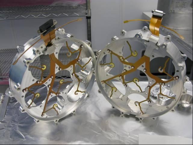
2.1.2 Detector Crystal Assembly
The Detector Crystal Assembly, also known as the “spool assembly”, houses the HPGe crystals and the
Kapton flexible cable interconnect that carries high voltage to the detectors and the signals from the
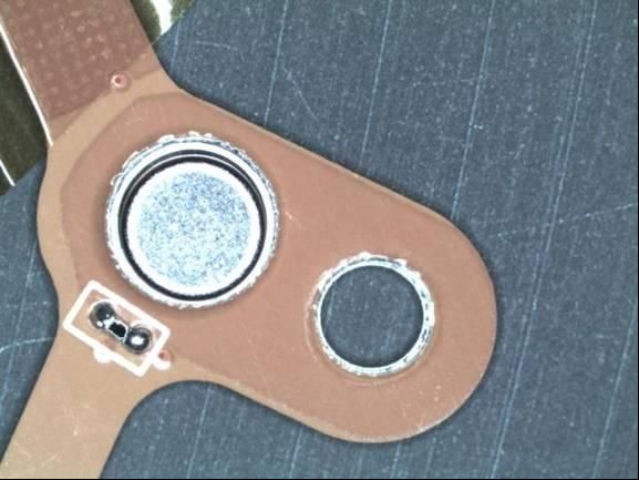
detectors out to the vacuum feedthroughs to the Detector Electronics Assembly. The flexible circuits
have integrated front end electronics (FET, feedback resistor, test input capacitor) for each detector
channel (Figure 2, Figure 3). The spool assemblies are completed and the flexible interconnects mounted,
but the HPGe detectors are not yet installed (Figure 4). The spools have been fitted into the cryostat
(Figure 5) and are undergoing vacuum processing (pump and bake) to reduce outgassing prior to
introduction of the HPGe.
2PNNL-19096
Figure 2: Detail of Front End circuit on flex cable. Component in circular area is the FET. Component to
the below and to the right of the FET is the feedback resistor. Capacitors are built in to the circuit layout
using the Kapton dielectric. The hole on the right is used to secure the flexible interconnect to the
aluminum spool.
Figure 3: Front end circuit after installation of lid over FET. The lid encloses the warm (~120-150 K)
FET to prevent thermal radiation from hitting adjacent HPGe detectors that need to operate at ≤90K.
3PNNL-19096
Figure 4: Spool assemblies with Kapton flexible interconnects installed.
Figure 5: Detector Crystal Assembly mounted in Cryostat.
4PNNL-19096
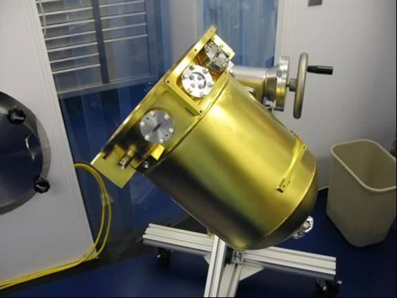
2.1.3 Cryostat – Detector Enclosure
The HPGe detectors are operated at cryogenic temperatures (~90 K) inside a vacuum cryostat. The
assembly consists of the main vacuum vessel, a liquid nitrogen dewar, and a vacuum window. These
parts were fabricated by Atlas Technologies in Port Townsend, WA who have unique capabilities in
aluminum vacuum chamber manufacturing; including bi-metallic joints that enable them to join stainless
steel conflate flanges to aluminum chambers. The main vacuum vessel is shown in Figure 6 during final
vacuum testing at the vendor. The liquid nitrogen dewar is shown in Figure 7. The Dewar holds about 6
liters of liquid nitrogen and is omni-directional, i.e. the liquid will remain in the Dewar independent of the
orientation of the assembly.
Heat transfer from the warm exterior walls of the cryostat to the liquid nitrogen cooled inner dewar and
Detector Crystal Assembly is primarily from radiation. In order to minimize this heat transfer the warm
surfaces are plated with very low emissivity gold (Epner Technologies, Inc. Lasergold). The plated
cryostat is shown in Figure 8 and Figure 9. The thin, domed window is shown in Figure 10. It is
designed to be minimal thickness for low-energy gamma ray sensitivity.
Figure 6: Vacuum cryostat prior to gold plating.
5PNNL-19096
Figure 7: Liquid nitrogen Dewar. Bellows tube at top seals to top of cryostat and provides a fill port.
Vertical legs are grade 5 Titanium supports that provide excellent mechanical strength with low thermal
conductivity. Tank is being wired with silicon diode temperature sensors.
6PNNL-19096
Figure 8: Cryostat after "Lasergold" plating. Several feedthroughs can be seen around the chamber
(upper-right to lower-left): HPGe signal, high voltage, silicon diode temperature monitors, vacuum port.
Figure 9: Interior of vacuum cryostat showing Lasergold plating.
7PNNL-19096
Figure 10: Thin domed window. This window is only 1 mm thick (aluminum) in order to maximize
sensitivity to low energy gamma-rays for applications that require this sensitivity.
2.2 Environmental Enclosure and Vibration Isolation Subsystem
The environmental enclosure consists of a radome-type structure which encloses the MARS system and a
support frame to house the associated electronics and support equipment. The environmental enclosure
will be EMI shielded to provide a reduced RF environment for the MARS system to operate. It will also
provide a thermally controlled environment for the system.
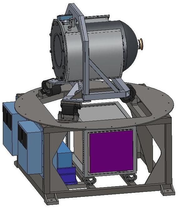
The MARS cryostat will be mounted in a vibration isolation framework. The framework and the coil
spring isolators will absorb the majority of the shock and vibration of the Spartan platform. The cryostat
mounted within the vibration isolation frame is shown in Figure 11.
The environmental enclosure and vibration isolation frame has been designed and is out for competitive
bid. The environmental enclosure is shown mounted in the Spartan in Figure 12.
8PNNL-19096
Figure 11: MARS vibration isolation and environmental enclosure without dome and side panels.
9PNNL-19096
Figure 12: MARS system deployed in a Spartan watercraft
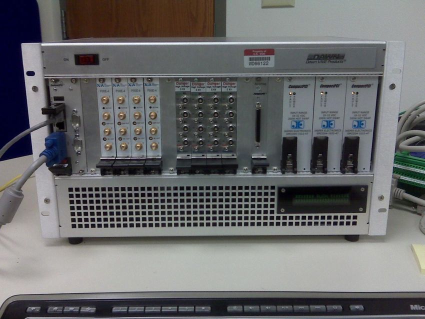
2.3 Data Acquisition Subsystem
The data acquisition system resides in a 19” wide 3U high compact-PCI chassis, shown in Figure 13. The
system contains an embedded controller running Linux that controls the crate and runs the data
acquisition and analysis software. Four 4-channel high voltage cards provide the bias voltage for the
HPGe detectors. These are a PNNL design capable of operating up to 5 kV. The HPGe signals are
processed using four PIXIE-4 multi-channel analyzer (MCA) boards from XIA, Inc that digitize the
pulses from the detectors. These cards are configurable to store a variety of information from just the
time-stamped pulse heights for normal operations up to the full digitized waveforms for debugging and
development of advanced pulse shape analysis algorithms. The silicon diode temperature sensor signals
are amplified on a signal conditioning board immediately outside the vacuum cryostat and then read out
with a commercial data acquisition board in the c-PCI crate. The complete data acquisition system is
assembled and has been tested using the MARS R&D cryostat. The initial ruggedized c-PCI chassis had
a backplane problem that prevented proper configuration of the PIXIE-4 cards (master-slave
configuration). The crate was reworked by the vendor and has been successfully tested. Parts are on
hand for two complete systems so that laboratory development and demonstration activities can occur
concurrently. This also provides for a complete spare system for the demonstration activities (e.g. should
there be an incident in shipping).
10PNNL-19096
Figure 13: Compact PCI crate. This is the rugged crate from Dawn VME. The power supplies on the
right are hot-swappable. The board next to the power supplies is the general purpose acquisition board
that reads out the state-of-health data from silicon diode temperature sensors and feedback voltages from
the preamplifiers. The four matching boards near the middle are the high voltage supplies for the HPGe
detectors. The four matching boards towards the left are the MCA modules from XIA, Inc. The
embedded processor and crate controller are located on the far left.
The data acquisition system also includes the operational software that runs on the embedded controller to
collect and analyze the data. The basic data collection software is complete and tested. The analysis
software is still under development, but most of the key elements are in place, including peak finding and
fitting routines and semi-automated calibration routines. The main outstanding elements are isotope
identification and alarming routines and advanced routines such as directionality or advanced
characterization (e.g. Pu-600 code). The isotope ID and alarming routines will be built around well-
developed algorithms that have been used for several projects at PNNL. Work is underway to develop
directionality algorithms using data collected with the MARS R&D detector. Additional analysis tools
will be incorporated as time and budget permit.
2.4 MARS Graphical User Interface (GUI) Software Module
The MARS software consists of two aspects, the data collection and analysis software that reside in the
embedded controller of the data acquisition system (server) and the GUI that the operator will use to
interact with the system (client). The GUI can run either on the embedded computer or on a remote host
platform. The GUI is Java based and can run under a variety of operating systems, including Windows
and Unix/Linux systems. Data is passed from the server to the client via standard TCPIP protocol.
11PNNL-19096
The user interface is designed for a variety of user levels, including “basic” operators, “advanced”
operators who would be familiar with gamma ray spectroscopy, and “system developers” who would
configure and calibrate the system. The latter would be typical of a service depot operator in a deployed
system. The user interface developed for the SPARTAN USV demonstration is shown in Figure 14. The
upper left area provides red light/green light system status indicators. The graphic to the right of that
shows an overhead view of the SPARTAN USV and an indicator of the direction of the detected radiation
(implementation of an algorithm to provide this data is pending). The upper right area provides a list of
alarms, including time, isotope, confidence level, type of source (medical, industrial, threat, etc.). The
operator can select any alarm and bring up the gamma ray spectrum that triggered the alarm which will
show the raw spectrum and overlays of the fitted peaks. The lower left area is a graph of radiation level
(at the instrument) versus time; or the operator can toggle to view the current gamma ray spectra for any
of several time intervals. The lower right area provides count rate versus time for specific isotopes. The
isotopes presented in this region are user configurable.
Advanced user interfaces include control panels to adjust high voltage, monitor feedback voltages (related
to detector leakage currents), turn individual channels on and off, etc. Other settings that configure the
PIXIE-4 MCA boards are also available via these control panels. These settings include gain, decimation,
threshold, coincidence masks etc.
The software is built with a flexible design allowing analysis algorithms to be added as further
development occurs. The architecture allows for real-time user configuration of analysis routines without
recompiling code.
Figure 14: End user interface.
12PNNL-19096
2.5 Summary
The MARS Flight Engineering project is developing a field demonstration unit as a second spiral
development of the MARS Technology. An initial laboratory prototype system was designed, built and
tested under the MARS R&D project. This second spiral includes modifications to the design based on
lessons learned in the laboratory prototype, additional engineering analysis, and focus on a specific
deployment platform – the SPARTAN unmanned surface vehicle, a rigid hull inflatable watercraft.
Significant emphasis has been placed on developing a graphical user interface suitable for the target end-
user skill sets. Both the hardware and software are progressing well and are on track for the field
demonstration in May, 2010.
13You can also read