QUANTUM EFFICIENCY ENHANCEMENT OF A GAN-BASED GREEN LIGHT-EMITTING DIODE BY A GRADED INDIUM COMPOSITION P-TYPE INGAN LAYER - MDPI
←
→
Page content transcription
If your browser does not render page correctly, please read the page content below

nanomaterials

Article
Quantum Efficiency Enhancement of a GaN-Based
Green Light-Emitting Diode by a Graded Indium
Composition p-Type InGaN Layer
Quanbin Zhou 1       ID
                          , Hong Wang 1,2, *, Mingsheng Xu 1,2 and Xi-Chun Zhang 1, *
 1   Engineering Research Center for Optoelectronics of Guangdong Province, School of Electronics and
     Information Engineering, South China University of Technology, Guangzhou 510640, China;
     zhouquanbin86@163.com (Q.Z.); mshxu@163.com (M.X.)
 2   School of Physics and Optoelectronics, South China University of Technology, Guangzhou 510640, China
 *   Correspondence: phhwang@scut.edu.cn (H.W.); xchzhang@scut.edu.cn (X.-C.Z.);
     Tel.: +86-136-0006-6193 (H.W.)

 Received: 27 May 2018; Accepted: 7 July 2018; Published: 9 July 2018

 Abstract: We propose a graded indium composition p-type InGaN (p-InGaN) conduction layer to
 replace the p-type AlGaN electron blocking layer and a p-GaN layer in order to enhance the light
 output power of a GaN-based green light-emitting diode (LED). The indium composition of the
 p-InGaN layer decreased from 10.4% to 0% along the growth direction. The light intensity of the LED
 with a graded indium composition p-InGaN layer is 13.7% higher than that of conventional LEDs
 according to the experimental result. The calculated data further confirmed that the graded indium
 composition p-InGaN layer can effectively improve the light power of green LEDs. According to the
 simulation, the increase in light output power of green LEDs with a graded indium composition
 p-InGaN layer was mainly attributed to the enhancement of hole injection and the improvement of
 the radiative recombination rate.

 Keywords: p-type InGaN; graded indium composition; hole injection; quantum efficiency; green LED

1. Introduction
      GaN-based light-emitting diodes (LEDs) have attracted considerable attention and have been seen
as a promising replacement for conventional light sources in the last few decades [1,2]. The efficiency of
blue LEDs is very high, and blue LEDs have been commercially used in many fields, such as lighting [3–6],
display [7,8], light communication [9,10], back lighting [11,12], and so on. However, the internal
quantum efficiency (IQE) of GaN-based green LEDs is still lower than that of blue LEDs, which is
called the “Green Gap” [13]. It obstructs the green LED to be applied in Red-Green-Blue (RGB)
lighting, full-color displays, and visible-light communication. A large polarization field [14–16] and
poor crystal quality [17,18] are the main reasons for the low IQE of green LEDs with a high indium
composition. In fact, the poor hole injection also plays an important role in the low quantum efficiency
of GaN-based LEDs. Many researchers have proposed various methods to solve this problem based
on band engineering of the electron blocking layer (EBL). Kim et al. employed an active-layer-friendly
lattice-matched InAlN EBL to improve the quantum efficiency of green LEDs [19]. A graded superlattice
AlGaN/GaN inserting layer was proposed by J. Kang et al. to enhance the efficiency of hole
injection and performance of green LEDs [20]. An InAlGaN/GaN superlattice [21], an AlGaN/InGaN
superlattice [22,23], and a composition-graded AlGaN EBL [24–26] were also employed to reduce the
potential barrier of holes without damaging the electron confinement. A recently proposed method
to improve the properties of p-type GaN is polarization doping [27]. It uses the internal polarization

Nanomaterials 2018, 8, 512; doi:10.3390/nano8070512                     www.mdpi.com/journal/nanomaterials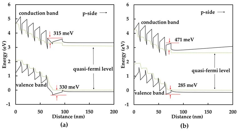
Nanomaterials 2018, 8, 512 2 of 8
Nanomaterials 2018, 8, x FOR PEER REVIEW 2 of 8
ofuses
the structures
the internal and material composition
polarization of the structures grading andtomaterial
induce free electronsgrading
composition or holesto [28]. However,
induce free
the growth temperature of AlGaN is always high in order to
electrons or holes [28]. However, the growth temperature of AlGaN is always high in orderimprove the crystal quality. The high
to
indium
improve content InGaN/GaN
the crystal quality. Themultiple quantum
high indium well (MQW)
content InGaN/GaN of green LEDsquantum
multiple will be damaged
well (MQW) during
of
the highLEDs
green temperature
will be process
damaged [29–32].
duringTherethe high are few reports about
temperature the [29–32].
process p-type layerTherestructure
are few designed
reports
toabout
improve the hole
the p-type injection
layer of GaN-based
structure designed to LEDsimprove [33]. the hole injection of GaN-based LEDs [33].
InInthis paper,
this paper,wewe designed
designeda new structure
a new structure of p-type InGaN
of p-type (p-InGaN)
InGaN (p-InGaN)conduction layer with
conduction layerawith
gradeda
gradedcomposition
indium indium composition
to replace to thereplace the conventional
conventional p-type AlGaN p-type AlGaN EBL
(p-AlGaN) (p-AlGaN)
and p-type EBLGaN and (p-GaN)
p-type
GaN (p-GaN)
conduction layerconduction
of GaN-based layer of GaN-based
green LEDs. The effect greenofLEDs. The effect
the graded indium of composition
the graded p-InGaN indium
composition
conduction layerp-InGaN conduction
on the light output powerlayer on the light
of green LEDs output power
is studied of green LEDs
by experiments andissimulations.
studied by
experiments and simulations.
2. Experimental Details
2. Experimental Details
The LED samples were grown on (0001)-oriented sapphire substrates by an AIXTRON close-coupled
The LED
showerhead samples were
metal-organic grown vapor
chemical on (0001)-oriented
deposition (MOCVD) sapphire substrates by an AIXTRON
reactor (MOCVD, AIXTRON close-
Inc.,
coupled showerhead
Herzogenrath, Germany).metal-organic
The trimethylgalliumchemical(TMGa), vapor trimethylaluminum
deposition (MOCVD) (TMAl), reactor (MOCVD,
trimethylindium
AIXTRON
(TMIn), Inc., Herzogenrath,
and ammonia (NH3 ) were Germany).
used as sources The trimethylgallium
of gallium, aluminum,(TMGa),indium, trimethylaluminum
and nitrogen,
(TMAl), trimethylindium
respectively. Silane (SiH4 ) (TMIn), and ammonia (NH
and bicyclopentadienyl 3) were used
magnesium as 2sources
(Cp Mg) were of gallium,
used asaluminum,
n-type and
indium, and nitrogen, respectively. Silane (SiH
p-type doping sources, respectively. The epitaxial structure of conventional LEDs consistedMg)
4 ) and bicyclopentadienyl magnesium (Cp 2 of a were
30 nm
thick GaN nucleation layer grown at 530 C, a 3 µm thick undoped GaN (u-GaN) buffer layer LEDs
used as n-type and p-type doping sources, ◦ respectively. The epitaxial structure of conventional grown
atconsisted
1100 ◦ C, ofa 4aµm
30 nmthickthick GaN nucleation
Si-doped n-type GaN layer grown layer
(n-GaN) at 530with
°C, a83×µm 10thick
18 cmundoped
–3 dopingGaN (u-GaN)
concentration
bufferatlayer
grown 1080grown
◦ C, five atpairs
1100of°C, a 4 µm
3 nm and thick
10 nmSi-doped
thick In0.22n-type
Ga0.78GaN
N/GaN(n-GaN)MQWs layer withlayers,
active 8 × 10¹⁸ cmnm
a 20
–3
doping
thick p-typeconcentration
Al0.15 Ga0.85 grown at 1080 °C,
N (p-AlGaN) five pairs
electron of 3 nm
blocking and grown
layer 10 nm thick
at 1040In0.22 Gaand
◦ C, 0.78N/GaN MQWs
a 180 nm thick
active layers, a 20 nm thick p-type Al
p-GaN layer grown at 940 ◦ C. The doping concentration of the p-AlGaN and p-GaNatlayers
0.15Ga 0.85 N (p-AlGaN) electron blocking layer grown 1040 °C,
was
and a18180 nm –3 thick p-GaN layer grown at 940 °C. The doping concentration of the p-AlGaN and p-
5 × 10 cm . The conventional LEDs were denoted as sample A. Figure 1a is the profile of sample A.
GaN layers was 5 × 1018 cm–3. The conventional LEDs were denoted as sample A. Figure 1a is the
We also prepared green LEDs with a graded indium composition p-InGaN conduction layer, which are
profile of sample A. We also prepared green LEDs with a graded indium composition p-InGaN
denoted as sample B. The growth conditions of sample B were similar to that of sample A except for
conduction layer, which are denoted as sample B. The growth conditions of sample B were similar to
the p-type layers. As shown in Figure 1b, the p-AlGaN and p-GaN layers were replaced by a p-InGaN
that of sample A except for the p-type layers. As shown in Figure 1b, the p-AlGaN and p-GaN layers
single layer with a thickness of 200 nm. The growth temperature of p-InGaN layer was 860 ◦ C, and the
were replaced by a p-InGaN single layer with a thickness of 200 nm. The growth temperature of p-
flow of TMIn changed from 175 sccm to 0 sccm along the growth direction in order to obtain a p-InGaN
InGaN layer was 860 °C, and the flow of TMIn changed from 175 sccm to 0 sccm along the growth
layer with a graded indium composition. Furthermore, we grew another sample with only a p-InGaN
direction in order to obtain a p-InGaN layer with a graded indium composition. Furthermore, we
film on u-GaN in order to determine the indium composition of the p-InGaN layer. The TMIn flow of
grew another sample with only a p-InGaN film on u-GaN in order to determine the indium
the p-InGaN film
composition remained
of the p-InGaN atlayer.
175 sccm,
The TMInand the flowgrowth
of thetemperature
p-InGaN filmwas 860 ◦ C.atFigure
remained 175 sccm,1c shows
and thethe
schematic diagram of the p-InGaN film, which is denoted as sample
growth temperature was 860 °C. Figure 1c shows the schematic diagram of the p-InGaN film, which C. The thickness of the p-InGaN
layer in sample
is denoted C was C.
as sample 80 The
nm.thickness of the p-InGaN layer in sample C was 80 nm.
Figure 1. Schematic
Figure diagrams
1. Schematic for the
diagrams forLED
the and
LEDp-InGaN samples:
and p-InGaN (a) sample
samples: A; (b)A;sample
(a) sample B; andB;(c)
(b) sample andsample
(c) C.
sample C.
After the growth of the LED structure of sample A and sample B, the epitaxial wafers were treated
After
together the growth
to LED of the
chips. The LED wafers
epitaxial structure of first
were sample A and
cleaned sample B,
in acetone, the epitaxial
isopropanol, wafers were
deionized water,
treated together to LED chips. The epitaxial wafers were first cleaned in acetone, isopropanol,
and partly etched to n-GaN by an inductively coupled plasma (ICP) system. Next, these samples were
deionized water, and partly etched to n-GaN by an inductively coupled plasma (ICP) system. Next,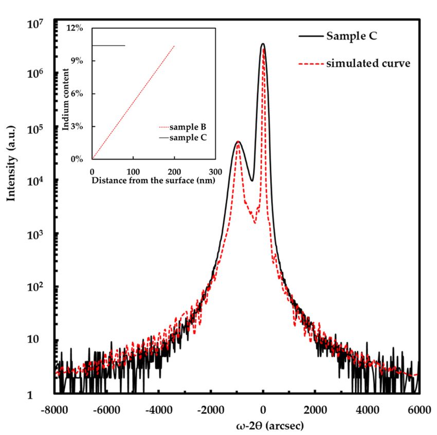
Nanomaterials 2018, 8, x FOR PEER REVIEW                                                                             3 of 8
Nanomaterials 2018, 8, 512                                                                                           3 of 8
these samples were cleaned by a sulfuric acid peroxide mixture at 60 °C, ammonia water at 35 °C,
deionized water at room temperature, and dried by nitrogen gas. Sequentially, the 80 nm indium tin
cleaned  by atransparent
              sulfuric acidconductive
                            peroxide mixture   at 60  ◦ C, ammonia water at 35 ◦ C, deionized water at room
oxide  (ITO)                           electrodes  (TCEs)   were evaporated by electron beam evaporation
temperature,
and            and dried
     then annealed   at 600by°C
                              nitrogen  gas.inSequentially,
                                for 3 min      a mixture ofthe   80 nmN
                                                              ambient   indium    tin oxide (ITO) transparent
                                                                          2/O2 (200:35). The ITO TCEs were
conductiveremoved
selectively  electrodesby(TCEs)  were evaporated
                           wet chemical               by electron
                                          etching. Then,    the SiObeam  evaporation and then annealed at
                                                                    2 passivation layer was deposited by a
600 ◦ C for 3 min in a mixture of ambient N /O (200:35). The ITO TCEs were selectively removed by
plasma enhanced chemical vapor deposition      2   (PECVD)
                                                    2          system. Finally, Cr (50 nm)/Al (200 nm)/Ti
wet chemical
(100           etching.
     nm)/Au (100    nm)Then,   the SiO
                         electrode     2 passivation
                                   layers              layer was
                                          were deposited         deposited
                                                             by electron     by aevaporation.
                                                                          beam     plasma enhanced   chemical
                                                                                               The size of the
vapor  deposition  (PECVD)   system.
LED chip was 1.14 mm × 1.14 mm.       Finally, Cr (50  nm)/Al  (200  nm)/Ti  (100  nm)/Au   (100 nm) electrode
layers were deposited by electron beam evaporation. The size of the LED chip was 1.14 mm × 1.14 mm.
3. Results and Discussion
3. Results and Discussion
      We characterized the crystallography of the p-InGaN film in sample C by a Rigaku high-
      We characterized the crystallography of the p-InGaN film in sample C by a Rigaku high-resolution
resolution X-ray diffraction (XRD, Rigaku Inc., Tokyo, Japan) with Cu Kα irradiation at 40 kV and 100
X-ray diffraction (XRD, Rigaku Inc., Tokyo, Japan) with Cu Kα irradiation at 40 kV and 100 mA. Figure 2
mA. Figure 2 is the HRXRD ω-2θ scan of p-InGaN film in sample C. The main peak and the secondary
is the HRXRD ω-2θ scan of p-InGaN film in sample C. The main peak and the secondary peak are
peak are GaN and InGaN, respectively. Chen et al. and Zhou et al. calculated the indium composition
GaN and InGaN, respectively. Chen et al. and Zhou et al. calculated the indium composition of the
of the InxGa1−xN film using Vegard’s law and the XRD data [34–36]. We evaluated the indium content
In Ga1−x N film using Vegard’s law and the XRD data [34–36]. We evaluated the indium content of
of xthe p-InGaN film by the separation between GaN and InGaN peaks in the XRD spectra. The indium
the p-InGaN film by the separation between GaN and InGaN peaks in the XRD spectra. The indium
content of p-InGaN in sample C was 10.4%. No evidence of phase separation could be found in the
content of p-InGaN in sample C was 10.4%. No evidence of phase separation could be found in the
XRD spectrum. When the indium content is not too high, it almost linearly increases as the TMIn flow
XRD spectrum. When the indium content is not too high, it almost linearly increases as the TMIn
increasing [37]. Because the p-InGaN in sample B had similar growth conditions to sample C, except
flow increasing [37]. Because the p-InGaN in sample B had similar growth conditions to sample C,
for the TMIn flow changing form 175 sccm to 0 sccm, the indium content in p-InGaN of sample B was
except for the TMIn flow changing form 175 sccm to 0 sccm, the indium content in p-InGaN of sample
from 10.4% to 0% along the growth direction. The expected indium content profiles of samples B and
B was from 10.4% to 0% along the growth direction. The expected indium content profiles of samples
C are shown in the inset of Figure 2.
B and C are shown in the inset of Figure 2.

      Figure  2. High-resolution
      Figure 2.  High-resolutionX-ray
                                   X-ray  diffraction
                                       diffraction    ω-2θ
                                                   ω-2θ scanscan  of sample
                                                             of sample  C. TheC. The dashed
                                                                               dashed          line
                                                                                      line in red    in red
                                                                                                  is the    is the
                                                                                                         simulated
      simulated  curve. The  inset shows  the  indium content  profiles of samples
      curve. The inset shows the indium content profiles of samples B and C.       B and   C.

     The light output properties of the two LED samples are shown in Figure 3. Figure 3a shows the
      The light output properties of the two LED samples are shown in Figure 3. Figure 3a shows the
light output power as a function of injection current. Sample B had a great enhancement of light
light output power as a function of injection current. Sample B had a great enhancement of light output
output power for the whole injection current range compared with the sample A. The light output
power for the whole injection current range compared with the sample A. The light output power of
power of sample B was 13.7% larger than that of sample A at a 300 mA injection current. The result
Nanomaterials 2018, 8, 512                                                                                           4 of 8
 Nanomaterials 2018, 8, x FOR PEER REVIEW                                                                        4 of 8

sample
 revealedB was  13.7%
           that the     larger
                    graded     than that
                             indium        of sample
                                     composition        A at a 300
                                                      p-InGaN       mA injection
                                                                conduction        current.
                                                                            layer was        The result
                                                                                       beneficial       revealed
                                                                                                  for enhancing
that the graded   indium   composition    p-InGaN     conduction   layer was  beneficial
 the light output power of a GaN-based green LED. It is clear that the peak intensity    for enhancing   the light
                                                                                                               of
output  power of a GaN-based
 electroluminescence              green
                         (EL) spectra    LED.
                                      at 300 mA It is
                                                   ofclear that
                                                      sample  B the
                                                                 waspeak  intensity
                                                                     stronger       of electroluminescence
                                                                               than that of sample A, as shown(EL)
spectra at 300
 in Figure  3b.mA   of sample Bthe
                 Furthermore,    waspeak
                                       stronger   than that of
                                            wavelengths     of sample
                                                               samplesA,Aasandshown  in Figure
                                                                                 B were   529 nm3b. and
                                                                                                    Furthermore,
                                                                                                        534 nm
the peak  wavelengths
 respectively.            of samples  A  and  B  were   529 nm   and 534 nm   respectively.

      Figure3.3.Light
     Figure           output
                  Light      properties
                         output           of samples
                                 properties           A and A
                                               of samples    B: (a)
                                                                 andmeasured light output
                                                                      B: (a) measured     power
                                                                                        light   and enhancement
                                                                                              output  power and
     percentage
      enhancement as apercentage
                      function of as
                                  thea injection
                                        function current; (b) measured
                                                  of the injection        EL(b)
                                                                    current; spectra at 300EL
                                                                                measured    mA; and (c)
                                                                                              spectra atcalculated
                                                                                                         300 mA;
     EL spectra
      and        at 300 mA.
          (c) calculated  EL spectra at 300 mA.

      InInorder
            order   to better
                 to better    understand
                           understand        the influence
                                       the influence        of the indium
                                                     of the graded  graded composition
                                                                             indium composition    p-InGaN
                                                                                         p-InGaN conduction
 conduction
layer            layer on the ofperformance
        on the performance        GaN-based of     GaN-based
                                                green  LEDs, wegreen   LEDs, awe
                                                                  performed         performed
                                                                                 numerical     a numerical
                                                                                            simulation using
 simulation    using  APSYS   software  (version 2010, Crosslight Software  Inc., Burnaby,
APSYS software (version 2010, Crosslight Software Inc., Burnaby, BC, Canada). The software BC, Canada). The
 software    self-consistently solves the Poisson  equation, continuity equation,  and Schrödinger
self-consistently solves the Poisson equation, continuity equation, and Schrödinger equation with  equation
 with boundary conditions [38,39]. Here, the band-offset ratio between the conduction band and the
boundary conditions [38,39]. Here, the band-offset ratio between the conduction band and the valence
 valence band for InGaN/GaN MQWs was 70% [40]. In addition, the values of the Shockley-Read-Hall
band for InGaN/GaN MQWs was 70% [40]. In addition, the values of the Shockley-Read-Hall
 (SRH) recombination lifetime and Auger coefficients assumed in this simulation were 50 ns and 1 ×
(SRH) recombination lifetime and Auger coefficients assumed in this simulation were 50 ns and
 10−30 cm6/s, respectively [41–43]. Figure 3c displays the calculated EL spectra at 300 mA, which shows
1 × 10⁻³⁰ cm6 /s, respectively [41–43]. Figure 3c displays the calculated EL spectra at 300 mA,
 a similar trend of enhancement in light intensity with measured results. The simulated energy band
which shows a similar trend of enhancement in light intensity with measured results. The simulated
 diagrams at 300 mA of sample A and sample B are shown in Figure 4. The solid lines are conduction
energy band diagrams at 300 mA of sample A and sample B are shown in Figure 4. The solid lines
 bands and valence bands and the dashed lines are the quasi-fermi level. In sample A, the height of
are conduction bands and valence bands and the dashed lines are the quasi-fermi level. In sample A,
 the barrier, which obstructs holes injecting into the MQW, is 330 meV. However, in sample B, the
the height of the barrier, which obstructs holes injecting into the MQW, is 330 meV. However, in sample
 height of the barrier is 285 meV when the p-AlGaN EBL and p-GaN conduction layer are replaced by
B, the height of the barrier is 285 meV when the p-AlGaN EBL and p-GaN conduction layer are replaced
 the graded indium composition p-InGaN conduction layer. The lower potential barrier is beneficial
by the graded indium composition p-InGaN conduction layer. The lower potential barrier is beneficial
 for holes injecting into the MQW.
for holes injecting into the MQW.
      Figure 5 plots the carrier concentration distribution and radiation recombination rate distribution
in the MQW of sample A and sample B from n-side to p-side. The holes of samples A and B both
accumulate in the quantum well near the p-type layer. As shown in Figure 5a, the hole concentration
in the quantum well near the p-type layer of sample B was much larger than that of sample A.
The function of the EBL is to reduce the electron overflow leakage. Therefore, sample A had a little
more electron concentration in the MQW, as shown in Figure 5b. The higher carrier concentration led
to a larger radiation recombination rate of GaN-based LED. From Figure 5c, we could find that the
radiation recombination rate of sample B was much bigger than that of sample A in the quantum well
near the p-type layer. As a result, sample B had a higher total radiation recombination rate compared to
sample A. The simulation data demonstrated that the graded indium composition p-InGaN conduction
layer could enhance the hole injection and radiation recombination rate of GaN-based green LEDs.
Nanomaterials 2018, 8, 512                                                                                       5 of 8
 Nanomaterials 2018, 8, x FOR PEER REVIEW                                                                         5 of 8

            Figure 4. Calculated energy band diagrams at 300 mA of (a) sample A; and (b) sample B.

     Figure 5 plots the carrier concentration distribution and radiation recombination rate
distribution in the MQW of sample A and sample B from n-side to p-side. The holes of samples A
and B both accumulate in the quantum well near the p-type layer. As shown in Figure 5a, the hole
concentration in the quantum well near the p-type layer of sample B was much larger than that of
sample A. The function of the EBL is to reduce the electron overflow leakage. Therefore, sample A
had a little more electron concentration in the MQW, as shown in Figure 5b. The higher carrier
concentration led to a larger radiation recombination rate of GaN-based LED. From Figure 5c, we
could find that the radiation recombination rate of sample B was much bigger than that of sample A
in the quantum well near the p-type layer. As a result, sample B had a higher total radiation
recombination rate compared to sample A. The simulation data demonstrated that the graded indium
composition p-InGaN conduction layer could enhance the hole injection and radiation recombination
            Figure4.4.Calculated
           Figure
rate of GaN-based     green      energy
                             LEDs.
                      Calculated  energyband
                                         banddiagrams
                                              diagramsatat300
                                                           300mA
                                                              mAofof(a)
                                                                     (a)sample
                                                                         sampleA;
                                                                                A;and
                                                                                   and(b)
                                                                                       (b)sample
                                                                                           sampleB.B.

      Figure 5 plots the carrier concentration distribution and radiation recombination rate
 distribution in the MQW of sample A and sample B from n-side to p-side. The holes of samples A
 and B both accumulate in the quantum well near the p-type layer. As shown in Figure 5a, the hole
 concentration in the quantum well near the p-type layer of sample B was much larger than that of
 sample A. The function of the EBL is to reduce the electron overflow leakage. Therefore, sample A
 had a little more electron concentration in the MQW, as shown in Figure 5b. The higher carrier
 concentration led to a larger radiation recombination rate of GaN-based LED. From Figure 5c, we
 could find that the radiation recombination rate of sample B was much bigger than that of sample A
 in the quantum well near the p-type layer. As a result, sample B had a higher total radiation
 recombination rate compared to sample A. The simulation data demonstrated that the graded indium
 composition p-InGaN conduction layer could enhance the hole injection and radiation recombination
 rate of GaN-based green LEDs.
     Figure 5. (a) Hole concentration distribution; (b) electron concentration distribution; and (c) radiation
     recombination
     recombination rate
                     rate distribution
                          distribution of
                                       of samples
                                          samples A
                                                  A and
                                                     and B.
                                                          B.

4. Conclusions
     In conclusion, the light output properties of GaN-based green LEDs with and without a graded
                                              numerically and
indium composition p-InGaN layer were numerically          and experimentally
                                                                experimentally investigated.
                                                                                 investigated. Both the
experimental results and simulated data revealed that that the
                                                            the graded
                                                                graded indium
                                                                        indium composition
                                                                                 composition p-InGaN
                                                                                               p-InGaN
conduction layer
conduction  layer can
                  can promote
                      promote the
                                the light
                                    light output
                                          output power
                                                 power of
                                                       of green
                                                          green LEDs.
                                                                 LEDs. The light output power of green
LEDs with a p-InGaN conduction layer was enhanced by 13.7% compared to the conventional LED,
according to the experimental data. The simulation results demonstrated that the improvement in light
output property was mainly due to the increase of hole injection and the enhancement of the radiative
recombination rate.

AuthorFigure   5. (a) HoleConceptualization,
          Contributions:                      Q.Z. and(b)
                          concentration distribution;   H.W.;  Dataconcentration
                                                          electron  curation, Q.Z.; Formal analysis,
                                                                                  distribution; and (c)Q.Z. and M.X.;
                                                                                                        radiation
Investigation,  Q.Z.;  Methodology, Q.Z. and  H.W.;  Supervision,
        recombination rate distribution of samples A and B.         X.-C.Z.; Writing—original   draft, Q.Z. and M.X.,
Q.Z. designed the experiment, prepared the samples, performed the measurements and the simulation, and wrote
the manuscript. H.W. contributed to the conception of the study and designed the experiment. M.X. contributed
to4.the
     Conclusions
        data analysis and wrote the manuscript. X.-C.Z. supervised the study and reviewed the manuscript.
Funding:  This researchthe
      In conclusion,     was  funded
                           light      by the
                                  output     Nationalof
                                          properties High  Technology
                                                        GaN-based     Research
                                                                    green LEDsand  Development
                                                                                with  and withoutProgram
                                                                                                    a gradedof
China (No. 2014AA032609), in part by the National Natural Science Foundation of China (No. 61504044), the Key
 indium composition
Technologies R&D Programs p-InGaN    layer were
                                of Guangdong      numerically
                                              Province          and experimentally
                                                        (Nos. 2014B0101119002,       investigated.
                                                                               2017B010112003), the Both
                                                                                                    Appliedthe
 experimental results and simulated data revealed that the graded indium composition p-InGaN
 conduction layer can promote the light output power of green LEDs. The light output power of green
Nanomaterials 2018, 8, 512 6 of 8
technologies R&D Projects of Guangdong Province (Nos. 2015B010127013, 2016B010123004), the technologies
R&D Programs of Guangzhou City (Nos. 201504291502518, 201604046021), and the Science and Technology
Development Special Fund Projects of Zhangshan City (Nos. 2017F2FC0002, 2017A1009).
Conflicts of Interest: The authors declare no conflict of interest.
References
1. Wang, L.; Liu, Z.; Zhang, Z.H.; Tian, Y.D.; Yi, X.; Wang, J.; Li, J.; Wang, G. Interface and photoluminescence
characteristics of graphene-(GaN/InGaN)n multiple quantum wells hybrid structure. J. Appl. Phys. 2016,
119, 611–622. [CrossRef]
2. Wang, Q.; Ji, Z.; Zhou, Y.; Wang, X.; Liu, B.; Xu, X.; Gao, X.; Leng, J. Diameter-dependent photoluminescence
properties of strong phase-separated dual-wavelength InGaN/GaN nanopillar LEDs. Appl. Surf. Sci. 2017,
410, 196–200. [CrossRef]
3. Pimputkar, S.; Speck, J.S.; Denbaars, S.P.; Nakamura, S. Prospects for LED lighting. Nat. Photonics 2009, 3,
180–182. [CrossRef]
4. Sinnadurai, R.; Khan, M.K.A.A.; Azri, M.; Vikneswaran, V. Development of White LED down Light for
Indoor Lighting. In Proceedings of the IEEE Conference on Sustainable Utilization and Development in
Engineering and Technology (STUDENT), Kuala Lumpur, Malaysia, 6–9 October 2012; pp. 242–247.
5. Moon, S.; Koo, G.B.; Moon, G.W. A new control method of interleaved single-stage flyback AC–DC converter
for outdoor LED lighting systems. IEEE Trans. Power Electron. 2013, 28, 4051–4062. [CrossRef]
6. Poulet, L.; Massa, G.D.; Morrow, R.C.; Bourget, C.M.; Wheeler, R.M.; Mitchell, C.A. Significant reduction in
energy for plant-growth lighting in space using targeted LED lighting and spectral manipulation. Life Sci.
Space Res. 2014, 2, 43–53. [CrossRef]
7. Sanchot, A.; Consonni, M.; Calvez, S.L.; Robin, I.C.; Templier, F. Color conversion using quantum dots on
high-brightness GaN LED arrays for display application. MRS Proc. 2015, 1788, 19–21. [CrossRef]
8. Lee, K.J. Flexible GaN LED on a polyimide substrate for display applications. Proc. SPIE 2012, 8268, 52.
9. Ferreira, R.; Xie, E.; Mckendry, J.; Rajbhandari, S. High bandwidth GaN-based micro-LEDs for multi-Gb/s
visible light communications. IEEE Photonics Technol. Lett. 2016, 28, 2023–2026. [CrossRef]
10. Du, C.; Huang, X.; Jiang, C.; Pu, X.; Zhao, Z.; Jing, L.; Hu, W.; Wang, Z.L. Tuning carrier lifetime in
InGaN/GaN LEDs via strain compensation for high-speed visible light communication. Sci. Rep. 2016, 6,
37132. [CrossRef] [PubMed]
11. Anandan, M. Progress of LED backlights for LCDS. J. Soc. Inf. Displ. 2008, 16, 287–310. [CrossRef]
12. Soon, C.M. White Light Emitting Diode as Liquid Crystal Display Backlight; Massachusetts Institute of
Technology: Cambridge, MA, USA, 2007.
13. Zhou, Q.; Xu, M.; Wang, H. Internal quantum efficiency improvement of InGaN/GaN multiple quantum
well green light-emitting diodes. Opto-Electron. Rev. 2016, 24, 1–9. [CrossRef]
14. Young, N.G.; Farrell, R.M.; Iza, M.; Nakamura, S.; DenBaars, S.P.; Weisbuch, C.; Speck, J.S. Germanium doping
of GaN by metalorganic chemical vapor deposition for polarization screening applications. J. Cryst. Growth
2016, 455, 105–110. [CrossRef]
15. Prajoon, P.; Nirmal, D.; Menokey, M.A.; Pravin, J.C. Efficiency enhancement of InGaN MQW LED using
compositionally step graded InGaN barrier on SiC substrate. J. Disp. Technol. 2016, 12, 1117–1121. [CrossRef]
16. Xu, M.; Yu, W.; Zhou, Q.; Zhang, H.; Wang, H. Efficiency enhancement of GaN-based green light-emitting
diode with PN-doped quantum barriers. Mater. Express 2016, 6, 533–537. [CrossRef]
17. Ren, P.; Zhang, N.; Xue, B.; Liu, Z.; Wang, J.; Li, J. A novel usage of hydrogen treatment to improve the indium
incorporation and internal quantum efficiency of green InGaN/GaN multiple quantum wells simultaneously.
J. Phys. D Appl. Phys. 2016, 49, 175101. [CrossRef]
18. Qiao, L.; Ma, Z.-G.; Chen, H.; Wu, H.-Y.; Chen, X.-F.; Yang, H.-J.; Zhao, B.; He, M.; Zheng, S.-W.; Li, S.-T.
Effects of multiple interruptions with trimethylindium-treatment in the InGaN/GaN quantum well on green
light emitting diodes. Chin. Phys. B 2016, 25, 107803. [CrossRef]
19. Kim, H.J.; Choi, S.; Kim, S.-S.; Ryou, J.-H.; Yoder, P.D.; Dupuis, R.D.; Fischer, A.M.; Sun, K.; Ponce, F.A.
Improvement of quantum efficiency by employing active-layer-friendly lattice-matched InAlN electron
blocking layer in green light-emitting diodes. Appl. Phys. Lett. 2010, 96, 101102. [CrossRef]Nanomaterials 2018, 8, 512 7 of 8
20. Kang, J.; Li, H.; Li, Z.; Liu, Z.; Ma, P.; Yi, X.; Wang, G. Enhancing the performance of green GaN-based
light-emitting diodes with graded superlattice AlGaN/GaN inserting layer. Appl. Phys. Lett. 2013, 103, 102104.
[CrossRef]
21. Lin, D.-W.; Tzou, A.-J.; Huang, J.-K.; Lin, B.-C.; Chang, C.-Y.; Kuo, H.-C. Greatly improved efficiency droop
for InGaN-based green light emitting diodes by quaternary content superlattice electron blocking layer.
In Proceedings of the International Conference on Numerical Simulation of Optoelectronic Devices (NUSOD),
Taipei, Taiwan, 7–11 September 2015; pp. 15–16.
22. Yu, C.-T.; Lai, W.-C.; Yen, C.-H.; Chang, S.-J. Effects of ingan layer thickness of AlGaN/InGaN superlattice
electron blocking layer on the overall efficiency and efficiency droops of GaN-based light emitting diodes.
Opt. Express 2014, 22, A663–A670. [CrossRef] [PubMed]
23. Chen, F.-M.; Liou, B.-T.; Chang, Y.-A.; Chang, J.-Y.; Kuo, Y.-T.; Kuo, Y.-K. Numerical Analysis of Using
Superlattice-AlGaN/InGaN as Electron Blocking Layer in Green InGaN Light-Emitting Diodes; International
Society for Optics and Photonics: Bellingham, WA, USA, 2013; pp. 862526–862527.
24. Lei, Y.; Liu, Z.; He, M.; Yi, X.; Wang, J.; Li, J.; Zheng, S.; Li, S. Enhancement of blue InGaN light-emitting
diodes by using AlGaN increased composition-graded barriers. J. Semicond. 2015, 36, 054006. [CrossRef]
25. Wang, C.H.; Ke, C.C.; Lee, C.Y.; Chang, S.P. Hole injection and efficiency droop improvement in InGaN/GaN
light-emitting diodes by band-engineered electron blocking layer. Appl. Phys. Lett. 2010, 97, 261103. [CrossRef]
26. Kuo, Y.K.; Chang, J.Y.; Tsai, M.C. Enhancement in hole-injection efficiency of blue InGaN light-emitting
diodes from reduced polarization by some specific designs for the electron blocking layer. Opt. Lett. 2010, 35,
3285–3287. [CrossRef] [PubMed]
27. Kivisaari, P.; Oksanen, J.; Tulkki, J. Polarization doping and the efficiency of III-nitride optoelectronic devices.
Appl. Phys. Lett. 2013, 103, 1029. [CrossRef]
28. Li, S.; Zhang, T.; Wu, J.; Yang, Y.; Wang, Z.; Wu, Z.; Chen, Z.; Jiang, Y. Polarization induced hole doping in
graded Alx Ga1−x N (x = 0.7~1) layer grown by molecular beam epitaxy. Appl. Phys. Lett. 2013, 102, 132103.
[CrossRef]
29. Oh, M.S.; Kwon, M.K.; Park, I.K.; Baek, S.H.; Park, S.J.; Lee, S.H.; Jung, J.J. Improvement of green LED
by growing p-GaN on In0.25 GaN/GaN MQWs at low temperature. J. Cryst. Growth 2006, 289, 107–112.
[CrossRef]
30. Lee, W.; Limb, J.; Ryou, J.H.; Yoo, D.; Chung, T.; Dupuis, R.D. Influence of growth temperature and growth
rate of p-GaN layers on the characteristics of green light emitting diodes. J. Electron. Mater. 2006, 35, 587–591.
[CrossRef]
31. Lee, W.; Limb, J.; Ryou, J.H.; Yoo, D.; Chung, T.; Dupuis, R.D. Effect of thermal annealing induced by p-type
layer growth on blue and green LED performance. J. Cryst. Growth 2006, 287, 577–581. [CrossRef]
32. Ju, J.W.; Zhu, J.; Kim, H.S.; Lee, C.R.; Lee, I.H. Effects of p-GaN growth temperature on a green InGaN/GaN
multiple quantum well. J. Korean Phys. Soc. 2007, 50, 810. [CrossRef]
33. Lin, Z.; Wang, H.; Lin, Y.; Yang, M.; Li, G.; Xu, B. A new structure of p-GaN/InGaN heterojunction to enhance
hole injection for blue GaN-based LEDs. J. Phys. D Appl. Phys. 2016, 49, 285106. [CrossRef]
34. Qin, Z.; Chen, Z.; Tong, Y.; Lu, S.; Zhang, G. Estimation of InN phase inclusion in InGaN films grown by
MOVPE. Appl. Phys. A 2002, 74, 655–658. [CrossRef]
35. Chen, Z.Z.; Qin, Z.X.; Hu, X.D.; Yu, T.J.; Yang, Z.J.; Tong, Y.Z.; Ding, X.M.; Zhang, G.Y. Study of photoluminescence
and absorption in phase-separation InGaN films. Phys. B Condens. Matter 2004, 344, 292–296. [CrossRef]
36. Zhou, S.Q.; Wu, M.F.; Hou, L.N.; Yao, S.D.; Ma, H.J.; Nie, R.; Tong, Y.Z.; Yang, Z.J.; Yu, T.J.; Zhang, G.Y. An
approach to determine the chemical composition in InGaN/GaN multiple quantum wells. J. Cryst. Growth
2004, 263, 35–39. [CrossRef]
37. Guo, Y.; Liu, X.L.; Song, H.P.; Yang, A.L.; Xu, X.Q.; Zheng, G.L.; Wei, H.Y.; Yang, S.Y.; Zhu, Q.S.; Wang, Z.G.
A study of indium incorporation in In-rich InGaN grown by MOVPE. Appl. Surf. Sci. 2010, 256, 3352–3356.
[CrossRef]
38. Apsys, Version 2010 Software for Electrical, Optical and Thermal Properties of Compound Semiconductor Devices;
Crosslight Software Inc.: Burnaby, BC, Canada, 2010.
39. Zhao, H.; Arif, R.A.; Ee, Y.K.; Tansu, N. Self-consistent analysis of strain-compensated InGaN-AlGaN
quantum wells for lasers and light-emitting diodes. IEEE J. Quantum Electron. 2008, 45, 66–78. [CrossRef]Nanomaterials 2018, 8, 512 8 of 8
40. Li, J.; Guo, Z.; Li, F.; Lin, H.; Li, C.; Xiang, S.; Zhou, T.; Wan, N.; Liu, Y. Performance enhancement of blue
light-emitting diodes by using special designed n and p-type doped barriers. Superlattices Microstruct. 2015,
85, 454–460. [CrossRef]
41. Zhang, M.; Yun, F.; Li, Y.; Ding, W.; Wang, H.; Zhao, Y.; Zhang, W.; Zheng, M.; Tian, Z.; Su, X. Luminescence
properties of InGaN-based dual-wavelength light-emitting diodes with different quantum-well arrangements.
Phys. Status Solidi 2015, 212, 954–959. [CrossRef]
42. Cheng, L.; Wu, S.; Chen, H.; Xia, C.; Kong, Q. Investigation of whether uniform carrier distribution in
quantum wells can lead to higher performance in InGaN light-emitting diodes. Opt. Quantum Electron. 2016,
48, 1–9. [CrossRef]
43. Piprek, J. Efficiency droop in nitride-based light-emitting diodes. Phys. Status Solidi 2010, 207, 2217–2225.
[CrossRef]
© 2018 by the authors. Licensee MDPI, Basel, Switzerland. This article is an open access
article distributed under the terms and conditions of the Creative Commons Attribution
(CC BY) license (http://creativecommons.org/licenses/by/4.0/).You can also read