AN5439 Application note - Augmented NDEF with ST25DV-I2C series Dynamic NFC Tags
←
→
Page content transcription
If your browser does not render page correctly, please read the page content below

AN5439
                                                                       Application note
       Augmented NDEF with ST25DV-I2C series Dynamic NFC Tags

             Introduction
             The purpose of this application note is to explain how a microcontroller can enhance the
             ST25DV-I2C series Dynamic NFC Tags to provide an augmented NDEF experience to end-
             users.
             NDEF message (NFC data exchange format) is stored in the ST25DV-I2C series Dynamic
             NFC Tags and read by any NFC Forum compatible device. NDEF message contains various
             information, such as URI, text, images, Bluetooth® connection information.
             When reading the NDEF message, NFC Forum compatible smartphones automatically
             trigger specific actions, without the requirement of an external application, such as, opening
             the web browser for an NDEF message containing a URL, or automatically performing
             Bluetooth pairing.
             The content of NDEF message in an NFC Forum tag that is usually static. It is modified by
             an NFC Forum reader or a smartphone but it does not automatically change on external
             events.
             However, it is interesting to dynamically update the content of an NDEF message upon
             external or internal events. For example, embed dynamic information in an URL to
             automatically redirect the user to a personalized web page, or embed sensors data into an
             SMS or e-mail to automatically send sensors’ data when tapping the tag, These actions are
             performed without the requirement of an additional application thanks to Android™ and iOS
             native support of NDEF message reading.
             The term augmented NDEF stands for an NDEF message stored in an NFC Forum tag
             whose content is dynamically modified by the tag to provide additional information.
             This application note applies to the ST25DV-I2C series Dynamic NFC Tags and is now
             referred to as ST25DV-I2C.

April 2020                                    AN5439 Rev 2                                             1/27
                                                                                                  www.st.com   1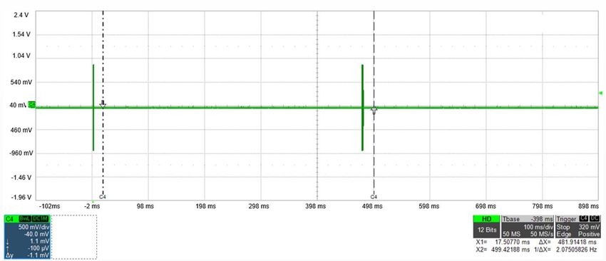
Contents                                                                                                       AN5439

Contents

1          Overview . . . . . . . . . . . . . . . . . . . . . . . . . . . . . . . . . . . . . . . . . . . . . . . . . . 5

2          Augmented NDEF content update . . . . . . . . . . . . . . . . . . . . . . . . . . . . . . 6
           2.1      Automatic NDEF content update on phone detection . . . . . . . . . . . . . . . . 6
                    2.1.1       Arbitration between RF and I2C interfaces in ST25DV-I2C . . . . . . . . . . . 6
                    2.1.2       NDEF detection and reading procedure in smartphones . . . . . . . . . . . . . 7
                    2.1.3       Timing constraints for automatic NDEF content update . . . . . . . . . . . . 11
                    2.1.4       Battery-less automatic NDEF content update implementation . . . . . . . 12
                    2.1.5       Battery powered automatic NDEF content update implementation . . . . 18
           2.2      Periodical NDEF content update and update based on external events . 24
           2.3      Configuration data considerations . . . . . . . . . . . . . . . . . . . . . . . . . . . . . . 25

3          Revision history . . . . . . . . . . . . . . . . . . . . . . . . . . . . . . . . . . . . . . . . . . . 26

2/27                                              AN5439 Rev 2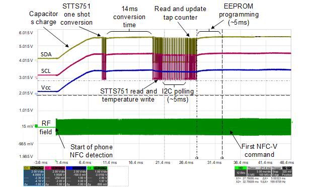
AN5439                                                                                                                List of tables

List of tables

Table 1.   Possible cases of communication arbitration . . . . . . . . . . . . . . . . . . . . . . . . . . . . . . . . . . . . 7
Table 2.   Tag's memory content . . . . . . . . . . . . . . . . . . . . . . . . . . . . . . . . . . . . . . . . . . . . . . . . . . . . 14
Table 3.   Document revision history . . . . . . . . . . . . . . . . . . . . . . . . . . . . . . . . . . . . . . . . . . . . . . . . . 26

                                                        AN5439 Rev 2                                                                3/27
                                                                                                                                             3
List of figures                                                                                                                      AN5439

List of figures

Figure 1.    Application board . . . . . . . . . . . . . . . . . . . . . . . . . . . . . . . . . . . . . . . . . . . . . . . . . . . . . . . . . 5
Figure 2.    Phone 1 tag detection phase . . . . . . . . . . . . . . . . . . . . . . . . . . . . . . . . . . . . . . . . . . . . . . . . 8
Figure 3.    Phone 2 tag detection phase . . . . . . . . . . . . . . . . . . . . . . . . . . . . . . . . . . . . . . . . . . . . . . . . 8
Figure 4.    Phone 3 tag detection phase . . . . . . . . . . . . . . . . . . . . . . . . . . . . . . . . . . . . . . . . . . . . . . . . 9
Figure 5.    RF polling frequency (phone 3) . . . . . . . . . . . . . . . . . . . . . . . . . . . . . . . . . . . . . . . . . . . . . 10
Figure 6.    Phone 2 NDEF read phase. . . . . . . . . . . . . . . . . . . . . . . . . . . . . . . . . . . . . . . . . . . . . . . . . 11
Figure 7.    Phone 1 NDEF read phase. . . . . . . . . . . . . . . . . . . . . . . . . . . . . . . . . . . . . . . . . . . . . . . . . 11
Figure 8.    Battery-less application example hardware setup . . . . . . . . . . . . . . . . . . . . . . . . . . . . . . . 14
Figure 9.    Battery-less NDEF update capture with phone 1 . . . . . . . . . . . . . . . . . . . . . . . . . . . . . . . . 16
Figure 10.   Battery-less NDEF update capture with phone 4 . . . . . . . . . . . . . . . . . . . . . . . . . . . . . . . . 17
Figure 11.   Battery-less NDEF update example result on smartphone. . . . . . . . . . . . . . . . . . . . . . . . . 18
Figure 12.   Battery powered NDEF update chronogram 1/2. . . . . . . . . . . . . . . . . . . . . . . . . . . . . . . . . 19
Figure 13.   Battery powered NDEF update chronogram 2/2. . . . . . . . . . . . . . . . . . . . . . . . . . . . . . . . . 20
Figure 14.   Battery powered NDEF update capture with phone 4 (NDEF update phase). . . . . . . . . . . 23
Figure 15.   Battery powered NDEF update capture with phone 4 (NDEF reading phase) . . . . . . . . . . 23
Figure 16.   Battery powered NDEF update example result on smartphone . . . . . . . . . . . . . . . . . . . . . 24

4/27                                                        AN5439 Rev 2
AN5439                                                                                     Overview

1        Overview

         The EEPROM memory content of the ST25DV-I2C is accessed by either an external
         smartphone or an NFC Forum reader through its RF interface, and by a microcontroller
         through its wired I2C interface.
         The NDEF (NFC data exchange format) message is stored in the EEPROM user memory of
         the ST25DV-I2C.
         When the smartphone is close enough to the ST25DV-I2C antenna, it detects the tag
         presence and starts reading the NDEF message stored in the ST25DV-I2C memory.
         The content of NDEF message is usually static, but the microcontroller updates the content
         of the NDEF message, either in background or dynamically when the phone is approached
         so that the NDEF message always contains dynamic data.

                                         Figure 1. Application board

                                                         NDEF
                                 External events                       Tag detection
                                                                                         Action
                                                                                       triggered
                                 Counters, status...

                                 Sensors values                         NDEF read
               Microcontroller
                                                       ST25DV-I2C

                                 Application board

                                                                                             MSv65106V1

         Various data append dynamically to the NDEF message. For example:
            – Identification information (such as, UID, signature)
            – Tap counter
            – Tamper status
            – MAC (message authentication code)
            – Sensors values (temperature, humidity, pressure, distance, voltage, etc.)
            – GPS position
            – Date and time
            – Battery power level
            – Diagnostic log
         Thanks to the native support of NDEF message by Android and iOS based smartphones, an
         action is automatically triggered on the phone while reading the NDEF message, such as
         opening a browser, sending an email or a text message, or opening an application.

                                           AN5439 Rev 2                                            5/27
                                                                                                          26
Augmented NDEF content update AN5439
2 Augmented NDEF content update
There are three different phases when the NDEF message content is updated by the
microcontroller, these actions are described as follows:
Phase 1 and 2:
1. When the presence of a smartphone is detected, and before the smartphone starts to
read the NDEF message
2. During NDEF read by the smartphone
Phase 3:
3. Any other time, when the smartphone does not try to read the NDEF message
The two first phases listed above are “on-demand update” of the NDEF message. The
content is updated “just in time” each time the smartphone tries to read the NDEF message.
The third one is asynchronous to the smartphone presence. It corresponds to a periodical
update of the NDEF message, or to an update triggered by other external events (such as
an interruption from a sensor).
The following chapters mainly develop the “on demand update” method, since the
asynchronous method does not imply specific techniques.
2.1 Automatic NDEF content update on phone detection
There are several advantages to update NDEF message content on phone detection:
1. Data is always fresh.
2. Application can run battery-less (assuming power consumption of application is low
enough to enable powered through energy harvesting).
However, this is the most challenging method as it requires important timing constraints.
Depending on the amount of data to update it may not be possible to implement this.
In order to understand those timing constraints, one has to first understand how arbitration
between I2C and RF interface works in the ST25DV-I2C and how a smartphone detects the
tag presence and reads the NDEF message.
2.1.1 Arbitration between RF and I2C interfaces in ST25DV-I2C
In the case of NDEF message update on phone detection, the microcontroller, through I2C
interface and the smartphone, through the RF interface, both try to access the ST25DV-I2C.
The microcontroller tries to write the EEPROM memory and the smartphone tries to read the
EEPROM memory.
Due to their nature, these two host controllers are not synchronized, which means that they
both try to access the ST25DV-I2C concurrently. To manage such situation, the ST25DV-
I2C has built-in arbitration circuitry to handle possible concurrent communications from the
RF and I2C sides.
The arbitration is based on the “first talked and first served” principle. It depends on whether
the I²C and RF channels are in the busy state:
– ST25DVI2C is in I²C busy state when decoding and executing an I²C command, and
during the EEPROM programming time that follows a valid I2C write command.
6/27 AN5439 Rev 2AN5439 Augmented NDEF content update
– ST25DV-I2C is in RF busy state when decoding and executing an RF command.
When both interfaces are active, the ST25DV-I2C decodes and executes the first received
command, as detailed in Table 1 which describes possible cases of communication
arbitration.
Table 1. Possible cases of communication arbitration
Initial state event action Event Action
ST25DV-I2C is in the I²C busy RF command transmitted
The RF command is not
state: an I²C command is being during an I²C command
decoded (1)
decoded or executed
ST25DV-I2C is in the RF busy I²C command transmitted The I²C command is not
state: an RF command is being during an RF command decoded (2)
decoded or executed
1. RF commands inventory, stay quiet and addressed RF commands where UID (unique identifier) match
receive no response. Other RF commands receive error code 0Fh.
2. I²C master receives a slave “No Ack” state on 9th bit of first data byte (that is, device select).
The main challenge for updating NDEF message on phone detection is to avoid having the
smartphone sending RF request when I2C is busy (as shown in the first row of Table 1:
Possible cases of communication arbitration). Ultimately, a smartphone receiving an error
on an RF request (or no answer) usually abort the NDEF reading procedure, This must be
avoided.
2.1.2 NDEF detection and reading procedure in smartphones
On smartphones (and all NFC Forum compliant readers) NDEF message reading are
separated in two main phases: tag detection and NDEF read.
Tag detection phase
During the tag detection phase, the smartphone first emits short 13.56 MHz unmodulated
pulses to detect the presence of a 13.56 MHz sensitive object in the field.
If a presence is detected, the smartphone then starts to emit a continuous 13.56 MHz RF
field and start anti-collision procedure for all the NFC Forum technologies supported (this
step is described in the ‘activity” specification of the NFC Forum and is called technology
detection activity).
Most smartphones (Android and iOS) support and poll for NFC Forum NFC-A, NFC-B, NFC-
F and NFC-V technologies. Some smartphones also support and poll for ACM (active
communication mode, in NFC-A or NFC-F or both).
The NFC-V detection and anti-collision is always performed last. This means that there is
some delay between the rising of the RF field and the start of NFC-V anti-collision (inventory
command). This delay is typically around 35 ms but may vary from one smartphone to
another. It can be higher than 35 ms but cannot be less than 30 ms if the four NFC-A/B/F/V
technologies are supported (as defined in NFC Forum specification).
Below Figure 2, Figure 3, and Figure 4 show the tag detection phase of three smartphones
embedding different operating systems captured with an RF spy analyzer. Commands sent
by the smartphone for each NFC technology and RF field status are recorded by the RF spy.
AN5439 Rev 2 7/27
26Augmented NDEF content update AN5439
Figure 2. Phone 1 tag detection phase
NFC-A/B
REQA REQB
NFC-V
Inventory
NFC-F
Polling req
RF Field 34ms
MSv65101V1
The phone 1 detects presence of a tag and then try to detect NFC technologies:
– The phone first sends a very short pulse at 13.56 MHz unmodulated for about 40 μs.
– Then the RF field is off for 5.4 ms.
– After this pause, the NFC technology detection starts: first NFC-A, then NFC-B, NFC-
F and finally, 34 ms after the RF field rising, NFC-V technology.
– The first NFC-V command sent is an inventory command (anti-collision).
Figure 3. Phone 2 tag detection phase
NFC-A/B
REQA REQB
NFC-V
Inventory
NFC-F
Polling req
RF Field 35ms
MSv65102V1
The phone 2 tag detection phase is very similar to the phone 1. Timings are slightly different:
1. First short 13.56 MHz unmodulated pulse duration is about 320 µs.
2. Pause before NFC technology detection is about 5.7 ms.
3. NFC-V anti-collision starts 35 ms after the RF field rising.
8/27 AN5439 Rev 2AN5439 Augmented NDEF content update
Figure 4. Phone 3 tag detection phase
NFC-A/B
ATR_REQ WUPA WUPB
NFC-V
Inventory
NFC-F
ATR_REQ Polling req
RF Field 38ms
MSv65118V1
MSv65103V1
The phone 3 tag detection phase is starting with two pulse of modulated 13.56 MHz RF
field, each followed by a pause, to detect NFC peer-to-peer devices (ACM). After this,
procedure is identical to phone 1 and phone 2. Timings are:
1. 13.56 MHz pulse: 9.5 ms, then 1.8 ms pause
2. 13.56 MHz pulse: 7.8 ms, then 2.78 ms pause
3. NFC tag detection with NFC-V anti-collision 38 ms after the RF field rising.
These three smartphones represent correctly what typically happens with smartphones,
whatever the embedded OS.
This minimum delay of 30 ms before start of NFC-V anti-collision allows the microcontroller
to update the NDEF message content in the ST25DV-I2C memory. ST25DV-I2C can
provide power to boot the microcontroller through energy harvesting as soon has RF field is
rising, and the microcontroller then has 30 ms before the first NFC-V commands (inventory)
to update the NDEF message through I2C. This method is detailed in Section 2.1.4: Battery-
less automatic NDEF content update implementation.
After NFC-V anti-collision phase, if no tag has been found (no answer to the inventory
command), the smartphone stops emitting the RF field to save battery. The inventory
command duration is 2.2 ms.
Then, the smartphone starts a new polling phase later, with a polling frequency usually
around 500 ms as shown in Figure 5.
AN5439 Rev 2 9/27
26Augmented NDEF content update AN5439
Figure 5. RF polling frequency (phone 3)
In case the required time to update the NDEF message is exceeding 30 ms, the
microcontroller allows the use of the polling phase by updating the NDEF message content
on detection of a first polling phase and let the tag answer to the smartphone only on a later
polling phase. The GPO_FIELD_CHANGE interruption of ST25DV-I2C detects the RF field.
The time allowed to update the NDEF message is then only limited by the response time
perceived by the user. However, as the RF field is not present between each polling phase,
it is not possible to use energy harvesting to power the microcontroller, therefore battery or
permanent power is required. This method is detailed in Section 2.1.5: Battery powered
automatic NDEF content update implementation.
NDEF read phase
After NFC-V anti-collision is performed, the smartphone starts the NDEF read procedure.
This procedure is specified by NFC Forum for type 5 tags.
The procedure starts quickly after the inventory command with the read of the CC file: the
phone sends a read single block command to read the first 4 (or 8 bytes) of the tag. Then
the phone sends several read single block commands or read multiple block commands to
read the NDEF message itself (starting quickly after CC file).
Android smartphones add some ISO15693 commands between the inventory of the tag
detection procedure and the NDEF read procedure: get system information and get multiple
block security status.
In NFC Forum NFC-V technology, the minimum timing between two consecutive RF
commands (time between end of the response and start of a new request) is 309 us. In
practice, delay between two RF commands in smartphones is larger, and a typical value
observed is between 1.5 ms to 5 ms. This delay is usually too short to allow any I2C write
access to the ST25DV-I2C EEPROM memory. Updating the NDEF message content during
NDEF read by the smartphone is not a valid option. In fact, any I2C request not terminated
before start of a new RF command can cause an RF error answer and immediate stop of
the NDEF reading process by the smartphone.
10/27 AN5439 Rev 2AN5439 Augmented NDEF content update
Figure 6. Phone 2 NDEF read phase
Block Security
Get Sys Info
Read Single
Read Single
Read Single
Read Single
Read Single
Read Single
Get Multiple
Inventory
NFC-V
Block 0
Block 1
Block 2
Block 3
Block 4
Block 1
Status
RF Field
2.3ms 5.7ms
MSv65105V1
Figure 7. Phone 1 NDEF read phase
Read Single
Read Single
Read Single
Read Single
Read Single
Read Single
Read Single
NFC-V
Inventory
Inventory
Block 1
Block 0
Block 1
Block 2
Block 3
Block 4
Block 0
RF Field
1.6ms 15ms
MSv65107V1
The phone 1 stops emitting the RF field after end of NDEF read, and then regularly re-
activate the RF and sends an inventory command to check that the tag is still present.
2.1.3 Timing constraints for automatic NDEF content update
The constraint is to avoid any RF command fails in order to avoid abortion from the
smartphone. This means no RF command received during execution of an I2C command
(including EEPROM programming time).
In order to update the NDEF message, the microcontroller has to write data into ST25DV-
I2C EEPROM. The ST25DV-I2C programming time is 5 ms per block of 4 bytes (assuming
all bytes belonging to a same row, aka page).
As described in Section : NDEF read phase, the delay between two consecutive RF
commands during the NDEF read phase is less than 5 ms, it is therefore not possible to
write data from I2C in ST25DV-I2C EEPROM during this phase without causing arbitration
conflict with RF commands.
Therefore, to avoid any collision between RF and I2C, the NDEF update must be completed
by the microcontroller between RF field rise and start of anti-collision (first inventory
command), which is usually at least 30 ms for most smartphones.
AN5439 Rev 2 11/27
26Augmented NDEF content update AN5439
NDEF update timing is separated into three phases:
1. Microcontroller wake-up or boot
2. Eventually microcontroller read of data into ST25DV-I2C (typically a counter value) or
into external devices (typically sensors)
3. Microcontroller write into ST25DV-I2C EEPROM memory (NDEF content update)
The microcontroller wakeup and boot phase is not detailed in this application note as it
differs from one microcontroller to another.
The data read phase speed essentially depends on I2C bus frequency and if external
devices required being accessed (that is, sensors with long conversion time).
The ST25DV-I2C memory update speed is mainly dependent on EEPROM programming
time. Let's calculate the duration of an I2C write. We can decompose the I2C write
command in two parts: the I2C bytes transmitted on the bus and the EEPROM programing
phase that starts right after the STOP condition:
– I2C write command duration = (3 + number of bytes to write) / (9 * I2C clock period)
– EEPROM programing duration = 5E-3 * (number of pages to program)
– Total duration of the I2C write = I2C write command duration + EEPROM programing
duration
EEPROM pages are 4 bytes long. Data located on the same page all share the same most
significant memory address bits b16-b2. Programing 1 byte is equivalent to programing 1
page in term of duration. Programing 5 bytes is equivalent to programing 2 pages in term of
duration.
For example, with an I2C clock of 400 KHz, we can write 16 bytes starting at address 000Ch
in 20 ms. If we start at address 000Bh, or if we write 17 bytes starting at address 000Ch, it
takes 25 ms.
Therefore, in 30 ms, the possible amount of data that is updated in the NDEF message is
limited and special care must be taken on the start address and the resulting number of
pages to program.
2.1.4 Battery-less automatic NDEF content update implementation
As described in previous chapters, it is possible to make a battery-less application using a
ST25DV-I2C dynamic tag and a microcontroller to create an augmented NDEF application.
The application must update the NDEF message has soon as the smartphone starts to
provide RF field, and in less than 30 ms to allow correct reading of the NDEF message by
the smartphone.
In principle, this augmented NDEF application does:
– Behave as a standard NFC tag
– Boot the microcontroller when RF field is rising
– Make use of energy harvesting to power the microcontroller and possibly other on-
board external devices
– Read data in ST25DV-I2C and possibly other on-board external devices
– Write data into the ST25DV-I2C memory to update NDEF message content
– Do all this before the first NFC-V command (in less than 30 ms)
12/27 AN5439 Rev 2AN5439 Augmented NDEF content update
In order to achieve this, the prerequisites are:
1. The initial NDEF message has previously been programed into ST25DV-I2C memory.
2. The ST25DV-I2C has been configured with EH enabled at boot (EH_MODE
configuration register=00h).
3. Minimal number of components and components with low power consumption are
used.
To reach the 30 ms max timing, all phases shall be time optimized: capacitor charging when
EH start providing current, MCU boot time, data reading and data writing. Special attention
is required to avoid tearing issues.
During a write of data into EEPROM, it is possible that the RF field gets lost (that is, if
smartphone is removed). To avoid data corruption in that case, an anti-tearing mechanism
must be put in place.
A simple solution is to finish the NDEF update by writing a counter, and to protect only this
counter from tearing. The validity of NDEF data is guaranteed if the counter value is higher
than previous value (counter incremented).
In order to protect the counter from tearing, the energy stored in capacitors is used. As
explained in Section 2.1.3: Timing constraints for automatic NDEF content update, the
EEPROM programming starts only after the stop condition of an I2C write command. During
the EEPROM programming, only the ST25DV-I2C requires being powered through its Vcc
pin, since the microcontroller does not require anymore to provide I2C clock or any other
signal. By only keeping the ST25DV-I2C powered after the stop condition of the last I2C
write (counter update), the power consumption is minimal and the ST25DV-I2C is powered
by capacitor discharge if RF field is removed. This provides an anti-tearing for the counter
update.
Capacitor discharge at constant current is calculated as C=I*dt/dV. Assuming I=350uA (max
value at 3.3V 125°C), dV=3V-1.8V (3V is typical EH output value and 1.8V is the minimal
operating voltage for ST25DV-I2C), and dt=5 ms (typical page write time), the minimum C
value needed to power the ST25DV-I2C to write a page is 1.46uF. If counter is more than 4
bytes, dt must be augmented by steps of 5 ms per page.
The capacitor value must be balanced with capacitor charging time in order not to have a
too long charging time to reach the 1.8V when EH power is starting power delivery. The
capacitor charging time must be taken into consideration when trying to keep the total NDEF
update timing under 30 ms.
Example of battery-less automatic NDEF content update implementation
In this example, the augmented NDEF tag provides a NDEF message containing a URL.
The end of the URL is automatically completed with a temperature value read in a sensor
and a tap counter incremented at each NDEF read.
Hardware setup:
– ST25DV04K dynamic tag, with NDEF message preloaded and EH enabled at boot
– STM8L152 ultra low power MCU
– STTS751 low power, fast conversion time, temperature sensor
– 2 x 4.7uF capacitor (plus 10nF and 100nF capacitors for device decoupling)
AN5439 Rev 2 13/27
26Augmented NDEF content update AN5439
Figure 8. Battery-less application example hardware setup
VEH
Vcc Vcc
4.7uF
ST25DV04K
STM8L152
I2C
Vcc
STTS751
MSv65108V1
The NDEF message is a URL type (example.com/temp=0000/tapcounter=0000) containing
the following data:
– Temperature value and tap counter value addresses are aligned with EEPROM
pages and are only 4 bytes long, to improve programming speed (5 ms for each).
– Temperature and tap counter are written in ASCII format in the NDEF message.
– Tap counter on 4 characters is enough as it provides 10000 values if only decimal is
used, 65536 values if hexadecimal is used and 1.6E6 values if all alphanumeric
values are used.
.
Table 2. Tag's memory content
Block address Block value ASCII Comment
0000 E1 40 40 00 á@@. CCFile
0004 03 2A D1 01 .*Ñ. NDEF TLV
0008 26 55 01 65 &U.e URL value
000C 78 61 6D 70 xamp -
0010 6C 65 2E 63 le.c -
0014 6F 6D 2F 74 om/t -
0018 65 6D 70 3D emp= -
001C 30 30 30 30 0000 temperature value
0020 2F 74 61 70 /tap -
0024 63 6F 75 6E coun -
0028 74 65 72 3D ter= -
002C 30 30 30 30 0000 tap counter value
0030 FE 00 00 00 Þ… TLV Terminator
14/27 AN5439 Rev 2AN5439 Augmented NDEF content update
Sample code executed by the microcontroller:
/* initialize I2C bus and clocks */
I2C_Init();
/* Read I2C sensor to get current temperature */
GetOneTemperature (&data_sensor);
/* update temperature value in NDEF message */
ConvertTempToAscii(data_sensor, &data_char);
I2C_WriteOnePage(ST25DV_ADDRESS_USER, temperature_addr, data_char);
/* poll for end of EEPROM programming (~5ms) */
while( I2C_Poll(ST25DV_ADDRESS_USER) );
/* read current tap counter in tag's EEPROM */
I2C_ReadBuffer(ST25DV _ADDRESS_USER, tapcounter_addr, 4, data_char);
/* increment tap counter and update value in NDEF message */
IncrementTapCounterAscii(&data_char);
I2C_WriteOnePage(ST25DV_ADDRESS_USER, tapcounter_addr, data_char);
/* immediately stop MCU to reduce power consumption */
halt();
The initialization phase is kept minimal to shorten boot time. After finishing I2C write (tap
counter), the microcontroller is set in halt mode to reduce power consumption to minimum
(STTS751 is already in minimal power mode) so that all energy stored in capacitors is
available to ST25DV-I2C in case of RF field off (anti-tearing of tap counter update).
Below Figure 8 and Figure 9 with oscilloscope screenshots show the NDEF update in action
on phone 1 and phone 4.
AN5439 Rev 2 15/27
26Augmented NDEF content update AN5439
Figure 9. Battery-less NDEF update capture with phone 1
16/27 AN5439 Rev 2AN5439 Augmented NDEF content update
Figure 10. Battery-less NDEF update capture with phone 4
With the phone 4, RF field goes off for ~6 ms after first ACM detection, but the 2 x 4.7 uF
capacitors are enough to maintain Vcc voltage above 1.8V.
After presenting the smartphone on the tag's antenna, the smartphone automatically opens
the web browser, with the URL containing dynamic information about temperature (+ 26C)
and tap count (2Ah, 42 taps) as shown in Figure 11.
AN5439 Rev 2 17/27
26Augmented NDEF content update AN5439
Figure 11. Battery-less NDEF update example result on smartphone
2.1.5 Battery powered automatic NDEF content update implementation
When timing constraint of 30 ms is not achievable, another method allowing longer time to
update the NDEF message is possible.
As seen in Section 2.1.2: NDEF detection and reading procedure in smartphones,
smartphones are continuously polling for tags presence by sending short RF field bursts.
This method makes use of capacity of ST25DV-I2C to detect those RF field bursts to trigger
the NDEF update. Once NDEF is updated, the ST25DV-I2C is configured to answer
normally to the next smartphone polling sequence, until the NDEF message is read. This
create a small delay in answer when a smartphone taps the tag, but it is limited to 500 ms or
less with most smartphones.
Since there is no RF field between two polling sequences, energy harvesting cannot be
used with this method the ST25DV-I2C and the microcontroller must be externally powered.
In principle, this augmented NDEF application does:
– Behave as a standard NFC tag
– Wake-up the microcontroller on RF events
– Use a battery or permanent supply to power the microcontroller and other possible on
board external devices
– On first RF field rising, update NDEF message. The battery power allows NDEF
update even when RF field is off
– On next RF field rising, wait for NDEF read from the smartphone.
– After detection of NDEF read by the smartphone, wait for the next RF field rising to
update the NDEF again
– The initial NDEF message is first programmed into ST25DV-I2C memory
This augmented NDEF method is based on RF events detection. The application must
detect a RF field rising event, and an NDEF message read.
The RF field rising detection is performed using the ST25DV-I2C RF_FIELD_RISING event
detection.
18/27 AN5439 Rev 2AN5439 Augmented NDEF content update
The NDEF message read can be interpreted by combining two event detections:
RF_ACTIVITY and RF_FIELD_FALLING. The smartphone finish reading the NDEF
message if RF activity has been detected and the RF field goes off (meaning the
smartphone has been removed).
A global variable is used as a flag to keep trace if NDEF update has already been done or
not:
– Upon detection of RF field rising, the microcontroller checks this variable to know if
NDEF update must be done or not. If flag is not set, NDEF update is done and the
flag is set.
– Upon detection of RF activity and RF field falling, the microcontroller checks this flag
to know if NDEF update has previously been achieved. If yes, NDEF message is
considered read and the flag is unset.
During NDEF update, the ST25DV-I2C is set in RF_SLEEP mode so that any incoming RF
command is just ignored. This provides two benefits:
– Prevent any false or partial detection of the tag by the smartphone during the NDEF
update
– Prevent any RF perturbation during I2C access (I2C accesses are not blocked by any
RF access)
With this method, it is not required to implement any anti-tearing technique such as, for the
battery-less method, since there is not risk of tearing as the ST25DV-I2C is continuously
powered by the battery during EEPROM programming.
The following chronograms; Figure 12 and Figure 13 summarize the complete NDEF
update sequence:
Figure 12. Battery powered NDEF update chronogram 1/2
Next smartphone’s
First smartphone’s tag Inventory tag detection
detection sequence Inventory followed by NDEF read
Not answered sequence
NFC-V
RF Field
GPO
I2C
NDEF message update
ST25DV-I2C in RF_SLEEP state
GPO FIELD_RISING and NDEF GPO FIELD_RISING and NDEF
not updated = update triggered already updated = no update
MSv65112V1
AN5439 Rev 2 19/27
26Augmented NDEF content update AN5439
Figure 13. Battery powered NDEF update chronogram 2/2
Next smartphone’s tag Next smartphone’s tag Inventory
detection sequence Inventory followed by NDEF read detection sequence Not answered
NFC-V
RF Field
GPO
I2C
NDEF message update
ST25DV-I2C in RF_SLEEP state
GPO FIELD_RISING and NDEF GPO FIELD_FAILLING and GPO FIELD_RISING and NDEF not
already updated = no update RF_ACTIVITY = end of NDEF read updated = update triggered
MSv65113V1
Example of battery powered automatic NDEF content update implementation
In this Example of battery powered automatic NDEF content update implementation, the
augmented NDEF tag provides an NDEF message that contains an SMS. The message is
automatically updated with the tag UID, three sensors’ values and a tap counter
incremented at each NDEF read.
Hardware setup:
– A X-NUCLEO-NFC05A1 shield, embedding a ST25DV04K dynamic tag, with NDEF
message preloaded
– A NUCLEO-L053R8 board, embedding a STM32L053 microcontroller
ST25DV-I2C memory is preloaded with the NDEF message, with sensors and tap counter
values set to 0.
Sample of code executed by the microcontroller:
/* Init ST25DV driver */
while( NFC04A1_NFCTAG_Init(NFC04A1_NFCTAG_INSTANCE) != NFCTAG_OK );
/* Set EXTI settings for GPO Interrupt */
NFC04A1_GPO_Init();
/* Set GPO Configuration: RF Field change and RF activity */
NFC04A1_NFCTAG_ConfigIT(NFC04A1_NFCTAG_INSTANCE,ST25DV_GPO_ENABLE_MASK |
ST25DV_GPO_FIELDCHANGE_MASK | ST25DV_GPO_RFACTIVITY_MASK);
/* main loop */
while(1)
{
if( GPOActivated == 1 )
{
/* Read ITSTS_Dyn to determine source of the GPO interrupt */
NFC04A1_NFCTAG_ReadITSTStatus_Dyn(NFC04A1_NFCTAG_INSTANCE, &ItStatus )
;
switch( ItStatus )
{
case ST25DV_ITSTS_DYN_FIELDRISING_MASK:
case ST25DV_ITSTS_DYN_FIELDRISING_MASK |
ST25DV_ITSTS_DYN_FIELDFALLING_MASK:
20/27 AN5439 Rev 2AN5439 Augmented NDEF content update
case ST25DV_ITSTS_DYN_FIELDRISING_MASK |
ST25DV_ITSTS_DYN_RFACTIVITY_MASK:
/* RF field rising detected */
if( NDEF_update_done == 0) /* update to be done ? */
{
/* set ST25DV in RF_SLEEP mode */
passwd.MsbPasswd = 0; passwd.LsbPasswd = 0;
NFC04A1_NFCTAG_PresentI2CPassword(NFC04A1_NFCTAG_INSTANCE, passwd
);
NFC04A1_NFCTAG_SetRFSleep( NFC04A1_NFCTAG_INSTANCE );
/* update NDEF content */
MX_NFC4_NDEFUpdate();
NDEF_update_done = 1;
/* exit ST25DV from RF_SLEEP mode */
NFC04A1_NFCTAG_ResetRFSleep( NFC04A1_NFCTAG_INSTANCE );
passwd.MsbPasswd = 123; passwd.LsbPasswd = 456;
NFC04A1_NFCTAG_PresentI2CPassword(NFC04A1_NFCTAG_INSTANCE, passwd
);
}
break;
case ST25DV_ITSTS_DYN_FIELDFALLING_MASK |
ST25DV_ITSTS_DYN_RFACTIVITY_MASK:
case ST25DV_ITSTS_DYN_FIELDRISING_MASK |
ST25DV_ITSTS_DYN_FIELDFALLING_MASK | ST25DV_ITSTS_DYN_RFACTIVITY_MASK:
/* RF activity and RF field falling detected */
if( NDEF_update_done == 1) /* update already done ? */
{
/* NDEF has been read, next RF field rising: update to be done */
NDEF_update_done = 0;
}
break;
case ST25DV_ITSTS_DYN_RFACTIVITY_MASK:
case ST25DV_ITSTS_DYN_FIELDFALLING_MASK:
default:
break;
}
GPOActivated = 0;
}
}
/* call back function from IT */
void BSP_GPO_Callback(void)
{
GPOActivated = 1;
}
AN5439 Rev 2 21/27
26Augmented NDEF content update AN5439
The STM32L0 Series is configured so that the GPO interruption is setting the GPOActivated
global variable to 1. The main loop is polling on this variable value change to start the NDEF
update process. The first step is to read the ITSTS_Dyn status register to check the nature
of the RF event. Then, depending on the RF event and on the value of NDEF_update_done
global variable, decision is made to update or not the NDEF message.
Below in Figure 14 and Figure 15 logic analyzer screenshots show the NDEF update in
action on phone 4.
22/27 AN5439 Rev 2Figure 14. Battery powered NDEF update capture with phone 4 (NDEF update phase)
AN5439
RF Field
Smartphone’s tag detection and anti-collision
RF frames
RF Field rising detection Inventory
NDEF update (not answered)
GPO
I2C
AN5439 Rev 2
MSv65114V1
Figure 15. Battery powered NDEF update capture with phone 4 (NDEF reading phase)
RF Field
Augmented NDEF content update
Next smartphone’s tag detection and anti-collision Smartphone NDEF reading
RF frames
RF activity detection Inventory
RF Field rising detection (answered)
GPO
Check on GPO interrupt source
I2C
23/27
MSv65115V1Augmented NDEF content update AN5439
After presenting the smartphone on the tag's antenna, the smartphone automatically opens
the messaging application, with the SMS containing tag's UID, up-to-date sensors value and
the tap count as shown in Figure 16.
Figure 16. Battery powered NDEF update example result on smartphone
2.2 Periodical NDEF content update and update based on
external events
If NDEF update cannot be done dynamically and synchronously to the smartphone
presence detection, it can then be done asynchronously.
In this case, the NDEF message content is update periodically, or on other external events,
independently of any RF activity. This is the case for example if you want to update NDEF
content each time an alarm is triggered in the application, or in case the NDEF message is
used as a data log.
As I2C and RF accesses are asynchronous in this method, the microcontroller and the
smartphone try to access the ST25DV-I2C at the same time, which is not recommended. To
avoid any possible conflict between I2C and RF, it is recommended to set the ST25DV-I2C
in RF_SLEEP mode during update of the NDEF message content.
However, such method does not require any specific techniques, and therefore no
information is developed in this application note.
24/27 AN5439 Rev 2AN5439 Augmented NDEF content update
2.3 Configuration data considerations
A good practice is to store application configuration data into the NFC EEPROM instead of
the microcontroller Flash memory.
The advantage of storing settings (such as, sensors enabled, sampling period) in the NFC
EEPROM instead of the microcontroller Flash memory is that an NFC reader can directly
read and write the application settings (even if the application is not powered).
In case of augmented NDEF, all the dynamic NDEF parameters are stored into the ST25DV-
I2C memory (such as, information and addresses to update inside the NDEF message).
The reader can then update the NDEF message body and the addresses of bytes always
updated dynamically at the same time. The microcontroller reads those configuration bytes
before updating the NDEF message.
This is performed by defining two areas in ST25DV-I2C user memory, with area 0 always
containing the CCFile and the NDEF message, and area 1 containing the configuration
data. Both areas can be protected independently with different passwords if required.
AN5439 Rev 2 25/27
26Revision history AN5439
3 Revision history
Table 3. Document revision history
Date Revision Changes
10-Apr-2020 1 Initial release.
Updated Section 2.1: Automatic NDEF content update
28-Apr-2020 2
on phone detection.
26/27 AN5439 Rev 2AN5439
IMPORTANT NOTICE – PLEASE READ CAREFULLY
STMicroelectronics NV and its subsidiaries (“ST”) reserve the right to make changes, corrections, enhancements, modifications, and
improvements to ST products and/or to this document at any time without notice. Purchasers should obtain the latest relevant information on
ST products before placing orders. ST products are sold pursuant to ST’s terms and conditions of sale in place at the time of order
acknowledgement.
Purchasers are solely responsible for the choice, selection, and use of ST products and ST assumes no liability for application assistance or
the design of Purchasers’ products.
No license, express or implied, to any intellectual property right is granted by ST herein.
Resale of ST products with provisions different from the information set forth herein shall void any warranty granted by ST for such product.
ST and the ST logo are trademarks of ST. For additional information about ST trademarks, please refer to www.st.com/trademarks. All other
product or service names are the property of their respective owners.
Information in this document supersedes and replaces information previously supplied in any prior versions of this document.
© 2020 STMicroelectronics – All rights reserved
AN5439 Rev 2 27/27
27You can also read