Industrial Internet of Things Based Programmable Logic Controller
←
→
Page content transcription
If your browser does not render page correctly, please read the page content below
International Journal of Innovative Technology and Exploring Engineering (IJITEE)
ISSN: 2278-3075, Volume-8 Issue-7, May, 2019
Industrial Internet of Things Based
Programmable Logic Controller
G. Joselin Retna Kumar, Sheikh Mohammed Afzal, A. John Pravin
communication for PLC. They give us some brief advantages
Abstract: The proposed design of a customized PLC of using wireless system over wired in industries. Later, they
includes a compact setup which is an integral part of industrial go on to give a
automation and to control various batch processes. The design
takes into account, a wireless communication channel between hardware description of the system and its specifications.
the PLC and the supervisory server system, which is achieved by Reference [4] In the Distributed Control System (DCS), the
embedding a wireless module into the PLC setup. The designed
data exchange between the Programmable Logic Controllers
setup also eliminates the hassle of long, multi-loop wiring which
(PLC) is usually completed through the wired network.
can be inconvenient to troubleshoot specific problem and to take
corrective action instantly. By utilizing the wireless ZigBee wireless communication technology is introduced in
communication achieved by integrating an ESP8266 module. It the design of a new type of PLC to overcome the
is easier to connect with the process in a much simpler manner. communication cable boundaries. In [5] the planning is
The most important feature is that data that is transmitted can be concentrated on development of mobile automatic guided
uploaded into a Cloud Storage, with a secure server connection. vehicle (AGV) controlled by decentralized edge PLC
The process data from the PLC is uploaded onto the server and SIMATIC ET200S hardware. Wireless communications area
can be monitored by the personnel supervising the plant unit considered because the two leading two-way
operation. The data which is accessed over the server includes communications technologies for the rising good Grid
the field monitoring points relevant to the particular process. applications in [6], because the received signals from the
Conclusions: Wireless communication between the supervisory NB-PLC and wireless links area unit allowed to hold
server system and the PLC is possible and the field monitoring
identical info, to supply robustness against the interference
points can be monitored via the Cloud Server.
encountered on each links. In [7] the system is focused on
Index Terms: Automation, Programmable Logic Controller, developing an ESP8266 based Low cost Wi-Fi based wireless
SCADA, Wireless Technology. sensor network, the IEEE 802.11n protocol is used for
system. In most of the existing wireless sensor network are
NOMENCLATURE designed based on ZigBee and RF frequencies. Reference [8]
PLC Programmable Logic Controller discusses the natural bottleneck between mass sensor
RAM Random Access Memory information and Electric Power Communication
PID Proportional Integral Derivative Transmission Network to put forward the concept of
ADC Analog to Digital Converter information aggregation layer under the background of
MCU Micro Controller Unit heterogeneous network convergence. And lastly, the [9]
deals with the sample IOT based security system which
I. INTRODUCTION utilizes the ESP8266 as the wireless module in order to
implement the wireless technology. Delta PLC of the model
The asphalt mixing is discussed in [1] vital for pavement DVP14-SS2 is used for the customization. They are a
construction. They usage of PLC to control the NP3000CA second-generation model which consists of 8 Digital Inputs
asphalt mixing equipment. Further along the paper they give and 6 Digital Outputs of a very slender make. High speed
details about the control process and various parameters timers and counters can be accessed for multiple timing and
involved in it. Ladder logic of PLC is also discussed which scheduling of processes. It also sports an adjustable serial
sheds light on the way in which the equipment is controlled. port and an expansion bus which facilitates additional
Also, the use of PLC SIMATIC ET200S CPU to control an modules for increased supervision without extra wiring and
automated guided vehicle in [2], involves detailed is powered by the SMPS connections. An RS232 cable is used
description of the AGV, its architecture and uses. The to connect to the MAX3232 converter, from which the Wi-Fi
authors also go into detail about various components module ESP8266 is connected, with the software program
involved in it and about various problems and solutions they downloaded onto it from the Arduino in order to establish
adapted to overcome these problems. Li, Munigala and Zeng wireless transmission and reception. The MAX3232 is used
have utilized Zigbee technology in [3] to implement wireless to converts the signals from the RS232 serial port to the
proper signal which are used in the TTL compatible digital
Revised Manuscript Received on May 10 ,2019. logic circuits. The MAX232 converts the signals like RX,
Dr. G. Joselin Retna Kumar, Electronics and Instrumentation TX, CTS, and RTS and it is a dual driver/receiver.
Engineering, SRM Institute of Science and Technology, Chennai, India.
Sheikh Mohammed Afzal, Electronics and Instrumentation Engineering,
SRM Institute of Science and Technology, Chennai, India.
A. John Pravin, Electronics and Instrumentation Engineering, Chennai,
India.
Published By:
Blue Eyes Intelligence Engineering
Retrieval Number: G6310058719 /19©BEIESP 1636 & Sciences Publication
Industrial Internet of Things Based Programmable Logic Controller

 Data from the ESP8266 is pushed to the Cloud Server              NPN and PNP type. BJT and MOSFET are some widely
(Firebase) for monitoring of the process variables relevant to    available transistors in the market. A transistor output is
the particular Plant. Plant processes can be automatically        small and fast in operation. It also has a long lifetime.
fine-tuned with the help of PID loops as they are supported by      TRIAC outputs are used only for AC applications. Similar
this device. Pulse generation at great speeds are done for        to transistor output, its output is faster and has a long
various types of motor motions and their control                  lifetime. They are the solid-state choice for AC currents and
applications. The software for programming this module is         requires additional components called snubbers. Back
complimentary and can be downloaded for the required OS           current is produced when inductive loads are turned on. This
without any trouble.                                              resembles a voltage increase going through the system. This
                                                                  is hazardous to output relays. Hence snubber circuit is used to
              II. SYSTEM DESCRIPTION                              provide protection to PLC outputs to prevent damages.
  The proposed system is to be designed using a DELTA PLC
                                                                  A. PLC Power Supply
of the model DVP14-SS2, wherein the inputs to the PLC
would be given through the INPUT MODULE, which are                 PLC is given 24V DC which comes from an SMPS. A
field connected to measure the various process variables. The     switched mode power supply (SMPS) converts AC or DC
OUPUT MODULE is connected to the microcontroller in               power to respective DC power by utilizing switching devices.
order to verify whether the setpoints are satisfied or not.       At peak frequencies, these are turned on or off. Devices like
ARDUINO UNO R3 is used as the microcontroller here. The           inductors or capacitors are used to supply power to the
POWER SUPPLY is given through the SMPS, to the PLC.               switching device when it is in a non-conductive state. We get
The Data received from the PLC, connected to the process is       a 24V AC power supply which is given to an SMPS. It
then sent to the ARDUINO UNO R3 which makes sure that             rectifies and regulates the input to produce 24V DC power
the data is within the acceptable limits of allowance, due to     supply. This power is directly given to the PLC.
the setpoint adjustments. As, the setpoints are adjustable, the
wireless communication is established through the ESP8266         B. Arduino Power Supply
which allows the data that is received on the ARDUINO              Arduino requires 5V to operate. This 5V DC is directly
UNO R3 to be transmitted on the cloud server for monitoring       given to the Arduino by a USB cable directly connected to
by the personnel in charge for the plant process.                 any computer or laptop.

                                                                         III. INTERFACING ARDUINO AND PLC
                                                                    Six inputs are received from the PLC by Arduino. This data
                                                                  is stored in the PLC and sent to ESP8266 via Tx and Rx pins.
                                                                  An Arduino has at least one serial port. This is also known as
                                                                  UART or USART. It can communicate via Tx and Rx pins or
                                                                  USB cable. As the Tx and Rx pins of ESP8266 are connected
                                                                  with Rx and Tx pins of Arduino, data is sent effortlessly.
                                                                  Arduino at this end is coded for Rx pin as it receives this data.
                                                                  It then sends it to the process and runs it efficiently. The
                                                                  sensor data is then sent to Arduino which in turn transmits it
                                                                  to ESP8266 which goes to the other ESP8266 wirelessly.
                                                                  Then it is sent to the PLC via the Arduino present there. A
                                                                  relay is placed there for this purpose. The supply for this
                       Fig. 1. Block Diagram.                     Arduino is given through another Switched mode power
                                                                  supply placed here. 24V DC from it is given to a voltage
PLC outputs are of different types. It can be relay, transistor
                                                                  regulator circuit which steps it down to 12V for Arduino
or TRIAC types.
                                                                  usage. ESP8266 requires 3.3V to operate. This voltage is
 Relay output are voltage independent and can be easily
                                                                  given by the Arduino. When Vin is given 3.3V and Ground
interfaced with user’s de-vices. They are mechanical contacts
                                                                  connected properly the ESP8266 becomes operational. Tx
which are non-polarized and can switch between AC and DC
                                                                  and Rx pins of ESP8266 are connected to Rx and Tx pins of
with ease. These outputs are used to control medium loads
                                                                  Arduino respectively. ESP8266 then transmits this data
(up to 2A). It consists of NO (Normally Open) and NC
                                                                  wirelessly via hotspot to another ESP8266. ESP8266 is coded
(Normally Closed) contacts. Normally open switches are
                                                                  to first initialize hotspot communication. The other ESP8266
initially open and wont conduct electricity, once they are
                                                                  is made to connect to this hotspot. When this connection is
pressed, they enable the power initiation as they get
                                                                  initialized ESP8266 directly sends data from Arduino to the
energized. Normally closed switches are the exact opposite as
                                                                  other Arduino wirelessly and receives it back for further
they keep conducting electricity until they get pushed. It can
                                                                  communication.
work with both AC or DC.
 Transistor outputs are only suitable for DC applications.
When a less current is given to the transistor base by the PLC,
the output closes. This enables the device connected to the
PLC to function. There are two types of transistor outputs,

                                                                      Published By:
                                                                      Blue Eyes Intelligence Engineering
Retrieval Number: G6310058719 /19©BEIESP                      1637    & Sciences Publication
International Journal of Innovative Technology and Exploring Engineering (IJITEE)
                                                                            ISSN: 2278-3075, Volume-8 Issue-7, May, 2019

 A call back function is also initialized for receiving back the     The ladder logic is stored in the PLC and the data is passed
data from the other ESP8266 module which makes up the              through the RS-232 cable to the MAX 3232 converter in
bi-directional communication.                                      order to convert the RS232 protocol to TTL logic.
                                                                     The Arduino Software Serial Program is uploaded and then
                      IV. WORKING                                  transmitted to the ESP8266, so in effect the software
                                                                   program is already contained in the Wi-Fi Module.
 The proposed PLC consists of 8 inputs and 6 outputs. Only
                                                                     The ladder logic can be explained as to set up the
3 inputs of the PLC are used to incorporate a switch and
                                                                   communication parameters for the PLC with regards to the
sensor device. All the 6 outputs are used to control 3 motors.
                                                                   RS-232 protocol and its various function codes are as
 Arduino Uno is interfaced with the PLC with its respective
                                                                   follows:
pins. All the 6 output pins are directly given to 6 digital pins
                                                                   Only 8-bit mode is supported. Communication format and
of Arduino. Arduino is coded where each pin is defined and
                                                                   speed are specified by lower 8 bits of D1036. STX/ETX
the device is prepared for transmission. The Arduino is
                                                                   setting function (M1126/M1130/D1124~D1126) is not
interfaced with ESP8266 for wireless transmission.
                                                                   supported. High byte of 16-bit data is not available. Only low
 ESP8266 or NodeMCU is a Wi-Fi module suitable for
                                                                   byte is valid for data communication. Write the data to be
wireless transmission. This module receives data from the
                                                                   transmitted in advance into registers starting from D100 and
Arduino via its Tx and Rx pins. ESP8266 then creates its
                                                                   set M1312 (COM1 sending request) as ON When X0 = ON,
own Wi-Fi hotspot for the other ESP8266 to connect to it.
                                                                   RS instruction executes and PLC is ready for
Data is thus transferred wirelessly. ESP8266 is then coded to
                                                                   communication. D100 will then start to send out 4 data
receive and transmit data of respective pins of the Arduino
                                                                   continuously. When data sending is over, M1312 will be
back and forth without any hiccups.
                                                                   automatically reset. (DO NOT apply RST M1312 in
 We use mesh libraries of ESP8266 to achieve hotspot
                                                                   program). After approximate 1ms, PLC will start to receive 7
communication. This communication is preferred as the data
                                                                   data and store the data in 7 consecutive registers starting
can be sent quickly and received back for simultaneous
                                                                   from D120. When data receiving is completed, M1314 will
wireless transmission. It eliminates any time lag and ensures
                                                                   automatically be ON. When data processing on the received
a smooth running of process. The ESP8266 creates its
                                                                   data is completed, M1314 has to be reset (OFF) and the PLC
hotspot, this means it has its own SSID and pass-word. The
                                                                   will be ready for communication again.
other ESP8266 module is given these credentials and made
to connect to this hotspot.
 The two NodeMCUs are connected to Arduino                                             VI. LADDER LOGIC
microcontroller from either side. The Arduino boards are
capable for of operating at low voltage of 5V which is one of
the advantageous features of the hardware because 5V
voltage can be easily obtained. The first Arduino board
commencing the circuit is further connected to PLC where
the ladder logic of the process to be controlled is fed.

                    V. INTERFACING

                                                                                 Fig. 3. Ladder Logic Implemented in Delta PLC.

                                                                    The Software Program installed on the Arduino facilitates
                                                                   the wireless communication which can be represented as:

                Fig. 2. PLC Interfaced with ESP8266.

 This logic is again connected to the latter NodeMCU and
Arduino board. Due to the IOT server created, the data from
NodeMCU is shared to the Arduino and the process is
controlled at a controlled voltage. This circuit is connected to
the relay for starting and stopping the circuit as and when
required.

                                                                       Published By:
                                                                       Blue Eyes Intelligence Engineering
Retrieval Number: G6310058719 /19©BEIESP                       1638    & Sciences Publication
Industrial Internet of Things Based Programmable Logic Controller
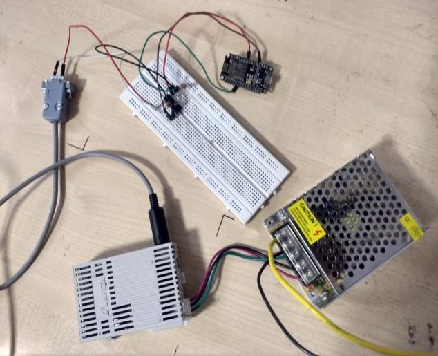
Fig. 4. Software Program Implemented for Communication.
Fig. 6. App Homepage
VII. FLOWCHART AND APP DEVELOPMENT
The Flowchart for the following Software Program can be
given as: VIII. CONCLUSION
In order to make PLC outputs ready for wireless
transmission we needed a micro-controller which can
process this data and send it for further communication.
What better microcontroller than Arduino could fit the bill
and seamlessly interface with the PLC for effortless
transmission of output signals from the PLC.
Wired signals to the PLC have been prevalent for the past
decade or more, which causes increasing problems in
periodic shutdown of the powerplants resulting in the loss of
productivity and revenue. These production and revenues
losses for the industrial plants can be better managed by
integrating a wireless PLC setup which can manage the
losses in a way that even if there is a problem resulting in a
disturbance in the process, there can be a faster recovery of
the systems, where systems can be back online much faster
than wired systems. It can also be said that the wireless
modules are more prone to online spying and theft, which
can lead to loss of vital information relating to the process or
industry or misuse of information by some third-party
organization. It is in this regard that the wireless PLC setup,
when implementing the IOT platform is guarded with unique
user credentials which are provided only to the factory
personnel in charge. A log can be kept in order to identify the
record of the plant process being handled periodically over a
Fig. 5. Flowchart
week. All in all, the wireless PLC provides a cutting-edge
platform for the latest IOT innovations in the field of PLC,
The Application was developed in order to remotely for smarter and more sophisticated method of monitoring
monitor the data being transmitted wirelessly through the and controlling vital industrial process.
PLC, the data shows the various field-monitoring points The future scope would be for integrating some real time
which are gathered in the Power Plant System, where the process into the setup in order to test the effects of the
various setpoints and process variables are noted, in order to setpoint and monitoring the security in a Plant Control
maintain at the optimum levels. System.
Published By:
Blue Eyes Intelligence Engineering
Retrieval Number: G6310058719 /19©BEIESP 1639 & Sciences PublicationInternational Journal of Innovative Technology and Exploring Engineering (IJITEE)
ISSN: 2278-3075, Volume-8 Issue-7, May, 2019
REFERENCES
1. Luo Lianshe, Liu Baoguo, "Research on PLC-based Control System for
mix-ing", IEEE, 2010, 978-1-4244-7161-4/10
2. Kajan, Martin, et al. "Control of Automated Guided Vehicle with PLC
SIMATIC ET200S CPU", American Journal of Mechanical Engineering,
2013, Volume 1, Issue 7
3. Xiaolong Li, Sairam Munigala, Qing-An Zeng, "Design and
Implementation of a Wireless Programmable Logic Controller System",
IEEE 2010, Pg. 3138 - 3141
4. Xinsheng Che, Yun Sun, Bo Li, Hui Xu, "Design and System
Performance Test of a Kind of PLC with Wireless Communication
Function", IEEE 2017, Pg. 762 – 765
5. PNO, PROFINET System Description -Technology and
Application, PROFIBUS Nutzerorganisation e.V. PNO,
Germany, June 2011.
6. Mostafa Sayed and Naofal Al-Dhahir, "Narrowband-PLC/Wireless
Diversity for Smart Grid Communications" IEEE 2014, Pg No. 2966 –
2971.
7. Tejas Thaker, "ESP8266 based Implementation of Wireless Sensor
Network with Linux Based Web-Server", IEEE 2016,
978-1-5090-0669-4/16.
8. D. Han, J. Zhang, Y. Zhang and W. Gu, "Convergence of Sensor
Network-s/Internet of Things and Power Grid Information Network at
Aggregation Layer", IEEE 2010, 978-1-4244-5940-7/10.
9. Ravi Kishore Kodali, Ashwitha Naikoti, "ECDH based Security Model
for IoT using ESP8266", IEEE 2016, Pg 629 – 633.
Dr. G. Joselin Retna Kumar, M.E, Ph.D., Associate
Professor, Email Id: joselin.rk@ktr.srmuniv.ac.in
Area: Process control and Instrumentation, Automation.
Affiliation: Department of Electronics and
1 Instrumentation Engineering, Kattankulathur Campus,
SRM Institute of Science and Technology
Sheikh Mohammed Afzal, B.Tech, Department of
Electronics and Instrumentation Engineering, SRM Institute
of Science and Technology, Chennai, India Email Id:
afzal.sm@hotmail.com
A. John Pravin, B.Tech, Department of Electronics and
Instrumentation Engineering, SRM Institute of Science and
Technology, Chennai, India.
Email Id: johnpravina@gmail.com
to
Published By:
Blue Eyes Intelligence Engineering
Retrieval Number: G6310058719 /19©BEIESP 1640 & Sciences PublicationYou can also read