Owners Handbook - Okto Caravans
←
→
Page content transcription
If your browser does not render page correctly, please read the page content below
Owners Handbook

         1|Page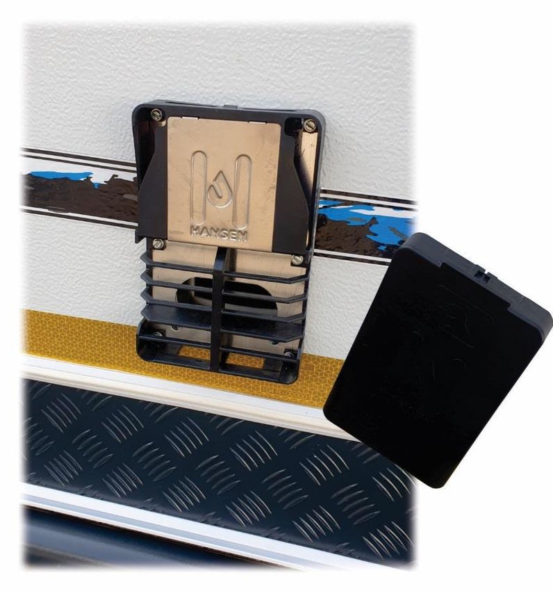
Owners Handbook

                                   INDEX
Terms of warranty….………………………………………………………………………………………………….Page                3
Service records……….………………………………………………………………………………………………….Page                4
Coupling the caravan to you vehicle…………………………………………………………………………..Page        6
Wheels and tyres……………………………………………………………………………………………………….Page                 7
Spare wheel……………………………………………………………………………………………………………….Page                 7-8
Braking system…………………………………………………………………………………………………………..Page              9-11
Electrical system………………………………………………………………………………………………………..Page           11-13
Fuses………………………………………………………………………………………………………………………….Page                    12
Battery……………………………………………………………………………………………………………………….Page                   15
7-Pin plug and road lights…………………………………………………………………………………………..Page          16
Water system – Villa and Cabana……………………………………………………………………………….Page          17
Water system – Gravellors…………………………………………………………………………………………Page          18-19
Hot water system – Gravellors…………………………………………………………………………………..Page       19-21
Windows……………………………………………………………………………………………………………………Page                     22
Specifications…………………………………………………………………………………………………………….Page                23

                                                                        2|Page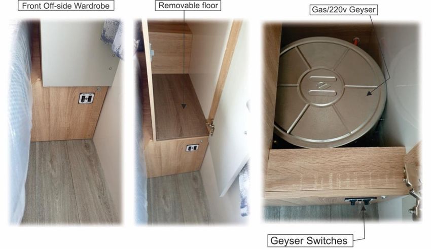
Owners Handbook

Thank you for purchasing an OKTO caravan, we hope you will have many happy holiday moments and
make great memories in your New OKTO.
Please be sure that you read and understand the contents of this handbook as it will guide you to a
better understanding of your new OKTO. This Handbook is provided purely as a guideline and any
instructions or procedures not listed in the handbook can be obtained from your local OKTO dealer.

Terms of warranty
All new OKTO caravans are covered by a one-year warranty. This warranty is transferable. This
warranty becomes valid from the date of purchase but is effective only when the OKTO dealer has
received the signed Owner’s Acceptance Certificate. OKTO Caravans (Pty)Ltd warranty will guarantee
the caravan against failures or defects that may arise from faulty workmanship or materials for a
period of one years from date of purchase.
Misuse of parts or components of the caravan are not covered under this warranty. For the warranty
    repairs the caravan will need to be taken to an approved OKTO dealer at the owner’s expense.

   Special conditions of warranty
   1. Since neither the axle manufacturer nor OKTO (Pty)Ltd have any control over it after leaving
      the factory, wheel bearings and the alignment of the axles do not carry any warranty.

   2. The OKTO warranty does not cover the tyres or fitted appliances. This will need to be
      claimed from the applicable tyre or appliance manufacturer with the assistance of an OKTO
      dealer.

   3. The caravan should not be used for purposes other than holidays. Even though it is possible
      to permanently live in the OKTO caravan, the caravan is not designed as a permanent
      dwelling.

   4. The OKTO range of caravans will need to be serviced by an authorized OKTO dealer at least
      once a year.

   5. The warranty does not cover any caravan that will be used as a rental unit.

   6. The OKTO caravan will need to be returned to and authorized dealer for any warranty
      repairs. This will ensure that the repair is done under the correct supervision and with the
      correct tools and parts.

   7. OKTO is responsible only as described in the warranty and will not be held liable for any loss,
      damage, injury or consequential or resulting liability caused by or due to any defects.

   8. OKTO reserves the right to refuse responsibility for any cost of any repairs that were
      undertaken by a repairer other than an authorised OKTO dealer unless prior authorisation
      was obtained from OKTO (PTY) Ltd or an OKTO approved dealer.

                                                                                          3|Page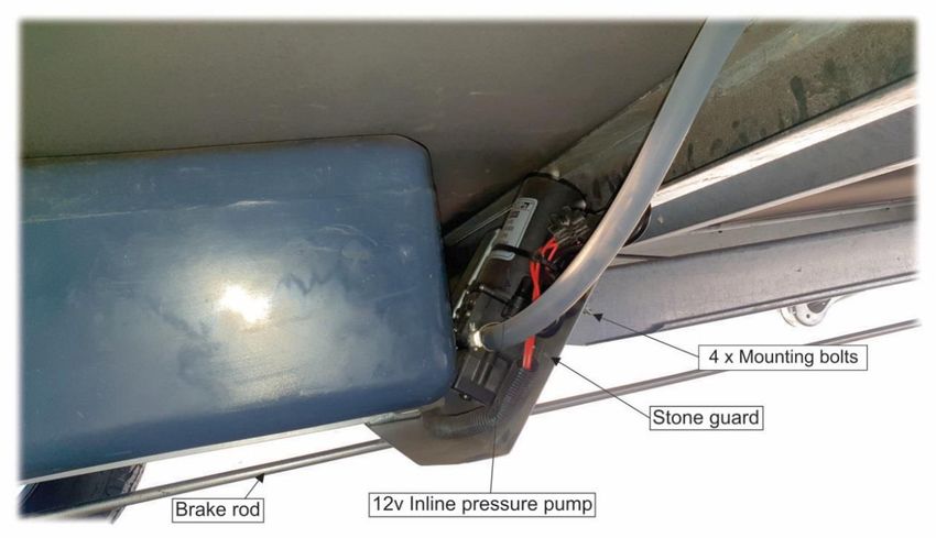
Owners Handbook

9. OKTO has the right to cancel this warranty if any unauthorized alterations or modifications
   are made to the caravan or any parts included.

10. The OKTO warranty excludes all warranties, conditions and liabilities whatsoever, expressed,
    implied or imposed by Common Law, statute, or otherwise.

11. This warranty is valid only in the Republic of South Africa.

12. OKTO (Pty) Ltd reserves the right to change specification to the caravan and the contents of
    this handbook without notice.

                                                                                      4|Page
Owners Handbook

Pre-delivery service
The OKTO dealer will ensure that the owner receives the caravan in good condition and the caravan
is given a full service and a thorough check before being handed over.

Keep Track of your Services

                                                                                       5|Page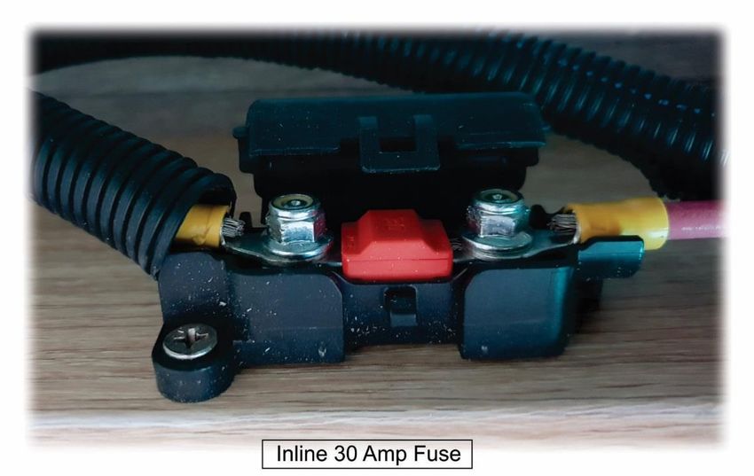
Owners Handbook

Coupling the caravan to your tow vehicle

Make sure that the caravan coupling height is approximately the same as the tow vehicle’s tow ball
height. Reverse the tow vehicle as close as possible to the coupling head of the caravan. While holding
the caravan in place, release the overrun handbrake lever, then by pulling on the grab handles
manoeuvre the caravan so that the coupling head is directly above the tow vehicle’s tow ball then
apply the caravan handbrake. Now pull up on the caravan coupling lock handle and lower the height
of the caravan by winding the jockey wheel down.

Once the caravan coupling has engaged the coupling lock handle will lock down into place. You will
see the green lock indicator will pop out at the front of the coupling head to indicate that the handle
has locked down into place. (As seen in fig 1 unlocked and fig 2. locked).
Clip the brake safety cable around the tow vehicle’s tow ball where it will hang loosely. The function
of this cable is to pull the handbrake lever up in the event that the caravan accidentally uncouples
from the tow vehicle when you pull away. Once the caravan is coupled securely you may release the
caravan overrun handbrake lever.

                                                                                           6|Page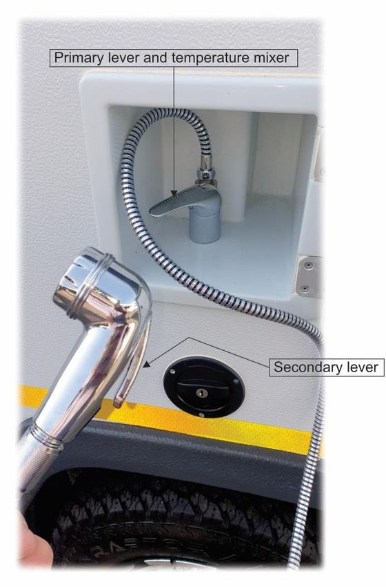
Owners Handbook

Wheels and Tyres
The tyres of the OKTO caravan should be inflated to 2.6 Bar, and checked before each trip.
It is advisable to inflate the tow vehicle as follows: Rear tyres 2.5 Bar and front tyres 2.2 Bar.
The wheel nuts should be checked and torqued to 95N.m before each trip. It is important to stop and
check wheel nuts of a new OKTO every 100km for the first 1000km. This will provide enough time for
the wheel nuts to seat into the rim.
If you need to change your wheel in the event of a puncture, follow the next procedure:

         •   Remove the spare wheel from its cradle as shown below.
         •   Place chocks on either side of the non-punctured wheel.
         •   Pull up the handbrake lever.
         •   Loosen the wheel nuts of the punctured wheel, but do not remove them yet.
         •   Wind the jockey wheel so that the nose of the caravan is as low as possible.
         •   Wind the rear corner steady on the side that has the punctured wheel down and exert
             approximately three winds of pressure onto the steady after it has touched the ground.
         •   Now wind up the jockey wheel as high as it can go. This should lift the punctured wheel
             off the ground.
         •   You can now loosen the wheel nut completely and remove them. Take off the wheel
             and fit the spare.
         •   Follow the same procedure but in reverse and make absolutely sure you have double
             checked that the wheel nuts are tight.

How to Remove the Spare Wheel

         •   Drop the nose of the caravan down as low as you can to provide enough space for the
             spare wheel to pass out underneath the wall of the caravan.
         •   Remove the clip and undo the locking fly-screw holding the spare wheel cradle in
             place.

                                                                                         7|Page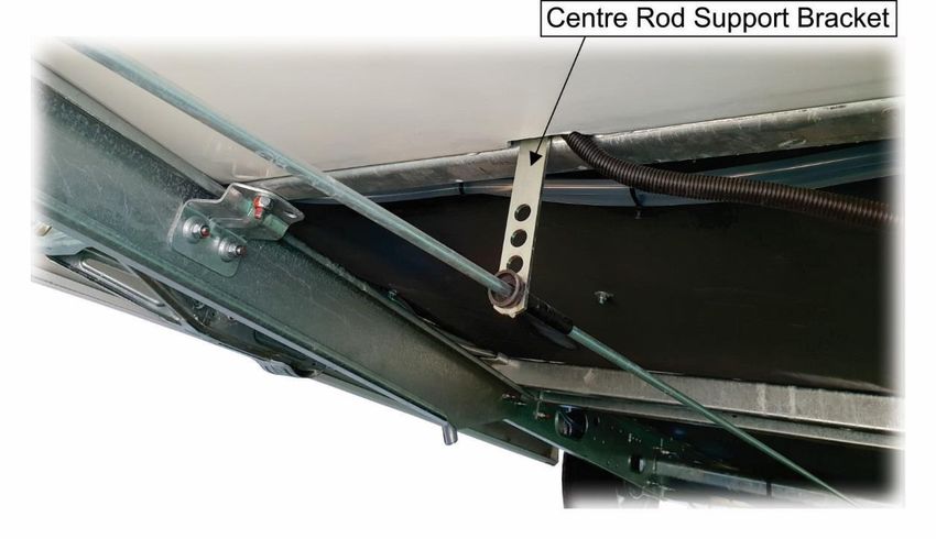
Owners Handbook

•   Reaching from the side of the caravan pull the handles gently towards yourself until
    the cradle drops to the ground. As shown in Fig. A. below.

•   Then move back and pull the handles towards yourself until the cradle is extended
    fully. You should then be able to reach the wing nut and retaining plate and remove
    the spare wheel from the cradle.

                                                                                8|Page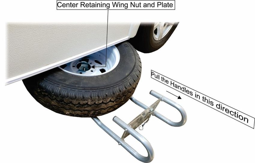
Owners Handbook

The Braking System
The OKTO caravan is fitted with AL-KO Automatic Reversing Hubs.
When the overrun handbrake is pulled up and the caravan is moving in a forward direction, the brake
shoes shift into a forward position in the hub and the caravan will brake. If the handbrake is pulled up
when the caravan is moving in a backward direction, the brake shoes shift into a reversing position in
the hub and release the brakes to approximately 60%. The caravan will continue in a backward
direction until the overrun brake lever shifts into an overrun position to activate the brakes fully. This
could take up to 1m. For this reason, it is advisable to place chocks behind the wheels before
uncoupling on a downhill. When you are travelling and you apply brakes in your car, the momentum
of the caravan causes the caravan’s coupling to push back and apply the caravan brakes. The shoes
will shift into a forward position braking the caravan. When you are reversing your combination, the
coupling will also push back and apply the caravan brakes, but because the caravan is moving in a
backward direction the shoes will once again shift into a reversing position in the hub enabling you to
reverse without the brakes being applied fully.

Setting the Brakes
The procedure below should only be attempted by a qualified person.
The brake setting should be done by an approved OKTO dealer while the caravan is still under warranty
period. Before adjusting the brakes, you need to roll the caravan in a forward direction and apply the
handbrake until the caravan stops. This will ensure that the brake shoes are in the correct position for
adjusting.
Procedure is as follows:
         •    Make sure that the caravan is parked on a level area, preferably not on grass or soil,
              then jack the caravan up so that both wheels are off the ground.
         •    Pull on the coupling head so that the coupling shaft is extended.
         •    Push the handbrake into a down position.
         •    Loosen all the lock nuts and release the tension of the centre rod and the brake cables
              at the centre equalizer bracket by loosening the adjustment nuts.

                                                                                              9|Page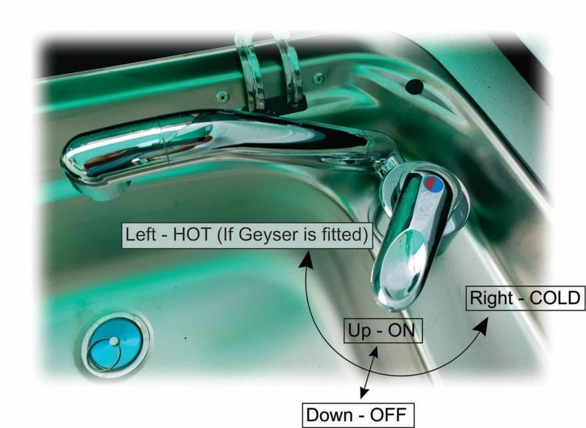
Owners Handbook

•   Remove the green dust plug in the adjusting hole at the rear of the brake drum. It is
    situated in the backing plate of the hub assembly.
•   Put a small flat screwdriver through the adjusting hole and click the adjusting nut while
    you are rotating the wheel in a forward direction.

•   Click the adjusting nut until the wheel stops turning.
•   Then click the adjusting nut in the opposite direction until the wheel turns freely. This
    should be approximately 5 clicks.
•   At the centre equalizer bracket, take up the slack on the brake cables and centre rod by
    adjusting the adjusting nuts and make sure the equalizer bracket is straight once done.
•   Pull the centre rod away from the coupling and check that there is 5mm play between
    the centre rod adjusting nut and the equalizer bracket.
•   Now lock all the lock nuts for the brake cables and centre rod.
•   Make sure that the centre rod support bracket at the front of the caravan is not bent
    and the cable can move freely.

                                                                                10 | P a g e
Owners Handbook
It is advisable to take your caravan for a road test after adjusting the brakes.
Make sure that the wheel nuts are torqued to 95N.m and the tyres are inflated to 2.6 Bar.
On the road test evaluate the following:
• The caravan brakes equally on both wheels. You will notice a side-ways pull if they
brake unevenly.
• The caravan does not sway excessively.
• The caravan does not bump up hard against the car when braking.
• The coupling does not knock excessively when pulling away.
• The brake drums will get hot when braking in town. Take the caravan on a 5km road
where no braking is required and check that brake drums cool down.
The Electrical System
Brief description
The OKTO caravan is fitted with a 220volt and 12volt system. The 220volt supplies a Victron Smart
charger, microwave and all the 220volt plug sockets. The charger monitors and keeps the
105 amp/hour battery in a fully charged state. The battery supplies the fridge, water pump and all the
interior and exterior LED Lights.
11 | P a g eOwners Handbook
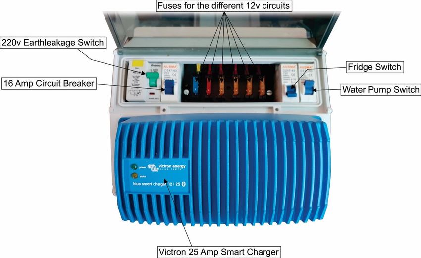
The Power Supply, Fuses and Switches
Above is a picture of the power supply unit which is located under the rear off-side dinette bunk. The
Power Supply Unit (PSU) is designed to be as user friendly and as robust as possible. The 220v is
channelled through an Earth leakage and circuit breaker. The PSU also distributes the 12v to the
various circuits, namely the LED lights, water pump, fridge and the exterior auxiliary cigarette lighter
socket and USB ports. The circuits are protected by inline blade fuses located in a fuse box on the PSU.
Below is a table indicating the fuse circuit and correct amperage. The fridge and water pump also have
their own circuit breakers as indicated in the picture above.
In addition to this fuse box OKTO have fitted a main fuse. This fuse is a 30amp Mini High Current Bolts
Fuse. This fuse is located behind the PSU and is accessible from the rear baggage compartment.
12 | P a g eOwners Handbook
The Victron Charger (only in Low Profile OKTO caravans) has Bluetooth and can be linked to Smart
devices such as Cell phones and tablets. The App is available on Play Store and is called
VictronConnect. Once the app is installed onto your device the app will prompt you for a password,
which is “000000”. The app will show you the condition of the battery, the Voltage available, the
Amperage being used by caravan and more.
Interior Lights
All the interior lights are LED lights and designed to draw as little current from the battery as possible
without sacrificing comfort. The furniture LED lights are neatly hidden away and will provide light into
the caravan living space when the doors are closed as well as into the lockers and cupboards when
the doors are open.
13 | P a g eOwners Handbook
The lights are controlled from a central panel located on the cupboard to the left as you enter the
caravan. In this panel there is a voltmeter that indicates how much voltage is available in the battery.
The reading and awning lights have their own switches and they will only operate once the fridge
circuit breaker is switched on. The awning light will require you to switch on the awning and step light
switch at the control panel first.
If you are not plugged into 220v it is advisable to switch off lights that are not in use. This will give you
a longer battery life. Here is a simple calculation to help you determine how much battery life you
have once the battery is fully charged.
Battery is a 102 amp/hr Deep Cycle Leisure battery. Available amperage would be 75% of the battery
capacity, therefore you have 75 amp/hour available before you need to charge the battery up again.
Based on the equation for Power Watts = Amp/h x Voltage below is a table to help you determine how
much battery life you have left.
14 | P a g eOwners Handbook
Battery and Battery Maintanance
Your OKTO caravan is fitted with a 12 volt Deep cycle Leisure battery with a capacity of 102amp/hours.
The battery is a sealed Lead/Acid battery and does not require topping up with distilled water.
Check that the battery terminal clamps are always correctly connected to the battery.
The positive clamp (red wire) needs to be clamped to the (+) post of the battery. The negative clamp
(black wire) needs to be clamped to the (-) post of the battery. Always connect the positive clamp first.
Always make sure that the lid of the battery box is in place.
It is advisable to keep the caravan plugged into 220v mains while the caravan is being stored.
The Victron Smart charger will manage the battery and ensure that the battery is kept in a fully charged
state. If you cannot store the caravan with the mains connected then it is important to disconnect the
battery terminals from the battery.
The caravan battery should however be charged up at least once a month for four days.
The battery should never be allowed to discharge fully. In the discharged state the lead plates of the
battery build-up a calcium layer. This layer thickens with time and if left too long, may cause
irreverasble damage to the battery in which case the battery may need replacing.
15 | P a g eOwners Handbook
Road Lights
All OKTO caravans are fitted with LED tail, indicator and stop lights. These LED lights require no
maintenance. The lights are all wired negative to earth and conform to SABS specifications.
Below is a diagram indicating the wiring of the 7-pin socket and plug.
OKTO does not use pin number 2 (aux) for the fridge, but instead your nearest OKTO dealers will be
able to fit a Brad Harris plug and wiring to your caravan so that you can charger the battery while you
are travelling. To do this you will also need an auto-electrician to fit a 12v Brad Harris supply plug to
your car. The fridge will then be powered by the caravan battery.
16 | P a g eOwners Handbook
The Water Sytem (Villa and Cabana)
Your OKTO is fitted with a 12 volt submersible water pump which fits into the 25ltr water container
located in the front nose storage area of the caravan. The water pump is activated by a micro-switch
situated in the taps of the caravan. The fuse for the water pump in situated in the fuse box on the
PSU and also has its own circuit breaker if you want to switch all the taps off.
If possible, it is recommended to travel and store the caravan with the water container empty.
Please do not let the water pump run when the water container is empty, as this could cause damage
to the pump.
Your OKTO Villa caravan is fitted with two mixer taps. The hot water will not work unless the caravan
has been fitted with a hot water geyser. The Villa can be fitted with an under-bed, 220v geyser.
Below is a diagram showing you the operation of the mixer tap.
17 | P a g eOwners Handbook
The Water Sytem (Gravellor)
The Gravellor range of OKTO caravans are fitted with a 80ltr under floor water tank.
It is recommended to fill the tank before switching on the pump or attempting any water operations.
When storing the caravan for extended periods, empty the water tank by running the hot or cold
water taps until the tank runs empty, you will then need to switch off the water pump. You could add
one bottle (500ml) of Miltons into the tank before emptying the tank, this will ensure that the pipes
are stored with a Miltons sterilising solution in them. The geyser cannot be drained.
This tank is filled via the lockable water inlet, situated above the off-side wheel.
18 | P a g eOwners Handbook
The water tank feeds an inline pressure pump which is located in the water tank protection plate.
Initially the pump will run in order to fill the water system. Once the water system is completely full,
the pump will turn off. The pump is fitted with a pressure switch enabling it to switch on and off as
the taps are being used. The pump supplies the cold water directly to the taps.
Hot water geyser
The pump also supplies the hot water to the taps via an inline gas/220v geyser.
The geyser is situated at the bottom of the front off-side wardrobe under the removable floor.
19 | P a g eOwners Handbook
Once the tank is full and before switching on the geyser, please make sure that the water runs out of
the hot side of the tap, strongly. This will indicate that the inline geyser is full.
The geyser swithes are found on the front lower panel of the wardrobe.
To start the geyser on 220v follow the next steps.
1. Make sure the outside geyser cover is removed and stored safely.
2. Make sure geyser is full.
3. Make sure the 220v is plugged in and on.
4. Switch the left hand switch to the “ON” position.
5. Switch the right hand switch to the “ELECTRIC” position.
There is no indicator light for the 220v and the water will take approximately 20min to warm up.
20 | P a g eOwners Handbook
To start the gesyer on gas follow the next steps.
1. Make sure the outside geyser cover is removed and stored safely.
2. Make sure the geyser is full.
3. Make sure you gas bottles have gas in and the regulator is screwed on.
4. Make sure the gas bottle is open.
5. Light the stove for approx 1 minute to draw the gas into the piping.
6. Switch the left hand switch to the “ON” position.
7. Switch the right hand switch to the “GAS” position.
The green LED in the centre will start flashing. Once the gas flame is ignited and burns constantly the
green LED will go off. If at any stage the green LED comes on again, without flashing, it is indicating
that the flame has blown out, or gas is empty. You would need to re-start the gas again as explained
above.
The outside shower hatch is fitted with a mixer tap and shower rose. To operate the water you open
the primary lever and set the required temperature as per the kitchen unit tap. Then push on the
secondary lever to release the water flow.
21 | P a g eOwners Handbook
Caravan windows
The caravan windows are acrylic and although they are extremely strong one needs to exercise caution
when cleaning the windows. Do not use any abrasive cleaners or brushes. Use only a soft cloth and a
gentle soap such as dish washing liquid or similar.
The operation of the window is exteremly simple. The window stays are self locking. When opening
the window simply open the latches that lock the window in place, then push the window open gently
and slowly until you hear a feint “click” sound. At this point you can stop pushing the window open
and let go, the window will stay open in the position. There are three opening positions. As shown
below:
To close the window simply push the window slightly further open and let the window drop back down
again. The latches have two closed positions. Position 1 in used when you want the window locked
closed but would like extra ventalation to flow through your caravan while camping. Position 2 is when
you want the window locked closed and sealed. Always ensure that position two is used before towing
your caravan.
22 | P a g eOwners Handbook
Specifications
Villa and
Villa Cabana En-Suite
Cabana Villa En-Suite Gravellor Gravellor Chateau
Chassis
Tyre Size 195 x 14C 195 x 14C 195 x 14C 218/80 x 15C 218/80 x 15C 195 x 14C
Rim 14" Alloy 14" Alloy 14" Alloy 15" Alloy 15" Alloy 14" Alloy
Rim PCD 5/114 5/114 5/114 5/114 5/114 5/114
Bearing outer 11949 11949 11949 32005 32005 11949
Bearing inner 67048 67048 67048 32007 32007 67048
Oil seal size 42x62x7 42x62x7 42x62x7 42x62x8 42x62x8 42x62x7
Tare Mass 1140kg 1200kg 1200kg 1235kg 1370kg 1580kg
Gross Mass 1500kg 1500kg 1500kg 1700kg 1700kg 1890kg
Payload 360kg 300kg 465kg 330kg 330kg 310kg
Length 5880mm 6850mm 6850mm 5880mm 6850mm 7840mm
Width 2362mm 2362mm 2362mm 2362mm 2362mm 2362mm
Roof down height 2020mm 2020mm 2020mm 2130mm 2130mm 2620mm
Interior
Bed size 1400mm x 1900mm 1400mm x 1900mm 1400mm x 1900mm 1400mm x 1900mm 1400mm x 1900mm 1520mm x 1900mm
Fridge Model DAC538 DAC538 DAC538 DAC538 DAC538 DAC449
Fridge Type 12v Defy 12v Defy 12v Defy 12v Defy 12v Defy 220v Defy
Fridge Capacity 127 ltr 127 ltr 127 ltr 127 ltr 127 ltr 142 ltr
Freezer Capacity 65 ltr 65 ltr 65 ltr 65 ltr 65 ltr 86 ltr
Total Capacity 192 ltr 192 ltr 192 ltr 192 ltr 192 ltr 228 ltr
Fridge Current
5amp on 12v 5amp on 12v 5amp on 12v 5amp on 12v 5amp on 12v 0.5amp on 220v
(While running)
12v 105amp/h 12v 105amp/h 12v 105amp/h 12v 105amp/h 12v 105amp/h 12v 40amp/hr
Battery
Deep Cycle Deep Cycle Deep Cycle Deep Cycle Deep Cycle Deep Cylce
12v Inline 12v Inline 12v Inline 12v Inline
Water pump 12v Submersible 12v Submersible
Pressure Pressure Pressure Pressure
Geyser None None Gas/220v Gas/220v Gas/220v Gas/220v
Water Tank 25 ltr Bottle 25 ltr Bottle 75 ltr Built-in 75 ltr Built-in 75 ltr Built-in 75 ltr Built-in
23 | P a g eYou can also read


