Model PD-5 Operator's Manual - (Physical Hard Drive Destroyer) - SEM Shred
←
→
Page content transcription
If your browser does not render page correctly, please read the page content below
Model PD-5
                 (Physical Hard Drive Destroyer)

                    Operator’s Manual

                       10620 Industrial Ave. Suite 100
                            Roseville CA 95678
                                   USA
                              (916) 784-0200
                              (800) 624-1903

4075-411 Rev A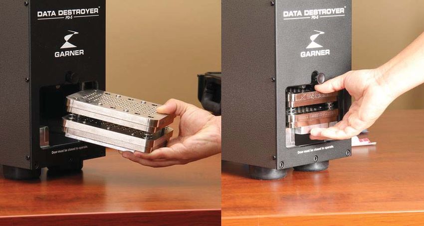
Table of Contents

Introduction.............................................................................................................................................................. 1

Important Instructions.............................................................................................................................................. 1

Factory Voltage ....................................................................................................................................................... 2

PD-5 Component Identification ............................................................................................................................... 4

   Front Panel Identification................................................................................................................................. 4
   Front Panel Description .................................................................................................................................... 4
   Inside Component Identification ...................................................................................................................... 5
   Inside Component Description ......................................................................................................................... 5

Operating the PD-5 ................................................................................................................................................. 6

   Initial Startup .................................................................................................................................................... 6
   Single Button Operation ................................................................................................................................... 6
   Display Messages............................................................................................................................................... 7
   Operating Environment .................................................................................................................................... 7
   Hard Drive Destruction..................................................................................................................................... 8
   Multiple Hard Drive Destruction ..................................................................................................................... 9
   Sold State Drive Destruction Using the Optional SSD-1 ............................................................................. 10
   Cleaning............................................................................................................................................................ 11
   Cleaning the Debris Tray ................................................................................................................................ 12
   Periodic Maintenance (Every 10,000 cycles) ................................................................................................. 13
       Greasing the Drive Shaft ............................................................................................................. 13

       Greasing the Vertical Crusher Slide Rails .................................................................................. 13

       Cleaning the Air Filters ................................................................................................................ 14

       Inspecting/Cleaning Exhaust Exit Fan ....................................................................................... 14

Parts List ............................................................................................................................................................... 15

Specifications ........................................................................................................................................................ 16

Warranty ................................................................................................................................................................ 17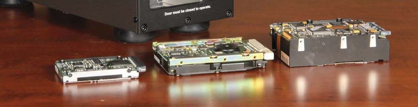
Introduction

Thank you for purchasing the PD-5 Physical Hard Drive Destroyer. The PD-5 will physically destroy working and
non-working hard disk drives (HDD), Network HDD, Half-Height HDD, Standard HDD and Laptop HDD by
bending, breaking and mangling data platters, pc boards and the frames of the hard drives.

The PD-5 is also designed to destroy solid state memory devises when used with the optional SSD Destroyer
accessory.

To ensure safe operation of the PD-5, please be sure to read and understand the contents of this operator’s
manual before operating the PD-5. We also advise you to keep this manual at hand for a quick reference in the
future.

Important Instructions

                       PLEASE READ THIS INFORMATION
                             BEFORE USING MODEL PD-5
This shipment was packaged and delivered to the carrier with utmost care to ensure safe delivery of goods to you,
our valued customer. PLEASE RETAIN ALL SHIPPING MATERIALS FOR FUTURE USE. FAILURE TO DO
SO MAY RESULT IN FREIGHT DAMAGE AND VOID WARRANTY.

In the event that you must transport your PD-5 to a different location or to the factory for repair service, you must
package it for safe delivery. Failure to do so may result in freight damage and will void the factory warranty.

Please contact Garner Products, Inc. at (800) 624-1903 for further information if required.

                                                     Page 1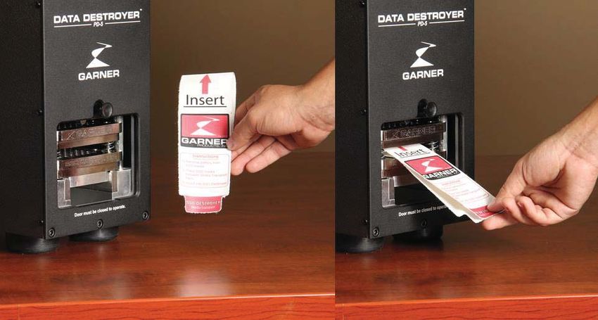
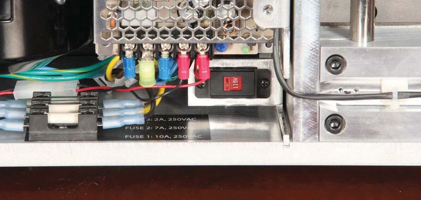
Factory Voltage

Each PD-5 comes with the above insert identifying the factory set voltage configuration. If the identified voltage
does not match your voltage mains, the correct voltage can be easily configured using the field selectable switch.
In the event the PD-5’s voltage setting needs to be changed, please perform the following steps:

      NOTE: BEFORE PERFORMING ANY MAINTENANCE ON THE PD-5, TURN THE UNIT OFF
AND UNPLUG THE POWER CORD FROM THE ELECTRICAL OUTLET.

    1) Remove 11 screws with T-20 Torx Driver from the chassis’ right side.

                                                   Page 2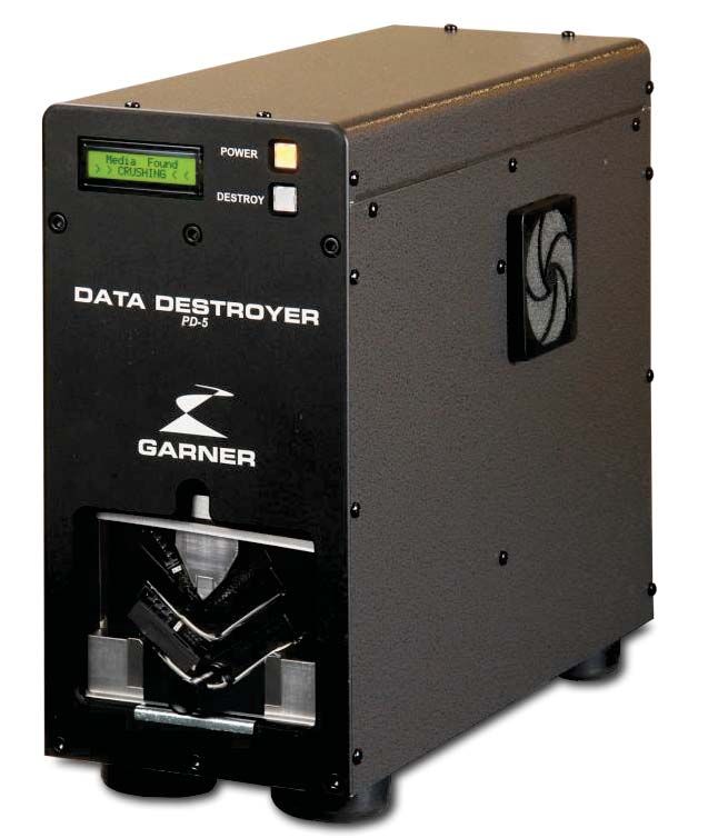
2) Carefully set the side panel perpendicular to the rear of the unit. Note: The ground cable attached to the
   side panel does not need to be removed.

3) Slide the red power setting switch to either the 115V or 230V setting. Choose the setting that most closely
   matches your power mains voltage.

4) Replace the side panel and secure with 11 screws using T-20 Torx Driver.

                                                Page 3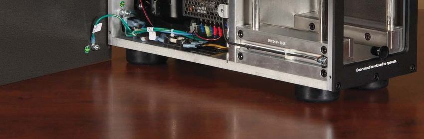
PD-5 Component Identification

  Front Panel Identification

  Front Panel Description
   1) Power Button       Applies power to the PD-5.
   2) LCD Display        32 Character LCD Display with counter for Session and Total.
   3) Destroy Button     Initiates the destruction function.
                         Prevents access to the HDD and destruction wedge during the destruction
                         process. If opened during the destruction process, the destruction wedge will
   4) Door/Door Handle
                         automatically stop. When the door is closed, the destruction wedge will return
                         to its home position.

                                             Page 4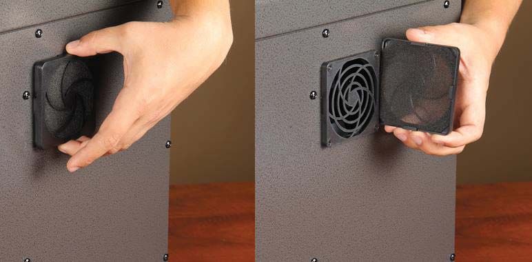
Inside Component Identification

Inside Component Description
                       The Destruction Wedge pushes down on the hard drive(s) bending and
1) Destruction Wedge   breaking the external and internal components, rendering the hard drive
                       inoperable.
                       Image shows the proper location of two 1” hard drives stacked on top of each
2) Hard Drives
                       other. Note: Hard drives are centered between the two Support Rails.
3) Support Rails       Supports and aligns the hard drive(s).
                       Removable tray helps collect hard drive debris caused by the destruction
4) Debris Tray
                       process. The Debris Tray can be easily lifted out and emptied.

                                         Page 5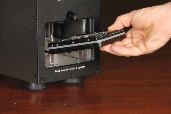
Operating the PD-5

  Initial Startup
   1)   Unpack the shipping carton/case and take out the PD-5 Physical Destroyer.
   2)   Make sure that the PD-5 has not been damaged during transportation.
   3)   Retain all shipping materials for possible future use.
   4)   Confirm power configuration as indicated on the attached sheet placed with this manual. Alternately, you
        can perform the steps in the “Factory Voltage” section of this manual.

  Single Button Operation
   1) Press the “Power” button. The LCD display will go through a start sequence which will display
      manufacturer information, software version, total number of cycles and then a ready screen. The
      destruction wedge returns to home position.
   2) Open door (The LCD display will show “Door Open”) and place the hard drive(s) on the Support Rails.
      Note: Center the hard drive between right and left Support Rails and ensure the hard drive(s) are
      positioned towards the back (Laptop drives can be oriented perpendicular to the standard drive orientation
      to mount on both support rails).
   3) Shut the door. The LCD will display “Ready Session: 0”.
   4) Press the “Destroy” button. The PD-5 will destroy the media in the destruction chamber and return to the
      home position, ready to destroy the next piece of media.
   5) Open the door and remove the hard drive(s) when the LCD displays “Ready Session: 1”, indicating the
      destruction process is complete and a cycle has been recorded.
   6) Repeat Steps 2-5 until the job is complete.

                                                  Page 6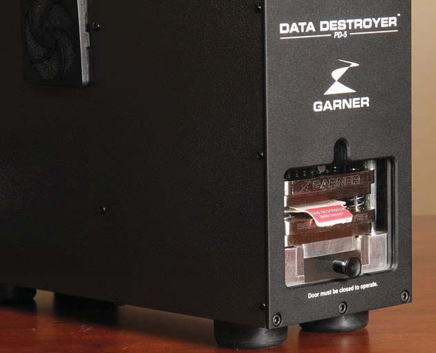
Display Messages
              Action                     LCD Display                           Description
                                        GARNER
       Step 1:                                                    Displays Manufacturer.
                                     PRODUCTS, INC.
         Press POWER
             button                   Garner Products
                                                                  Displays Destroyer Model.
                                       PD-5 Crusher

                                      FIRMWARE VER
                                                                  Displays current firmware version.
                                           ##
                                                                  Displays total erasing cycles.
                                          Total Count
                                                                  Number on left indicates number of
                                     #        −−      ##
                                                                  times the counter reached 50,000.
                                                                  Ready for media to be placed in the
                                            Ready                 destruction chamber.
                                          Session = 0             Counter for erase cycles from power
                                                                  up.
                                                                  Indicates media safety door is open –
       Step 2:                            Door Open               this is normal when inserting media
          Insert media                                            to be destroyed.
       Step 3:
          Press “Destroy”                Finding Media            Destroy cycle has started.

                                          Media Found             PD-5 switches from high speed to
                                         > CRUSHING <             high torque to crush media.

                                                                  PD-5 has used maximum force and
                                         MAX FORCE
                                                                  will stop and return to home.

                                                                  Indicates PD-5 is returning to home
                                          Going Home
                                                                  position (Wedge at MAX height).

                                            Ready                 Destroy cycle is complete. Open
       Step 4:
                                          Session = 1             door and remove media.
                                                                  Every 10,000 cycles, the PD-5
       Periodic                      Service Required
                                                                  requires service. See page 13 of
       Maintenance:                See Operator’s Manual
                                                                  manual for details

   Operating Environment
Do not use or keep the PD-5 in environments with excessive heat, cold, humidity, or dust.
Use caution when bringing the PD-5 from a cold environment into a warm environment. If moisture has
accumulated due to a sudden change of temperature, wait (1) hour until moisture has completely dissipated
before operating the PD-5.

Place the PD-5 on a secure and stable horizontal surface. Position the PD-5 to allow proper air flow from the
side air inlets and the rear exhaust. A minimum clearance of 6 inches from any obstructing wall or solid surface
is recommended.
                                                  Page 7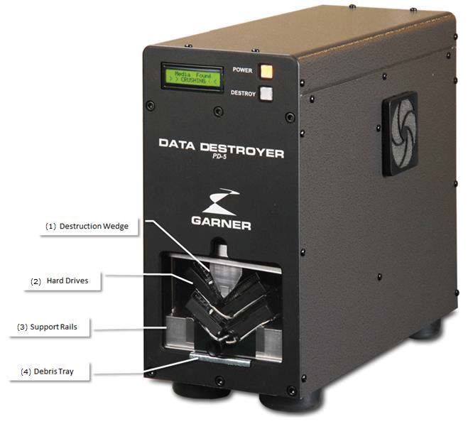
Hard Drive Destruction
The PD-5 is designed to destroy many different formats of hard drives including: laptop drives, standard 1” drives,
and 1.5” drives.

To destroy hard drives:
    1) Press Power button.
    2) Remove mounting hardware from hard drive that would cause the media door not to close.
    3) Lift door, and insert hard drive into PD-5.

    4) Close door and press the “Destroy” button to activate destruction cycle.
    5) Open Door and remove the crushed hard drive(s).

                                                    Page 8
Multiple Hard Drive Destruction
The most efficient way of destroying hard drives is to destroy multiple hard drives at one time. The PD-5 is
designed to destroy up to (8) laptop drives or (2) standard 1” drives at one time.
Single Hard Drive Destruction
Multiple Hard Drive Destruction
(Note that the image on the left is
of 8 laptop hard drives loaded
perpendicular to the support rails)
Page 9Sold State Drive Destruction Using the Optional SSD-1
1) Lift door, and insert SSD-1 solid state destroyer into PD-5
2) Place SSD’s, USB drives, compact flash disks, cameras, hard drive controller boards and cell phones
REMOVE BATTERY FIRST) in between the panels of the SSD Media Transport Sleeve and slide
(R
the sleeve into the opening within the SSD Destroyer.
3) Close the door and press the “Destroy” button. The PD-5 and the SSD Destroyer will destroy the
media and return to home position to be ready to destroy the next piece of media.
Page 104) Open the door and remove the media by gripping the end of the SSD Media Transport Sleeve. The
SSD Media Transport Sleeve is tough and designed for multiple cycles. The LCD displays “Ready
Session: 1”, indicating the destruction process is complete and a cycle has been recorded. Remove
SSD destroyer if desired.
Cleaning
Wipe dirt off with a soft and dry cloth. Do not use chemicals or solvents.
Note: Use caution when cleaning the unit as some debris is sharp and may contain glass.
To achieve proper hard drive placement, sweep or vacuum Hard Drive debris from the inside of the PD-5. Empty
debris from the Debris Tray and remove any debris that has remained on the Support Rails. Excess debris will
alter the placement of the HDD and may cause damage to the PD-5. (See “Cleaning the Debris Tray”, page 12.)
Page 11Cleaning the Debris Tray
During the destruction process small fragments of the hard drive may be left on the Support Rails and in
the Debris Tray. Sweep or vacuuming the fragments from the Support Rails into Debris Tray located on
the bottom of the Destruction Chamber in between the Support Rails of the PD-5. When enough debris
has accumulated, the Debris Tray needs to be removed and emptied.
1) Make sure destruction wedge has returned to the top or home position. Wait for motor to stop.
2) Open Door.
3) Sweep debris from side rails into Debris Tray.
4) Lift and remove Debris Tray.
5) Empty Debris Tray into trash container.
6) Check bottom of crush chamber for additional debris.
If additional debris is found use a small brush to move additional debris to the front
of the destruction chamber. There are two holes that allow debris to be swept out
of the floor of the destruction chamber. Note: Placing the debris tray under the
front of the PD-5 will catch the debris as it falls from the two holes in the front of the
destruction chamber. (See “Cleaning Tips” below).
7) Replace the Debris Tray and resume the destruction process.
Note: Make sure that the Debris Tray is inserted all the way to the back of the chamber or the door will not
shut completely.
Cleaning Tip: You can use the debris tray itself to clear remaining debris from the bottom of the PD-5 as
demonstrated in the images below.
Page 12Periodic Maintenance (Every 10,000 cycles)
NOTE: BEFORE PERFORMING ANY MAINTENANCE ON THE PD-5, TURN THE UNIT OFF
AND UNPLUG THE POWER CORD FROM THE ELECTRICAL OUTLET.
Greasing the Drive Shaft
Remove the left side of the PD-5 by removing 11 screws with a T-20 torx driver. Locate the knurled brass knob
and rotate ½ turn clockwise. This will automatically apply grease to the drive shaft.
Greasing the Vertical Crusher Slide Rails
Lift the door and apply a small coat of white lithium grease on each vertical crusher slide rail with a Q-tip. Spread
until a thin layer of grease coats the entire rail. Repeat on each of the four rails.
Page 13Cleaning the Air Filters
Remove the side air filter housing by hand and clean any major debris off foam filter. Use canned-air to blast any
dust or debris from filter. Replace foam filter in plastic housing and firmly reattach to side panel by ensuring all 4
plastic tabs securely latch to adjacent filter frame.
Inspecting/Cleaning Exhaust Exit Fan
Inspect the rear panel of the PD-5 to ensure exit fan is free of dust and debris. If any dust or debris is found,
clean/remove it from fan assembly.
Page 14Parts List
Part Number Description
2500-091B Rail, door slide
2600-013 Fan, 24vdc
2600-014 Filter assy
2600-015 Finger guard, fan
2825-278 Bolt, shoulder 3/8 dia .75
2825-289 Knob, plastic
2825-294A Tray, debris
335-0010 Fuseholder, 3AG
356-0001 SS Relay, 240VAC 40A
3500-059B Gear, 48 tooth
3500-060E Gear, 16 tooth
3500-064E Shaft, gear
3500-066D Gear, spur 60 tooth
3500-068 Motor, 110/115
4000-007 Power Supply, 90-264VAC
4300-026 Fuse, 10A 250V slow blow
4075-270H Manual, operation PD-5
4500-023 Relay, SS SPST 5A
4700-045 Resistor, R5 50W
5100-001 Pushbutton switch
5100-034 Switch, power rocker
SA1400-216B Rail, crush chamber
MS2400-058C Rail, media support
SA2500-059B Plate, compression
MS2400-059B Screw, acme
MS5400-006B Wedge, media destroyer
SA1400-215C Plate, crush chamber side
SA1400-258B Door, crush chamber
SA1700-205D PCB, main control populated
SA1700-206B PCB, control panel populated
SA1700-207G PCB, chamber sense
SA2400-060B Bar, media stop
SA2400-062C Rail, bumper
SA2500-090B Bracket, index cntr
SA3500-070C Index card, motor
SA6000-085A Harness, wiring PD-5
Page 15Specifications
Power Supply Standard Factory Setting: 120V ±5% 50/60 Hz
Field Selectable: (100-240V) (50 or 60 Hz)
Power Consumption 1.5A Operating, 7A MAX @ 120VAC
Cycle Time PD-5 Standard Model Full Cycle: ~ 20 seconds
Destroy Cycle: ~ 10 seconds
PD-5 Standard Model Capacity 2.5" and 3.5" Hard Drives.
Disk drives up to 1.66" high.
Two 1” high standard hard disk drives.
Up to eight laptop hard disk drives.
Operating Environment 41°F - 104°F (5°C - 40°C), Humidity: 10 to 80%
(Non-Condensing)
Physical Weight PD-5: Net 72 lbs. (32.66Kg)
Case: 23 lbs. (10.43 Kg)
Shipping Weight 82 lbs. (37.19 Kg)
Physical Dimensions PD-5: 18.0 in. (L) x 7.0 in. (W) x 14.5 in. (H)
Case: 17 in. (W) x 24.5 in. (L) x22.5 in. (H)
Shipping Dimensions 24 in. (L) x 12 in. (W) x 20 in. (H)
Warranty 1 Year Parts and Labor Limited Warranty
Duty Cycle Continuous*
* Ambient temperatures above 75 degrees F will have an effect on duty cycle.
10620 Industrial Ave. Suite 100
Roseville CA 95678
(916) 784-0200
(800) 624-1903
www.garner-products.com
Page 16Warranty
GARNER PRODUCTS, INC. LIMITED WARRANTY
AND
WARRANTY RETURN POLICY
Garner Products, Inc. (“Garner”) warrants this Garner-branded product (“Product”) against defects in materials and
workmanship for a period of ONE (1) YEAR from the date of purchase by the original end-user (“end-user”) as evidenced by
end-user’s packing slip or invoice (“Warranty Period”). No Product may be returned except upon prior written permission by
Garner and shipment to factory with transportation charges prepaid.
If a defect arises and a valid claim is received within the Warranty Period, at its option, Garner will either: (1) repair the Product,
(2) exchange the Product, or (3) request that end-user replace defective parts with new or refurbished user-installable parts that
Garner provides in fulfillment of its warranty obligations. A replacement Product or part, including a user-installable part that has
been installed in accordance with instructions provided by Garner, assumes the remaining warranty of the original Product or
ninety (90) days from the date of replacement or repair, whichever provides longer coverage.
Garner’s liability under this warranty is limited to Garner’s cost of replacing any part or Product found by Garner to be defective
and shall not exceed the original purchase price of the defective Product. End-user’s sole and exclusive remedy against Garner
shall be for the replacement of the defective part or Product as provided herein.
This warranty does not apply to: (a) cosmetic damage, including but not limited to scratches, dents and broken plastic; (b)
freight damage; (c) consumable parts; (d) normal wear and tear; (e) damage caused by accident, abuse, inadequate wiring,
power surge, rust, corrosion, neglect, misuse, water, fire, earthquake or other external causes; (f) damage caused by operating
the Product outside the permitted or intended uses described by Garner; (g) damage caused by service performed by anyone
who is not a representative of Garner or a Garner authorized service provider; (h) a Product or part that has been modified to
alter functionality or capability without the written permission of Garner; or (i) if any Garner serial number has been removed or
defaced.
No Garner dealer or reseller is authorized to make any modification, extension, or addition to this warranty.
DISCLAIMER
THIS WARRANTY SET FORTH ABOVE IS EXCLUSIVE AND IN LIEU OF ALL OTHER WARRANTIES, EXPRESS OR
IMPLIED, INCLUDING ALL IMPLIED WARRANTIES OF MERCHANTABILITY AND FITNESS FOR A PARTICULAR
PURPOSE OR USE. GARNER’S MAXIMUM LIABILITY SHALL BE LIMITED TO THE PURCHASE PRICE OF THE
PRODUCT.
LIMITATION OF LIABILITY
IN NO EVENT SHALL GARNER BE LIABLE TO ANY PARTY FOR ANY SPECIAL, INCIDENTAL OR CONSEQUENTIAL
DAMAGES OF ANY NATURE THAT ARISE FROM ANY BREACH OF WARRANTY OR CONDITION, OR UNDER ANY
OTHER LEGAL THEORY, INCLUDING BUT NOT LIMITED TO LOSS OF USE, LOSS OF REVENUE, LOSS OF ACTUAL OR
ANTICIPATED PROFITS, LOSS OF BUSINESS, OR LOSS OF GOODWILL.
GARNER’S MAXIMUM LIABILITY SHALL NOT EXCEED THE PURCHASE PRICE OF THE PRODUCT WHICH GIVES RISE
TO THE CLAIM. END-USER’S SOLE AND EXCLUSIVE REMEDY FOR ANY CAUSE OF ACTION, WHETHER ARISING
FROM BREACH OF CONTRACT OR TORT, IS A CLAIM FOR DAMAGES WHICH IN NO EVENT WILL EXCEED THE PRICE
OF THE SPECIFIC PRODUCT AS TO WHICH THE CLAIM IS MADE.
WARRANTY RETURN POLICY
If a problem occurs with this Product, contact Garner directly by Email at Info@Garner-Products.com or by phone at (916)
784-0200 to obtain technical support and/or to get a Return Authorization Number (RA#).
All returns must be specifically authorized by Garner prior to shipment and returned to Garner FREIGHT PREPAID with the RA#
marked prominently near the shipping label.
Garner recommends using the original shipping container to securely package the Product. It is end-user’s responsibility to
ensure the Product is packaged properly to prevent damage during transit to Garner. Garner will provide product packaging to
end-user at end-user’s request and expense.
Enclose proper documentation, including RA#, the return address, a name and phone number of the contact person, the serial
number of the merchandise being returned and a description of the reason for the return. Omission of any of this information
may delay service. Garner recommends end-user insure the shipment; otherwise end-user accepts the risk if Product is lost or
damaged in shipment.
Garner will pay to ship the repaired or replacement Product to end-user’s shipping dock if end-user’s delivery address is in the
United States (excluding Puerto Rico and U.S. possessions and territories); otherwise Garner will ship the Product to end-user
freight collect. Garner will select method for return shipment. Alternate shipment methods may be made at end-user’s expense.
Page 17You can also read