User Guide Falcon 3-axis Non Contact Measurement Systems - Vision Engineering
←
→
Page content transcription
If your browser does not render page correctly, please read the page content below
User Guide Falcon 3-axis Non Contact Measurement Systems
INTRODUCTION
Falcon 3-axis
INTRODUCTION Non Contact Measurement Systems
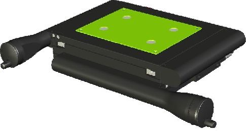
Vision Engineering's Falcon is a compact 3-axis non-contact semi-automated measurement system, designed to give
cost-effective accurate results.
The repeatable 5-position zoom optics provide the user with a high resolution clear image of intricate parts. Accurate
repeatable results are achieved in X and Y, by the NLEC calibrated stage, and in Z by the unique camera iris control
reducing the depth of field.
Health & Safety
Vision Engineering and its products conforms to the requirements of the EC Directives on Waste Electrical and
Electronic Equipment (WEEE) and Restriction of Hazardous Substances (RoHS).
EN61326-1:2006
FCC Part 15
EN60950-1:2001
WARNING: ALL EQUIPMENT PLUGGED INTO THIS UNIT MUST BE APPROVED TO EN60950-1:2001 AND
CHECK CURRENT RATING OF OUTPUT SOCKET IF USED.
FALCON EQUIPMENT – WARNING
This warning refers to CNC systems
Warning – hazardous moving parts.
To avoid entrapment keep fingers and other body
part away from moving parts
To stop all CNC movement in an emergency situation move the joystick in ANY direction.
This will interrupt the CNC programme and stop any movement.
In the case of a system failure or crash, to stop the CNC movement switch the Control Power Supply off or switch off
the mains power to the system.UNPACKING
Unpacking
UNPACKING the Falcon stand (all systems)
1 2 3
Ò
Falcon with M3 software (manual) system by box content
Box 1 Stand, accessory box (objectives, ringlight, cable (x1))
Box 2 M3 software preinstalled PC, keyboard, mouse
Box 3 Touch Screen Monitor
Box 4 M3 USB interface box
Box 5 Manual stage (150mm x 100mm or 150mm x 150mm), control unit, cables (x5)
Falcon with M3-CNC software (motorised) system by box content
Box 1 Stand, accessory box (objectives, ringlight, cable (x1))
Box 2 M3-CNC software preinstalled PC, keyboard, mouse
Box 3 Touch Screen Monitor
Box 4 M3-CNC USB interface box
Box 5 Motorised stage (150mm x 150mm), joystick, CNC control unit, cables (x7)
Falcon QC-5000 (manual) system by box content
Box 1 Stand, accessory box (objectives, ringlight, cable (x1))
Box 2 QC-5000 PC, keyboard, mouse
Box 3 Monitor
Box 4 Manual stage (150mm x 150mm or 150mm x 100mm), control unit, cables (x4)
Falcon QC-5000 (motorised) system by box content
Box 1 Stand, accessory box (objectives, ringlight, cable (x1))
Box 2 QC-5000 PC, keyboard, mouse
Box 3 Monitor
Box 4 Motorised stage (150mm x 150mm), joystick, CNC control unit, cables (x6)CONTENTS FALCON EQUIPMENT CONTENTS Stand & objectives 1 Stage 1 Control units 2 M3 microprocessor 2 QC-5000 PC 2 ASSEMBLY Removing the transit protection 3 Attaching the LED array 3 Stage assembly (150mm x 150mm) - manual and motorised 4 Stage assembly (150mm x 100mm) 5 Objective lens attachment 6 Cable connection M3-VED (manual systems) 7 Cable connection M3-CNC (CNC systems) 7 Cable connection QC-5000 (manual systems) 8 Cable connection QC-5000 (CNC systems) 8 Z-Axis mouse setup 9 Connection 9 Calibration 9 Speed setting 10 Stage alignment 11 Securing the stage (150mm x 150mm) 11 Securing the stage (150mm x 100mm) 12 Fitting the stage glass 13 Stage glass levelling 13 PRODUCT FAMILY Falcon family tree 14 OPERATION & SETUP Main system controls 15 HOW TO USE YOUR FALCON MEASURING SYSTEM Measurement system settings and advanced features 16 Iris controls 16 Objective lens 17 Best practice 17 Getting the most from your Falcon 18 ROUTINE MAINTENANCE Substage LED changing 19 LED Ringlight replacement 19 SERVICE & CALIBRATION RECORD WARRANTY
FALCON EQUIPMENT

Stand  & objectives
FALCON EQUIPMENT

                  [                       Ò       4

1 Stand

2 Low magnification objective lens

3 High magnification objective lens

4 LED ringlight
                                                                                               1
5 Toolkit

                                          2

                                              3                       5
                                      1
Stage
1 150mm x 100mm manual stage                                                            2

2 150mm x 100mm adapter

3 150mm x 150mm manual stage
                                          3
4 150mm x 150mm motorised stage

                  4

                                                                                                     1
www.visioneng.com/support                             Falcon 3-axis Non Contact Measurement System
FALCON EQUIPMENT
1
Control units
1 Manual control power supply unit
(z-axis rocker switch or mouse
control)
2 Z-Axis mouse controller
3 CNC control power supply 3
unit & joystick
(motorised stage only)
4 Trackerball controller
(option for motorised stage only) 2
4
M3 microprocessor
M3 USB interface unit
Note: Please ensure your Windows® operating
system is kept up to date through
Windows® Update.
Note: In applications where the USB
signal/power is weak (i.e. with long leads
and some laptops) we recommend using a
powered hub or repeater cable (available
from your local PC retailer).
2 1
QC-5000 PC
1 QC-5000 PC
2 Monitor
3 Keyboard and mouse
Note: Please ensure your Windows®
operating system is kept up to
date through Windows®
Update.
3
2
Falcon 3-axis Non Contact Measurement System www.visioneng.com/supportASSEMBLY
Removing
ASSEMBLY the transit protection
[ Ò
u Remove the 3 securing screws u and then remove
the transit plate v.
w
u Unscrew and remove the rear transit bolt w.
u
Note: Keep the transit protection for
future transport of your Falcon.
It is highly recommended that
you refit the transit protection
whenever you transport your
system. v
Attaching the LED array
u
u Connect the flying lead socket u into the
fixed plug v on the LED array w.
v
u Carefully position the array and secure it by
tightening the single securing screw x using w
the Allen key supplied.
x
3
www.visioneng.com/support Falcon 3-axis Non Contact Measurement SystemASSEMBLY
Stage assembly (150mm x 150mm) -
manual and motorised
Note: Although the manual stage is illustrated, the
assembly procedure for the motorised stage is
identical (with the exception of the transit clamps -
see below)
u Use the stand's levelling foot u to ensure the
base is stable. y y
y
u Place the stage on the stand ensuring
the retractable foot (position B4 in
diagram v below) is fully retracted.
u Check the stand base plate w and the x
underside of the 150mm x 150mm stage x
are clean and free of any debris.
u Loosely fit the stage bolts y in position B1, B2
and B3 (also in diagram v) to a light (finger tight)
tension.
w
Note: Do not tighten the stage bolts as the
u
stage will need to be aligned (see page 11).
Column
v
B4 B2
Stage Assembly
B1 B3
Logo
u Remove all red transit clamps from the stage.
Manual Stage
Motorised Stage
4
Falcon 3-axis Non Contact Measurement System www.visioneng.com/supportASSEMBLY
Stage assembly (150mm x 100mm)
u Check the adjustable pad (foot) u on the stage adaptor is
retracted up into the plate. The adjustable pad is controlled by
the screw in the rear left hole in the plate.
u Check the stand mounting pads v and the underside of the
plate w are clean and free of debris.
u Place the adaptor plate on the stand base mountings and
align the three bolt holes x, insert the bolts and do x x
them up until they touch down. Then, back them
off a small amount, when all the bolts are in.
x
Tighten them to torque setting of 2.9Nm
which is approximately equal to bolt touch
w
down, plus a quarter of a turn. The bolts
should be tightened in the following sequence: v
front right, front left and then back right.
u Once the bolts are done up, the adjustable pad
should be set. To do this, use a small screwdriver
to just touch down the screw. DO NOT then add
any torque to the screw, as this could distort the
base plate. The screw has a special coating which
prevents it from working loose. u
u Fit the stage in accordance with the instructions.
u Remove all red transit protection from the
stage.
y
{ {
u Check the adjustable pad y on {
the stage is retracted up into the
stage bottom plate. The adjustable pad is
controlled by the screw in the rear left hole in the z
aperture under the stage glass.
u Check the top of the adapter z and the underside of the
stage are clean and free of any debris.
u Place the stage on the adapter and align the three bolt
holes {. Screw in the Allen bolts (using the Allen key
provided) but DO NOT tighten them at this time.
5
www.visioneng.com/support Falcon 3-axis Non Contact Measurement SystemASSEMBLY
Objective lens attachment
u Place the objective lens u up into the head v and screw it into
position.
u For further information, see Objective lens on page 17.
v
u
6
Falcon 3-axis Non Contact Measurement System www.visioneng.com/supportASSEMBLY
All connectors must be engaged fully and secured with the screws.
Note: In applications where the USB signal/power is weak (i.e. with long leads and some laptops) we
recommend using a powered hub or repeater cable (available from your local PC retailer).
Note: Please ensure your Windows® operating system is kept up to date through Windows® Update.
Cable connection M3-VED (manual systems)
KEY MAINS POWER IN
Mains Power
Display PC USB
Lighting/Power
LIGHT CONTROL
X, Y and Z
PC USB X Y Z
PC USB
X-AXIS
USB
Y-AXIS
LIGHTING / POWER
Z-AXIS MOUSE
Z-AXIS DISPLAY I/O STAND I/O MOUSE
CONTROLLER
MAINS POWER IN
WARNING:To comply with safety regulations, easy access to the mains socket must be maintained.
Cable connection M3-CNC (CNC systems)
KEY
Mains Power MAINS POWER IN
Display
Lighting/Power PC USB
X, Y and Z
Joystick
Trackerball LIGHT CONTROL CNC < < <
(optional)
CNC
X Y Z
PC USB
X-AXIS PC USB
USB
Y-AXIS
LIGHTING / POWER DISPLAY I/O STAND I/O
X
Y
Z-AXIS JOYSTICK CNC < < <
MAINS POWER IN
WARNING:To comply with safety regulations, easy access to the mains socket must be maintained.
7
www.visioneng.com/support Falcon 3-axis Non Contact Measurement SystemASSEMBLY
All connectors must be engaged fully and secured with the screws.
Cable connection QC-5000 (manual systems)
KEY
Mains Power USB PC
(rear)
USB
Display
Lighting/Power DISPLAY I/O
X, Y and Z FOOTSWITCH
(optional)
Z Y X
Footswitch
X-AXIS
USB
Y-AXIS
LIGHTING / POWER
Z-AXIS MOUSE
Z-AXIS
DISPLAY I/O STAND I/O MOUSE
CONTROLLER
MAINS POWER IN
WARNING:To comply with safety regulations, easy access to the mains socket must be maintained.
WARNING:T o comply with safety regulations, easy access to the mains socket must be maintained.
Cable connection QC-5000 (CNC systems)
KEY
Mains Power
USB
Display USB PC
(rear)
Lighting/Power
X, Y and Z
DISPLAY I/O
Joystick
CNC
Footswitch FOOTSWITCH
Z Y X (optional)
CNC
USB
LIGHTING/POWER
DISPLAY I/O STAND I/O
Z-AXIS
X
Y
JOYSTICK CNC < < <
MAINS POWER IN
WARNING: To comply with safety regulations, easy access to the mains socket must be maintained.
WARNING:To comply with safety regulations, easy access to the mains socket must be maintained.
8
Falcon 3-axis Non Contact Measurement System www.visioneng.com/supportASSEMBLY
Z-Axis mouse setup
Connection v
u
u Plug the supplied Z-Axis mouse controller into
the USB port u at the rear of the box.
Note: Only use the mouse supplied. The
mouse supplied is an enhanced
mouse. A mouse with a
non-enhanced interface will not
work.
u Set the z-axis motion switch v to ON to enable
mouse controller and disable the rocker switch.
Calibration
Note: It is recommended that this calibration is repeated as part of the system scheduled service and
calibration.
A function has been provided to remove MOST of the backlash evident when changing direction.
u Remove the calibration cover panel u from the
u
rear of the control unit.
v
u Ensure all DIP switches v are set to OFF (up
position).
u Scroll the mouse wheel away from you until
movement is seen at the DRO scale readout.
u Switch DIP switch 5 ON (down position).
u Scroll the mouse wheel towards you, one click at
a time, until movement is seen at the DRO.
Please be patient as this may take a while.
u Switch DIP switch 5 OFF and switch DIP switch 6 ON.
u Scroll the mouse wheel away from you, one click at a time, until movement is seen at the DRO. Please be patient
as this may take a while.
u When movement is detected, switch DIP switch 6 OFF.
u Ensure to reset the DIP switch to the required speed setting (see Speed setting on page 10).
9
www.visioneng.com/support Falcon 3-axis Non Contact Measurement SystemASSEMBLY
Speed setting
The control power supply unit has two speed settings depending on your preferences and if you are using a HI
magnification (x20 – x100) or LOW magnification (x10 – x50) objective.
The default setting is for HI magnification. The speed setting can be set by adjusting the position of DIP switch No.1
as follows:
u Remove the calibration cover panel u from the u
rear of the control unit.
u Set the position of DIP switch 1 as required
according to the table below.
1 2 3 4 5 6
HI magnification
ON OFF ON OFF OFF OFF
(default)
LOW
OFF OFF ON OFF OFF OFF
magnification
u Refit cover panel.
10
Falcon 3-axis Non Contact Measurement System www.visioneng.com/supportASSEMBLY
Stage alignment
u Turn on the Falcon using the switch on the front of the u
control unit - see page 15.
u Switch on the measurement PC supplied and follow
on screen instructions for crossing reference marks.
u If a high magnification objective is being used, set the
magnification control u to 2. If a low magnification
objective is being used, set the control to 4.
u Focus on the three horizontal lines in the centre of the alignment
plate attached to the stage.
u Rotate the stage by hand until the horizontal lines are parallel to the
horizontal crosshair on the measurement PC supplied.
u Use the X axis control v to check reference lines remain parallel with the crosshair. v
IMPORTANT: Before the alignment plate can be removed the relevant stage securing procedure should
be carried out (see below or page 12 as appropriate).
Securing the stage (150mm x 150mm)
With the stage assembled (see page 4) and aligned
(see above), secure the stage as follows:
w w
u Being careful not to move the stage,
loosen the floating stage foot
securing screw u. v
u Insert and screw in the last stage bolt
w w
v and tighten until finger tight.
u Use the Allen key supplied to
progressively tighten all 4 screws u v
through the appropriate holes w in the
alignment plate in the numbered sequence
(shown in the diagram x below) to a torque of
2.8Nm.
u Lightly tighten the floating stage foot securing screw.
u Remove the alignment plate. x Column
Note: If you need to remove the stage for any reason,
B4 B2
re-attach the alignment plate and ensure the
horizontal lines are parallel to the horizontal
Stage Assembly
crosshair before removing the stage.
B1 B3
Logo
11
www.visioneng.com/support Falcon 3-axis Non Contact Measurement SystemASSEMBLY
Securing the stage (150mm x 100mm)
With the stage assembled (see page 5) and aligned (see page 11), secure the stage as follows:
u Use the Allen key supplied to progressively tighten all 3
screws through the appropriate holes u in the alignment u
plate in the numbered sequence (shown in the diagram v
below) to a torque of 2.8Nm. u u
u Set the adjustable pad w using a flat headed screwdriver.
Adjust the screw until it just touches down - DO NOT USE
FORCE! If this screw is over tightened, the base plate will w
distort.
u Remove the alignment plate.
Note: If you need to remove the stage for any
reason, re-attach the alignment plate
and ensure the horizontal lines are parallel
to the horizontal crosshair before removing
the stage.
Column
v
B2
Stage Assembly
B1 B3
Logo
12
Falcon 3-axis Non Contact Measurement System www.visioneng.com/supportASSEMBLY
Fitting the stage glass
u
u Fit the stage glass u into its recess, taking care to locate it
against the location springs and on to the supports v.
Note: The above procedure should be used for both
v
types of stage.
v v
v
Stage glass levelling
u Use the X axis u and Y axis v controls to bring the rear right-hand corner of the stage glass (fixed corner) w
into view.
w
u Use the stage focus control to bring the glass surface into sharp focus.
u Use the axis controls to bring the front right-hand corner into
view. Use the relevant adjustable
glass support to bring the surface of the glass
into sharp focus.
u Repeat for the remaining 2 corners.
u Repeat the above steps if necessary until all 4
corners are in focus.
v
u
13
www.visioneng.com/support Falcon 3-axis Non Contact Measurement SystemPRODUCT FAMILY
Falcon family tree
PRODUCT FAMILY
Falcon Bench Stand complete with quadrant ringlight Objective Lens Objective Lens
Low Magnification High Magnification
F-003 F-004
LED Substage LED Surface
Illuminator (spare) Illuminator (spare)
LED-003 LED-004
Filter (optional)
Dust Cover
F-001
FIL-1570 F-011
Manual Stages Motorised Stage
Precision Measuring Stage Precision Measuring Stage Precision Measuring Stage
150mm x 100mm (6”x4”) 150mm x 150mm (6”x6”) 150mm x 150mm (6”x6”)
Manual & adapter plate Adapter as supplied Manual Motorised
with F-025
F-024
F-006 F-006M
F-025
M3 microprocessor Control Unit
M3 microprocessor Control Unit (CNC)
(VED)
F-302 F -021
F -020
Joystick
F-310
OR OR
QC-5000 PC
QC-5000 PC Control Unit Footswitch
Control Unit Footswitch
H-038 H-038
F-302
H-139 H-141
Joystick
F-310
Key
Mandatory Parts
Optional Parts
Cables
F-010L
14
Falcon 3-axis Non Contact Measurement System www.visioneng.com/supportOPERATION & SETUP
Main system
OPERATION controls
& SETUP 2
1 Zoom Control 1
2 Camera iris control
3 Substage illumination iris control
4 Y axis control
5 X axis control
6 Focus rocker control
5
7 Z-axis mouse controller
8 Joystick controls 4 7
(CNC systems only)
6
3
8 Y
X
Default Joystick button functions:
u
u = Enter
v = Speed Toggle v Z
w
w = Finish
Z-axis mouse button functions:
u = Scroll switch u
Toggles between high and low speed modes w
v = Scroll forward
Incremenrts Z+
w = Scroll back
Increments Z- v
x = LH button
Z- (focus down) y
y = RH button
Z+ (focus up)
x & y single click together = enables/disables constant speed mode x
15
www.visioneng.com/support Falcon 3-axis Non Contact Measurement SystemHOW TO USE YOUR FALCON MEASURING SYSTEM
Measurement system
HOW TO USE YOUR FALCON settings
MEASURING and advanced features
SYSTEM
Your Falcon system has been configured and set up to work with the measurement PC supplied.
Standard factory settings include calibrated magnifications for easy selection and measurement consistency using the
zoom index system.
For information on how to set up and edit the standard features on the PC please refer to the PC user manual.
The software user manual also contains information relating to archiving images, writing measurement routines and
other advance measurement features that will enhance using the Falcon 3 axis measurement system. The camera may
be switched to a lower resolution in certain software, if a faster refresh rate is required.
Move the zoom to the desired position and focus on the subject by moving the head up or down, either by using the
switch at the front of the stand or by using the Z axis mouse control.
To achieve optimum results from your Falcon measuring system, illumination and optics need to be optimised to
provide the best possible image. Certain lighting configurations are better for some applications than others.
Substage illumination should be used for profile measurement (optional colour filter available) whilst surface
illumination is for subjects with surface features.
Illumination and focus should be adjusted until the image is clear and bright, with good contrast. Maximum contrast
improves accuracy and repeatability.
Contact your nearest Vision Engineering branch or Distributor if you require further information.
Iris controls
The camera and substage illuminator are both fitted with a 5-position adjustable iris, allowing the user to change the
aperture of the lens. Changing the position of the controls results in the iris opening and closing. This changes the
amount of light passing back through the lens, slightly increasing or decreasing the depth of field, ideal for subjects
where greater surface definition is required.
Camera iris: Position 1 = large iris (smaller depth of field)
Position 4 = small iris (larger depth of field)
Position Z is used for height measurement
The iris on the substage illuminator is used to give sharper edge definition on profiles of 3-dimensional subjects.
Substage illuminator iris: Position 1 = large iris
Position 5 = small iris
16
Falcon 3-axis Non Contact Measurement System www.visioneng.com/supportHOW TO USE YOUR FALCON MEASURING SYSTEM
Objective lens
Magnification table
Total System Working
Part No. Description Zoom Ratio Field of View
Magnification Distance
Low Magnification
F-003 5:1 10x - 50x 91mm 2.7 - 13.5mm
Objective
High Magnification
F-004 5:1 20x - 100x 61mm 1.35 - 6.75mm
Objective
Best practice
To ensure the most accurate measurements are taken it is recommended that during the measurement process these
following guidelines are followed:
• Ensure fan exhaust area is not blocked or obstructed
• Do not adjust Magnification.
• Do not adjust camera or substage iris once image has been optimised.
• Do not lean on or shake the upper arm of your Falcon product.
• When measuring subjects in the Z axis, it is recommended that the approach
direction to achieve clear focus is the same for both references.
• When viewing subject to locate measurement feature, it is recommended that the
Falcon is focused at max magnification then select lower mag if required. Ò
Select the correct magnification for the component being measured, based on size of component
and field of view (see magnification table above). Ensure that the lens has been calibrated and
selected on the M3/QC-5000 (see appropriate user guide for details).
Focus on the subject, using the control at the front of the stand or the
Z axis mouse to move the head, then move the zoom control to
the desired position.
To achieve the very best from your Falcon non-contact measuring
system, you should carry out regular routine maintenance as well as
undertaking a schedule of service and calibration (see service and
calibration record, at the end of this user guide).
17
www.visioneng.com/support Falcon 3-axis Non Contact Measurement SystemHOW TO USE YOUR FALCON MEASURING SYSTEM
Getting the most from your Falcon
Routine maintenance (see page 19)
• The outside of the instrument should be wiped down to remove dirt and dust.
• The instrument and accessories should be checked for loose or damaged components.
• When not in use, protect your Falcon with the dust cover.
Consumable & replacement parts
Description Specification Part Number
Stage glass 150mm x 100mm F-102
Stage glass 150mm x 150mm 201-B0686
Surface light LED array 20 LEDs, 1,100 LUX (filtered) F-001
Substage LED 330 LUX (filtered) MN-006
Environmental considerations
Falcon is an accurate, industrial gauging instrument. To achieve the optimum accuracy and repeatability, the following
considerations should be taken into account
• Position the Falcon on a firm, rigid and level table.
• Avoid locating the instrument near to a source of vibration.
• Do not place the instrument close to a radiator or similar heat source.
• Do not place the instrument close to a cold temperature source such as an air conditioning unit.
• Do not position the instrument in direct sunlight, or where bright reflections will affect the camera image.
18
Falcon 3-axis Non Contact Measurement System www.visioneng.com/supportROUTINE MAINTENANCE
Substage LED changing
ROUTINE MAINTENANCE
w
u Disconnect the unit from the mains supply.
u Carefully turn the stand on its side.
u Remove the two bolts u from the substage
illuminator base plate v and remove it, complete
x
with substage illuminator unit w.
u Disconnect the inline connector x and u
remove the substage illuminator unit.
u Fit the new unit by reversing the above
procedure.
v
u
LED Ringlight replacement
u Using the Allen key supplied, unscrew the securing
screw u at the rear of the ringlight assembly.
u Lower the assembly and disconnect the inline connector v.
u To replace the LED ringlight, reverse the above procedure. u
v
19
www.visioneng.com/support Falcon 3-axis Non Contact Measurement SystemSERVICE & CALIBRATION RECORD
SERVICE
Falcon Serial& CALIBRATION
Number RECORD
________________
Stage Serial Number ________________
Service Date of Date of Next
Comments Company Signature
Type Service ServiceWARRANTY
WARRANTY
This product is warranted to be free from defects in material and workmanship for a period of one year from the date of
invoice to the original purchaser.
If during the warranty period the product is found to be defective, it will be repaired or replaced at facilities of Vision
Engineering or elsewhere, all at the option of Vision Engineering. However, Vision Engineering reserves the right to refund
the purchase price if it is unable to provide replacement, and repair is not commercially practicable or cannot be timely
made. Parts not of Vision Engineering manufacture carry only the warranty of their manufacturer. Expendable
components such as fuses carry no warranty.
This warranty does not cover damage in transit, damage caused by misuse, neglect, or carelessness, or damage resulting
from either improper servicing or modification by other than Vision Engineering approved service personnel. Further, this
warranty does not cover any routine maintenance work on the product described in the user guide or any minor
maintenance work which is reasonably expected to be performed by the purchaser.
No responsibility is assumed for unsatisfactory operating performance due to environmental conditions such as humidity,
dust, corrosive chemicals, deposition of oil or other foreign matter, spillage, or other conditions beyond the control of
Vision Engineering.
Except as stated herein, Vision Engineering makes no other warranties, express or implied by law, whether for resale,
fitness for a particular purpose or otherwise. Further, Vision Engineering shall not under any circumstances be liable for
incidental, consequential or other damages.For more information... Vision Engineering Ltd.
(Manufacturing)
Vision Engineering Ltd.
(Central Europe)
Nippon Vision Engineering
(Japan)
Send Road, Send, Anton-Pendele-Str. 3, 272-2 Saedo-cho, Tsuduki-ku,
Vision Engineering has a network of offices and technical distributors Woking, Surrey, GU23 7ER, England 82275 Emmering, Deutschland Yokohama-shi, 224-0054, Japan
Tel: +44 (0) 1483 248300 Tel: +49 (0) 8141 40167-0 Tel: +81 (0) 45 935 1117
around the world. For more information, please contact your Vision Email: generalinfo@visioneng.com Email: info@visioneng.de Email: info@visioneng.jp
Engineering branch, local authorised distributor, or visit our website.
Vision Engineering Ltd. Vision Engineering Ltd. Vision Engineering Ltd
(Commercial) (France) (China)
Monument House, Monument Way West, ZAC de la Tremblaie, Av. de la Tremblaie 11J, International Ocean Building,
Woking, Surrey, GU21 5EN, England 91220 Le Plessis Paté, France 720 Pudong Avenue, Shanghai,
Tel: +44 (0) 1483 248300 Tel: +33 (0) 160 76 60 00 200120, P.R. China
Email: generalinfo@visioneng.com Email: info@visioneng.fr Tel: +86 (0) 21 5036 7556
Email: info@visioneng.com.cn
LIT4800 R1.0/09/12
Distributor Vision Engineering Inc. Vision Engineering Ltd.
(Manufacturing & Commercial) (Italia) Vision Engineering
570 Danbury Road, New Milford, Via Cesare Cantù, 9 (S.E. Asia)
CT 06776 USA 20092 Cinisello Balsamo MI, Italia Tel: +603 80700908
Tel: +1 (860) 355 3776 Tel: +39 02 6129 3518 Email: info@visioneng.asia
Email: info@visioneng.com Email: info@visioneng.it
Vision Engineering
Vision Engineering Inc. (India)
(West Coast Commercial) Email: info@visioneng.co.in
745 West Taft Avenue, Orange,
CA 92865 USA
Tel: +1 (714) 974 6966
Email: info@visioneng.com
Visit our multi-lingual website:
Disclaimer – Vision Engineering Ltd. has a policy of continuous development and reserves the right to change or
update, without notice, the design, materials or specification of any products, the information contained within
www.visioneng.com
this brochure/datasheet and to discontinue production or distribution of any of the products described.You can also read