West Country Railway Archives - TrainWeb.org
←
→
Page content transcription
If your browser does not render page correctly, please read the page content below
West Country Railway Archives

                                      S&DJR Signalling
                    Edington Junction and the Bridgwater Branch

Introduction

In 18901 the independent Bridgwater Railway Company opened a new single-track
line from a terminus in Bridgwater to a junction with the Somerset & Dorset Joint
Railway (S&DJR) at what had been known previously as Edington Road station2.
This station had been opened in 1856 3 by the Somerset Central Railway on what
became eventually a single-track branch of the S&DJR from Evercreech Junction to
Highbridge. Originally the station was just a single platform, situated on the Up
(south) side of the line adjacent to a level-crossing, but it was expanded considerably
in 1890 for its new role and renamed Edington Junction.

After opening the Bridgwater Railway became simply the 'Bridgwater Branch' of the
S&DJR for the rest of its life. After the creation of the nationalised British Railways in
1948 the former S&DJR terminus at Bridgwater was renamed Bridgwater North in
1949, in order to distinguish it from the separate former Great Western Railway
(GWR) station in the same town (which became Bridgwater General). Passenger
traffic on the Bridgwater branch ceased on 1-December-1952, but the line remained
in use for goods traffic. Subequently Edington Junction was renamed Edington
Burtle, the change believed to have taken place on 8-June-1953 4.

On 4-October-1954 the Bridgwater branch was closed completely from Edington
Burtle to a location at 6m 54c just north of Bridgwater North station. On 4-February-
1956 Edington Burtle station was reduced to just one platform and one siding on the
Up side5, but the siding was taken out of use in October 1964. The station platform
remained in use until closure of all passengers services on former S&DJR lines on 6-
March-1966. Bridgwater North station remained in use for goods traffic by means of
a new connecting spur to the nearby ex-GWR docks branch (brought into use 27-
June-1954), but eventually it too closed in April 1967 6.

Edington Junction

Very little is known about any early signalling at the original Edington Road station.
S&DJR Officers Minutes No 376 dated 8-November-1876 records a decision to
provide Distant signals at Edington and for “present home signal to be superseded
by semaphores”. It is possible therefore that originally there was nothing more than a
disc-and-crossbar signal near the level-crossing, but that subsequently the station
had at least a Distant and Home signal in each direction. It may be therefore that a
small lever-frame was provided to work the new signals. There is no evidence that
any sidings were provided prior to the 1890 alterations.

1
  Clinker records 21-July-1890 from S&DJR Signalling Instruction 44.
2
  There is some evidence that the station had been renamed simply 'Edington' at an earlier date,
possibly 1864 or certainly by 1877.
3
  Atthill states 1856, but another source suggests 1854.
4
  One source suggests that the renaming took place in November 1952.
5
  One source suggests that this work was not completed until 22-July-1956.
6
  Existing information about the post-1954 period is contradictory and still subject to confirmation.

© CJL Osment V2.1                                1                                      10 March 2021
West Country Railway Archives

When a new railway joined an existing line of a different Company, then usually
either the existing Company undertook the new junction works and charged the cost
to the newcomer, or the new Company were permitted to do the work themselves at
their own expense. It would appear that by 1890 the S&DJR were in dispute with the
Bridgwater Railway and did not feel inclined to assist them, so the latter course was
followed. In turn the Bridgwater Railway felt unobliged to follow current S&DJR
signalling practice and instead let their contract to Dutton & Co of Worcester. It is
known that Dutton supplied the lever-frames and probably all the signal-box
structures; it would seem logical therefore to assume that they supplied the actual
signals as well, but this can not be confirmed.

The track layout created at Edington Junction for the opening of the Bridgwater
Railway seems to have been identical to that in use at nationalisation, so it is
probable that it had remained unchanged for the intervening period, although there
were some alterations to the actual signalling. A 35-lever frame of the Duttons 1889
patent pattern (see below) was provided, housed in a timber signal-box constructed
to the Dutton Type 1 design (with the addition of ventilators in the gable ends). A
photograph exists of this lever-frame inside the signal-box, probably taken by Buck
himself at about the time the box was brought in use.

In the original installation the direct connection between the Bay platform and the
Bridgwater branch was signalled for goods use only, and passenger trains leaving
the bay for Bridgwater had to go onto the Up Main before turning off onto the branch.
When Colonel von Donop inspected the layout for the Board of Trade (BoT) on 6-
July-1890 he objected to this arrangement and refused to sanction the opening, so
some hasty alterations had to be undertaken and the result was the arrangement
shown in the 1890 signal diagram above. It should be noted that lever 4, which

© CJL Osment V2.1                        2                                10 March 2021
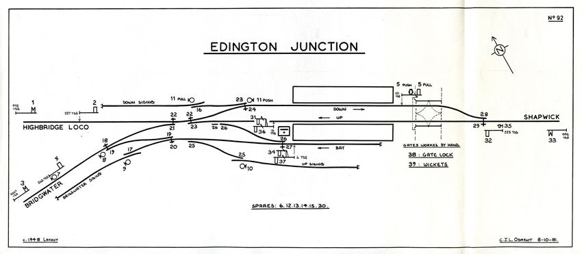
West Country Railway Archives

worked the Down Branch Home, also operated the facing point lock (FPL) on points
14, whilst a similar arrangement existed with lever 32 and points 22. The relevant
levers would have been painted half red and half blue, to denote their dual function,
and this can be confirmed by a close examination of the above-mentioned interior
photograph. The Bridgwater Railway opened to traffic on 21-July-1890 without a
further inspection of the revised signalling.

At an unknown date (possibly circa-1915) the Dutton frame was replaced by a 39-
lever frame of the Stevens pattern with levers at 4.1/8" centres. At some stage also a
'calling-on' arm was provided under the Up Home (signal 32), as S&DJR Signal
Instruction 238 refers to the removal of this subsidiary arm on 1-May-1913 (along
with the Down Advanced Starting signal), but it is not known if this alteration took
place before or after the replacement of the lever-frame. The 1930 signal diagram is
taken from a copy stamped 16-June-1930; the original negative date is 3-July-1915,
which may relate to the renewal of the lever-frame.

One unusual feature of this layout (which is not obvious without an examination of
the mechanical locking table) was that the Up Distant (signal 33) - although only a
single arm - could be worked for either the 'Highbridge' or the 'Bridgwater' routes. It
will be noted also that there were several FPLs on various trailing and trap points;
the reason for these is uncertain, but they may have been provided to permit the
shunting of loaded through carriages or the reversing of through trains between
Bridgwater and Highbridge. The FPL on 25 is a puzzle, as the locking-table
describes 20 merely as "FPL on 19 east end", whereas on the actual diagram the
plunger is labelled as "locks 25 normal or reverse and 19 reverse only".

Subsequently on 13-November-1930 (S&DJR Signal Instruction 308) the Up Home
32 was moved out to 223 yards and disc 35 relocated next to it. Further changes to
the installation are reflected in the 1948 signal diagram below (taken from a BR copy
stamped 6-February-1948), which omits the FPLs on 16 and 25. By September 1949
the FPL 24 had been removed, a track-circuit 'A' provided through points 21 and 23,
and disc 11PUSH relocated in the 'six foot' between the loop lines. By this time FPL
20 was labelled on the diagram merely as 'locks 19 reverse only', yet the locking-
table still showed it as locking 25 both ways.

© CJL Osment V2.1                         3                                 10 March 2021
West Country Railway Archives

The precise situation after the cessation of passenger traffic on the Bridgwater line
on 1-December-1952 is unclear, but it appears that arrangements at Edington
Junction continued relatively unaltered except for the eventual re-naming of the
station as 'Edington Burtle'. (It is assumed that the signal-box was renamed at the
same time, as the new name was used in a subsequent closure notice in 1956.)
Final closure (for goods traffic) of the Bridgwater line took place on 4-October-1954
and the branch was removed in due course. It is not known what further changes (if
any) may have taken place then to the signalling and/or access to the sidings.

In 1956 the signal-box at Edington Burtle was closed, all the track was removed
except for a single running-line (using the former Up Loop) and the siding next to the
Bay, and all the signals except the Up and Down Main Distants, which were retained
to protect the level-crossing. Two new ground-frames (GF) were provided,
designated 'A' and 'B'. GF 'A' was a 2-lever frame located on the Up side adjacent to
the new connection from the main line into the remaining siding; it worked the FPL,
point and trap-point, and was unlocked by the single-line token for the new Shapwick
– Highbridge East 'C' section (see below). GF 'B' was a 3-lever frame located on the
up side adjacent to the level-crossing and it worked the two Distant signals and the
gate bolt; two electric signal arm repeaters were provided in an adjacent cabinet.

There may be some uncertainty about the precise date for these alterations. The
closure date for the signal-box is usually quoted as 4-February-1956, but an official
notice found attached to a copy of the signal-box diagram has been annotated (by
person unknown) that the alterations were carried out on 22-July-1956. As the
original date and source of that notice is unknown, then it is possible that some
confusion has arisen between the work and notice publication dates, so all that can
be stated with certainty therefore is that the changes took place during 1956.

© CJL Osment V2.1                         4                                10 March 2021
West Country Railway Archives

Block Working

By the mid-1870s the S&DJR was being worked on the Absolute Block system by
the use of block instruments only, without any form of physical 'train staff'. S&DJR
Officers Minutes No 376 dated 8-November-1876 records a decision to provide a
box at Edington for the 'telegraph instruments', while Minute 377 states that block
instruments were to be removed from Bason Bridge and “the block made through
from Highbridge to Edington”. Those Minutes would seem to indicate that Edington
station was already a block-post at that time.

Subsequently the S&DJR Working Timetable (WTT) Appendix No 7 (dated 1-March-
1886) states:

                        "BLOCK TELEGRAPH WORKING
               AT MIDFORD, MASBURY, HENSTRIDGE AND EDINGTON”

        These stations, after having accepted the 'Is Line Clear' or 'Train Entering
        Section' signals for an Up or Down train, as the case may be, must not accept
        any signal whatever for a train to come in the opposite direction, unless the
        signals first given have been cancelled in accordance with clause 9 of the
        Block Telegraph Regulations."

However the same Appendix, when dealing with the opening/closing of block-posts
fitted with a block-switch, does not list Edington whereas the other boxes mentioned
above (which were also without passing-loops) are listed, so it is unclear whether
Edington could switch-out. However by late-1886 the 'Train Staff and Ticket' (TS&T)
method of block working had been introduced on the S&DJR line from Evercreech
Junction to Highbridge, after which Edington ceased to be a block-post and became
just an intermediate location within the SHAPWICK - HIGHBRIDGE LOCO block
section.

When the new signal-box was opened at Edington Junction in 1890 the existing
block section was split into two new sections, SHAPWICK – EDINGTON JUNCTION
and EDINGTON JUNCTION - HIGHBRIDGE LOCO, both of which continued to be
worked by TS&T. However the new Bridgwater branch itself was worked by Electric
Train Tablet (ETT) from its opening as a single section EDINGTON JUNCTION –
BRIDGWATER. Tyer's No 3 pattern ETT instruments were used and this was the
first installation of that type on the S&DJR; the tablets were 'A' configuration, with a
round hole in the centre and a semi-circular notch in the edge.

TS&T working at Edington Junction on the section to Shapwick was replaced by ETT
(using Tyer's No 3 instruments) on 8-September-1891 (S&DJR Officers Minutes No
4008 dated 27-October-1891 and Traffic Superintendent's Circulars W/527 and
W/531). A year later (S&DJR Officers Minutes No 4138 dated 27-October-1892) the
S&DJR decided to install ETT working on the section to Highbridge and an
undertaking for this was given to the Board of Trade on 28-January-1893, but the
actual date of introduction is unknown. The Edington Junction – Highbridge Loco
section was equipped initially with Tyer's No 1 instruments (recovered from the

© CJL Osment V2.1                            5                                   10 March 2021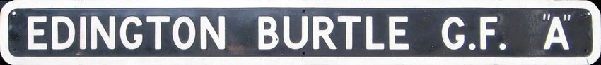
West Country Railway Archives
doubling of the S&DJR main line between Binegar and Shepton Mallet), but these
were replaced by Tyer's No 6 pattern sometime between 1933 and 1939.
In 1950 British Railways (Western Region) took control of the S&DJR lines north and
west of Evercreech Junction, and in due course the ETT working on the Evercreech
Junction to Highbridge line was replaced by the BR(WR) pattern of Electric Key
Token (EKT). It is known that the various sections between Evercreech Junction
North and Glastonbury were converted on 6-April-1952, but no official dates are
known for the alterations between Glastonbury and Highbridge Loco (which would
have included Edington Junction), although it is a reasonable assumption that it was
done circa-1952/53. It is not known therefore whether EKT working was introduced
at Edington Junction before or after that signal-box was renamed Edington Burtle.
Although there are no known formal records relating to the block working on the
Bridgwater branch after closure to passengers in 1952, research information
suggests that the line retained the use of Tyer's No 3 ETT until eventual closure to
goods in 1954. After closure of the former Edington Junction signal-box in 1956 the
block section reverted to SHAPWICK – HIGHBRIDGE EAST 'C' (the former
'Highbridge Loco' box), using 'D' configuration EKT (which also served to unlock the
new Edington Burtle GF 'A').
Cossington
For historical reasons, just like the line from Evercreech Junction to Highbridge, the
branch to Bridgwater unusually was UP to the terminus. Going up the line from
Edington Junction the next signalling installation could be found at Boards Siding,
which was situated on the up side at 2m 18c with a connection facing to Up trains.
This siding is believed to have been opened in 1899 7 and closed in the late 1930s,
being removed by about 1940. The installation consisted of a 3-lever GF (released
by the single-line tablet) which controlled the FPL, points, a bolt on a gate across the
siding, and shunt signals for movements into/out of the siding. The WTT instructions
for Edington Junction stated that this siding should be shunted by a propelling
movement from the junction, to which the train had to return; sadly they did not
indicate what had to be done thereafter with the tablet, which could not be returned
to the ETT instrument at Edington Junction as the No 3 pattern was 'non-returnable'.
The first station on the branch was at Cossington, where the layout underwent a
number of changes over the years and the signalling was modified accordingly. The
original layout consisted of a platform on the up side of the single-line and a single
siding, which was accessed by a connection facing to Down trains at the Bridgwater
end of the platform. Dutton supplied an 8-lever frame located 'back to track' in a hut
on the platform, but the type of frame is unknown.
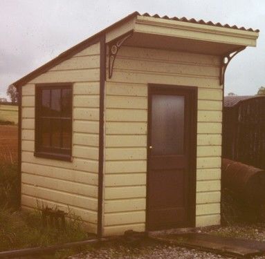
The GF hut at Cossington was similar to one that appears as a
'standard ground-frame hut' in Dutton's catalogue. It is one of
the few S&DJR signalling buildings to have survived and it can
be seen now (without its original lever-frame) as 'Cranmore
West GF' on the East Somerset Railway. The picture shows it
in its new location in 1988/9.
7
Clinker records 2-January-1899 from S&DJR Signalling Instruction 110.
© CJL Osment V2.1 6 10 March 2021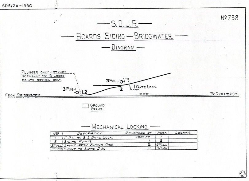
West Country Railway Archives

The layout at Cossington was modified in 1896 when the existing points were moved
southwards to provide space for an additional crossover into the siding facing to Up
trains, thus enabling the siding to be shunted by trains in either direction. The signal
diagram below shows the revised layout and is derived from PRO file MT6/760/10. It
will be noted that the GF is now 10 levers, but it is not known if this indicates a
replacement frame, or merely an extension of the original. There is a note on an old
drawing which implies that levers 1 and 10 were separate 1-lever frames added at
each end of the original frame, but the situation is unclear.

Cossington was never a block-post, just an intermediate GF within the Edington
Junction – Bridgwater block section. Although the signals could be worked for the
passage of trains at any time, the points for the sidings could not be unlocked
without the single-line tablet. At an unknown date the main running signals were
removed and in June 1933 the northern crossover also, leaving a simplified
installation which comprised merely a FPL, the remaining crossover and two ground-
signals, as shown in the diagram below circa-1949.

© CJL Osment V2.1                          7                                 10 March 2021
West Country Railway Archives

It is not known whether the GF remained in use until final closure of the branch to all
traffic on 4-October-1954, or whether it was taken out of use after cessation of
passenger services on 1-December-1952 and the points converted to operation by
local hand-levers. Given the apparent retention of ETT working on the branch until
1954, then it is assumed that the GF would have remained in use.

Bawdrip

The next station on the branch was Bawdrip Halt, which was opened in October
1923 as a simple halt without any signalling, the platform being on the up side of the
line. A small shelter was provided on the platform in 1924.

Bridgwater

Just to the north of Bridgwater station there was another siding also known as
'Boards Siding' (originally 'Wilds' or 'Spinx'), situated on the Down side of the line at
6m 61c with a connection facing to Down trains. This was controlled by a 3-lever GF
(released by the tablet) and a signal diagram is shown below. The arrangement is
identical to that at the other 'Boards Siding' mentioned above, and indeed it seems
that this type of installation was used by the S&DJR at several locations.

Information about the original signalling at Bridgwater is scarce, but it is known from
engineering drawings and OS maps that there was a signal-box on the up (east) side
of the line about mid-way between the level-crossing and the station platform. There
are no known photographs of that signal-box, but one may speculate that it was a
Dutton Type 1 similar to (but probably smaller than) the one provided at Edington
Junction. It is recorded that Dutton supplied a 13-lever frame (11 working and 2
spare levers) and again one can speculate that this would have been of the same
pattern (1889 patent) as fitted at Edington Junction.

© CJL Osment V2.1                          8                                  10 March 2021
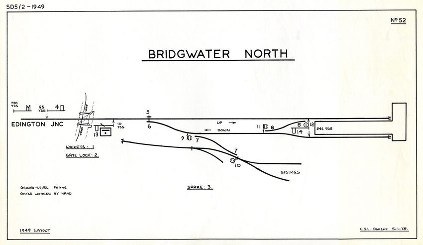
West Country Railway Archives

At an unknown date (believed to have been about 1910 but possibly earlier 8) the
original signal-box was closed and replaced by another box situated on the down
side of the line at 6m 72c next to the level-crossing. There is photographic evidence
that this was a ground-level structure similar to a Dutton Type 1 box (again with the
addition of gable ventilators), which suggests the probability that it was constructed
by re-using the top of the original signal-box. This box was equipped with a 14-lever
frame of the 'knee' pattern normally used by the L&SWR in ground-level boxes, with
levers at 4.5/8" centres.

[Note: In the absence of any known relevant records, it is a matter of speculation
why the original signal-box was replaced, whether it had been a ground-level or
elevated structure, and why it was relocated further away from the station. It is also
speculation whether the 'knee' frame was provided concurrent with the second box
or at a later date. However it is considered to be a reasonable 'working assumption'
that the first box was an elevated structure with a Dutton 1889 patent lever-frame,
the relocation may have eliminated the need for a separate crossing-keeper in
addition to the signalman, and the 'knee' frame was supplied for the 'new' box.]

Bridgwater signal-box was renamed Bridgwater North on 26-September-1949 and
the signal diagram shows the installation at the second signal-box at about that date.
(In view of the early practice of working the distant signal at a terminal station it is
possible that the spare lever 3 was originally the distant lever, but without a firm date
for the installation of the lever-frame this must remain merely a theory.) The layout
was unusual in that one platform was signalled for arrivals only, and the other for
departures only, which meant that arriving passenger trains had to be shunted
across to the other platform before leaving again.

8
 RA Lacy in Somerset & Dorset Railway Trust Bulletin Issue 43 quotes 7-September-1903 but his source is
unknown.

© CJL Osment V2.1                                    9                                         10 March 2021
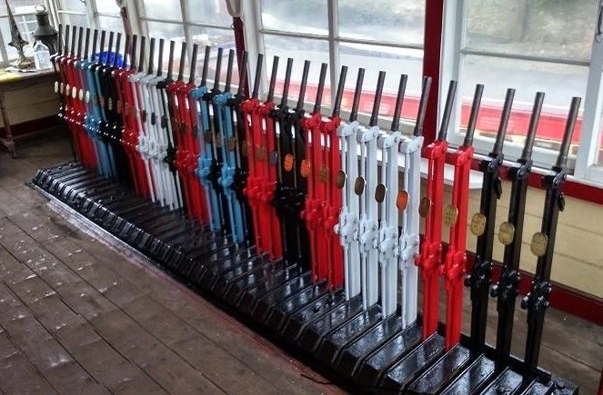
West Country Railway Archives

Passenger services on the Bridgwater Branch ceased on 1-December-1952. It would
appear that the signal-box remained in use as a block-post and continued to use the
Tyer's No 3 ETT instrument during the subsequent period of goods-only operation.
However it is not known what alterations, if any, were made to the actual signalling at
Bridgwater North. One of the sidings in the goods yard used to extend westwards to
a wharf on the River Parrett, although the final section was removed in 1942. This
wharf line passed close to a similar line which ran from the former GWR station to
Bridgwater Docks, although there had been no connection between the GWR and
S&DJR lines until a new chord was brought into use on 27-June-1954. Then on 4-
October-1954 the entire branch was closed north of 6m 54c, with all the goods traffic
then using the new connection, and the signal-box was closed on the same date.
After cessation of traffic for Boards Siding the remains of the branch were cut back
further to 6m 71c circa-1964, and final closure of the remains of the station and
goods yard came in April 1967.

Dutton 1889 patent lever-frame

Some time prior to 1890 an engineer called William Buck had joined the Dutton firm
and in due course he designed a new pattern of interlocking lever-frame, which was
registered in the Dutton name as Patent 11741 of 1889. This frame had a number of
novel features, the most obvious being that the mechanism which held the levers in
the normal or reverse positions was underneath the operating floor level, rather than
the usual 'catch' resting in a slot in the quadrant plates above the floor. Instead of the
usual small 'catch handle' at the top of the main lever to operate the catch, the main
lever itself was pivoted at the top and connected to the 'catch rod' which ran down
the front of the lever. The action of the signalman pulling/pushing the lever
automatically unlocked/locked the catch mechanism. About 10 lever-frames of this
pattern are known (of which the best-known is that still extant at Douglas on the Isle
of Man) and Buck himself records in his memoirs that production ceased after a total
of about 400 levers. The picture below shows the preserved 36-lever frame at
Douglas after a repaint in 2015.

© CJL Osment V2.1                          10                                  10 March 2021
West Country Railway Archives

Conclusion

The involvement of Duttons with the original signalling of the line gives the
Bridgwater Branch a unique place in S&DJR signalling history and it is unfortunate
that so little definite information is available. The line played a further important role
at the beginning of the 20 th Century, when it was used by Alfred Whitaker (the
S&DJR locomotive superintendent) for trials of his newly-invented mechanism for the
automatic exchanging of single-line tablets at speed. Ironically, once those trials
were completed the exchange apparatus was removed from the branch, and
thereafter used only on the S&DJR 'main line' from Bath to Broadstone!

These notes are based on material produced by the author for the Centenary of the
Bridgwater Railway in 1990, now revised and updated to include additional
information which has come to light subsequently from various sources. The author
would like to thank to fellow Signalling Record Society member Stuart Johnson for
permission to draw heavily upon his own notes and to reproduce the drawing from
his article in SRS Newsletter 101.

© CJL Osment (SRS Corresponding Member for S&DJR Signalling)

Edington Junction 1890 diagram courtesy of Stuart Johnson, Douglas lever-frame photograph
courtesy of Peter Jordan.

References
PRO files: MT6/525/5, MT6/697/6, MT6/760/10, MT6/882/4
S&DJR Officers Minutes: 376&377 (8-Nov-1876), 4008 (27-Oct-1891), 4138 (27-Oct-1892)
S&DJR Signal Instructions: 44, 110, 238, 308
S&DJR Traffic Superintendent's Circulars: W/527, W/531
S&DJR WTT Appendices: No 7 (1886), No 9 (1889), 1905
S&DRT Archives
S&DRT Bulletins: 43, 57, 97, 98, 99, 134
SRS Archives
SRS Newsletter 101
"The Bridgwater Branch" - JD Harrison, pub Oakwood Press 1990
"An Historical Survey of the Somerset & Dorset Railway" – CW Judge & CR Potts,
                                                          pub OPC 1979
"The Signal Box" - Signalling Study Group, pub OPC 1986
"The Somerset & Dorset Railway" - R Atthill, pub David & Charles 2nd ed 1985
"Track Layout Diagrams of the GWR & BR(WR) - Section 18" RA Cooke 2nd ed 1980

© CJL Osment V2.1                          11                                  10 March 2021
You can also read