Behaviour of Various Support Systems for Deep Excavations, Changi Airport Underground MRT Station
←
→
Page content transcription
If your browser does not render page correctly, please read the page content below
RTS Conference, Singapore, 2003

Behaviour of Various Support Systems for Deep
Excavations, Changi Airport Underground MRT Station
C. Murugamoorthy
Land Transport Authority, Singapore

C.M. Kho, B.G. Vaidya & S.K. Tang
CPG Consultants Pte Ltd, Singapore

T. Subramanian
L&M Geotechnic Pte Ltd, Singapore

ABSTRACT: For any deep excavation, it is important that the deformation of its ground support sys-
tem is controlled to minimise the impact on ground movements, and its subsequent effect on the adja-
cent structures. This paper presents the actual behavior of various ground support systems that were
utlilised at the Changi Airport MRT Station construction, and makes comparison of the deformations
relating to their method of construction. These include top-down and bottom-up constructions with
diaphragm walls, soldier piles, sheet pile walls and timber lagging support systems. This paper also
provides the original and back analyses carried out and the typical design parameters derived there-
from.

1 INTRODUCTION

Deep excavation works are becoming very common and unavoidable in many medium to large infra-
structure and building developments. This is especially so in land scarce and highly buildup Singa-
pore. Many of these excavation works are carried out near to existing structures. It is therefore critical
for engineers to be able to assess the inevitable ground movements caused by the excavation and con-
sider its effect on nearby existing structures.

The Changi Airport MRT Station is a major and prestigious project successfully implemented and
completed by the Land Transport Authority of Singapore in year 2002. For the construction of this
large underground station, different methods of deep excavations using various ground support sys-
tems were adopted. This paper presents in some details the results of data collected from instruments
that were installed to measure the ground movements and changes in groundwater pressures due to the
excavations. The behavior of the various ground support systems is compared and discussed briefly.
Results of the original and back analyses done for the respective excavations are also presented and
the typical soil parameters assumed in the analyses are provided.

2 PROJECT DESCRIPTION

The Changi Airport Station is located at the eastern end of Singapore and was constructed as a part of
the completed Changi Airport Line Project to serve as a convenient means of transport for the high
volume of commuters traveling to and from the airport. Figure 1 shows the location map. The Changi
Airport Line is an extension of the existing East-West Line, which begins from Tanah Merah Station
and terminates at Changi Airport Station. The total length of the extension is approximately 6 km.

The Changi Airport Station is located at about 20 m underground beneath the existing Airport Boule-
vard and fully integrated with the existing Airport Terminal 2 and the future Terminal 3. The con-
struction of this large station included the Crossover Tunnels, Station Box, Terminal Atria and Over-
run Tunnels. As part of the continuing development of the airport, the project also included, among
other infrastructures, a new baggage tunnel which runs under the station.
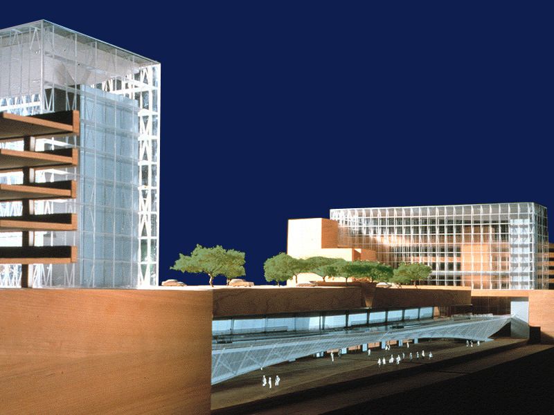
Figure 1. Location Map of Changi Airport Line.
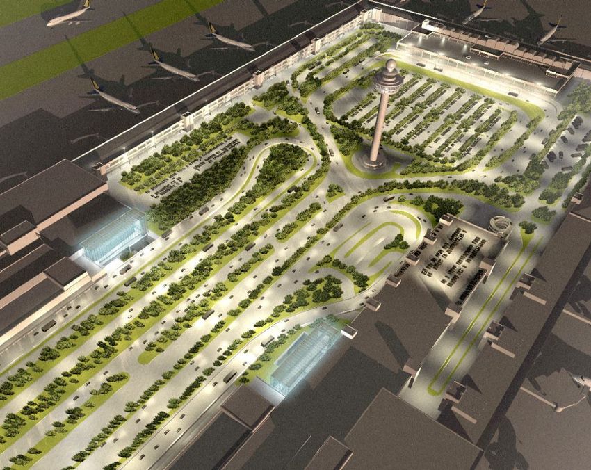
(a) Layout Plan
(b) Perspective Views
Figure 2. Layout Plan of Changi Airport Station.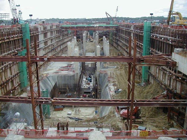
The Crossover Tunnels commence after the end of the eastbound and westbound bored tunnels from
the Expo Station, and are located under the existing airplane parking apron. They consist of a pair of
4.75 m wide by 4.6 m deep cut-and-cover box tunnels, and are about 30 m apart. These twin tunnels
are about 220 m long, and incorporate a crossover before entering the Station Box. The Station Box is
located under the existing Airport Boulevard, and is one of the most spacious stations on the MRT
System at about 35 m wide by 205 m long. At both ends of the Station Box, large Terminal Atria pro-
vide connection and integration with the Airport Terminals. These atrium structures rise from the
basements to reach a height of about 28 m from the ground and are the only visible landmark struc-
tures of the station above ground. Each atrium is about 20 m wide by 60 m long. The Overrun Tunnels
exit from the Station Box and again consists of a pair of parallel 4.75 m wide by 4.6 m deep cut-and-
cover box tunnels, separated by about 30 m. These twin tunnels are about 135 m long and run under-
neath the north end of the existing Terminal 2 buildings. The tunnels clashed with the existing piled
foundations of these buildings. The buildings had to be underpinned, and the affected piles removed,
before the tunnels could be excavated and constructed. A new 4.75 m wide by about 5 m deep bag-
gage tunnel begins between and below the pair of tunnels at the Crossover and continues under the
center of the Station Box before making a turn to run under the eastbound tunnel at the Overrun. Fig-
ures 2a, b show the layout plan and perspective views of the Changi Airport Station respectively.

3 SITE GEOLOGY

From the site investigation conducted, it was found that the site is underlain by Old Alluvium, a soil
stratum formed in the Pleistocene period (10 thousand to 1 million years ago). The Old Alluvium is
massive and slightly to moderately weathered. The soils consist mainly of cemented silty sand, clayey
silt or silty clay with low permeability. It was observed that the cementation often disintegrates after a
few days upon exposure to the environment or when the material comes into contact with free water
(LTA, 1997). The SPT N values obtained in the Old Alluvium are generally higher than 50 and in
some cases exceed 100. The unconfined compressive strength ranges from about 0.5 MPa to 1.5 MPa
and the elastic modulus ranges from about 100 MPa to 200 MPa (KSJV, 1999).

The Old Alluvium stratum is overlain by about 7 m to 13 m of Reclamation Fill, consisting mainly of
materials derived from the Old Alluvium. The materials vary from a clayey soil to sandy gravel. The
SPT N values obtained tend to be higher in the upper levels above the groundwater table but are fre-
quently in the range of 4 to 10 below the upper few metres (KSJV, 1999).

4 INSTRUMENTATION AND MONITORING

A comprehensive package of instrumentation and monitoring was implemented during the excavation
and construction of the station, primarily to assess the design assumptions, stability of the works, ef-
fects on groundwater pressures, and effects on adjacent existing buildings. Some of these instruments
(not exhaustive) are listed below (KSJV, 2000):

a)   Water standpipes and vibrating wire piezometers to measure groundwater pressures
b)   Inclinometers to measure lateral ground and wall movements
c)   Settlement markers and leveling points to measure ground settlements
d)   Strain gauges and load cells to measure strut and ground anchor forces
e)   Optical prism targets, electrolevel beams and electronic tilt sensors to measure building move-
     ments

To control the monitoring, 3 alarm levels in progressive severity were set based on the design and
prediction to ensure the safety of the works.

5 DEEP EXCAVATIONS IN OLD ALLUVIUM

For the construction of the Crossover Tunnels, Station Box, Terminal Atria and Overrun Tunnels, dif-
ferent types and mixtures of excavation methods and ground support systems were adopted. These are
described in Sections 5.1 to 5.4. Figure 3 shows the various methods of construction.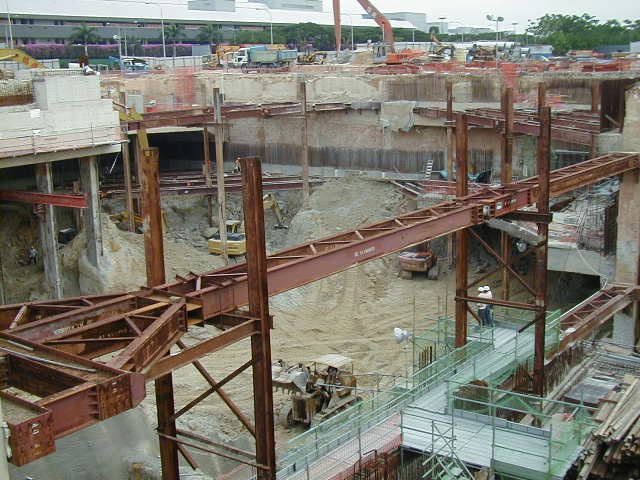
Figure 3. Plan showing Methods of Construction.
5.1 Crossover Tunnels

The Crossover Tunnels were constructed by the cut-and-cover method using a temporary excavation
support system comprising of retaining walls formed by soldier piles with a combination of sheet pile
walls and timber lagging. Sheet pile walls were driven behind the soldier piles above the Old Allu-
vium while timber lagging were installed between the soldier piles below the Old Alluvium to retain
the soil and water. The retaining walls were propped by 5 levels of walers and removable ground anc-
hors. This relatively flexible ground support system was considered adequate because the Crossover
Tunnels are not located near to any existing buildings. Figures 4a, b show the section and a photo-
graph of the excavation at the Crossover Tunnels respectively.

                                                                                                       (b) Photograph of Excavation

                       (a) Section of Excavation

Figure 4. (a) Section (b) Photograph of Excavation at Crossover Tunnels.

                            Lateral Ground Movements (mm)                                                     Piezometric Levels (m)
                  0    10     20   30   40   50    60   70   80   90                              85     90        95      100         105   110
             0                                                                               0
                                                                                                       Sensor Depth
                                                                                                       25 m
             5                                                                               5
                                                                                                       Sensor Depth
                                                                                                       17 m
                                                                       Excavated Depth (m)

             10                                                                              10
 Depth (m)

             15                                                                              15

                                                  Measured

             20                                                                              20
                                                  Original
                                                  Analysis
                                                  Back                                       25
             25
                                                  Analysis

             30                                                                              30

                      (a) Lateral Ground Movements                                                      (b) Piezometric Levels

Figure 5. (a) Lateral Ground Movements (b) Piezometric Levels at Crossover Tunnels.
Figures 5a presents the upper bound of the lateral ground movements measured from 4 inclinometers
installed in boreholes next to the retaining walls. The maximum lateral ground movement measured
was about 87 mm and occurred at around the mid depth of the excavation. It was observed that the
measured lateral ground movements were excessively higher than the predicted values. This was
probably due to unforeseen pockets of Marine Clay that were encountered within the Reclamation Fill
at some areas of the Crossover Tunnels. Figure 5b presents the piezometric levels measured from 18
vibrating wire piezometers installed adjacent to the excavation with the sensors located in the Old Al-
luvium near the formation level. The piezometric levels were lowered to a maximum of about 15 m as
the excavated depth reached the formation level. The groundwater table measured from standpipes
was lowered by about 4 m to 5 m.
5.2 Station Box
The Station Box was constructed by the top-down cut-and-cover method. The excavation support sys-
tem comprised of permanent 1000 mm thick diaphragm walls propped by a permanent concrete top
slab and 2 levels of temporary walers and removable ground anchors. The diaphragm walls form part
of the station walls while the concrete top slab forms the station roof slab. After the installation of the
diaphragm walls, the roof slab was first constructed and the ground backfilled. Further excavation and
construction works were then carried out below the roof slab through temporary openings. This me-
thod of construction was adopted because of site and time constraints. Airport Boulevard, the only
road access to the airport, is located directly above the Station Box. As such, the Station Box had to
be constructed in sections for the necessary diversion of this busy road. In order for the road to be
reinstated back to its original alignment and to release the affected section of the Station Box for con-
struction, the roof slab had to be constructed and ground backfilled as early as possible. Figures 6a, b
show the section and a photograph of the excavation at the Station Box respectively.
Figure 7a presents the upper bound of the lateral ground movements measured from 2 inclinometers
installed in boreholes next to the diaphragm walls and 2 inclinometers installed in the diaphragm
walls. The maximum lateral ground movement measured was about 11 mm and occurred at around the
mid depth of the excavation. Figure 7b presents the piezometric levels measured from 12 vibrating
wire piezometers installed adjacent to the excavation with the sensors located in the Old Alluvium
near the formation level. The piezometric levels were lowered to a maximum of about 12 m as the ex-
cavated depth reached the formation level. The groundwater table measured from standpipes generally
remained perched just below the ground level.
(b) Photograph of Excavation
(a) Section of Excavation
Figure 6. (a) Section (b) Photograph of Excavation at Station Box.Lateral Ground Movements (mm) Piezometric Levels (m)
0 5 10 15 85 90 95 100 105 110
0 0
Sensor Depth
5 5 27 m
Sensor Depth
Measured 20 m
Excavated Depth (m)
10 10
Original
Depth (m)
Analysis
15 Back 15
Analysis
20 20
25 25
30 30
(a) Lateral Ground Movements (b) Piezometric Levels
Figure 7. (a) Lateral Ground Movements (b) Piezometric Levels at Station Box.
5.3 Terminal 3 Atrium
The Terminal 3 Atrium is built within a large open box structure at the west end of the Station Box.
This open box structure was constructed by the bottom-up method. The excavation support system
comprised of permanent 1000 mm thick diaphragm walls propped by 2 levels of temporary walers and
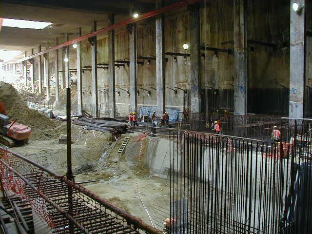
corner struts. Figures 8a, b show the section and a photograph of the excavation at the Terminal 3
Atrium respectively.
(b) Photograph of Excavation
(a) Section of Excavation
Figure 8. (a) Section (b) Photograph of Excavation at Terminal 3 Atrium.Lateral Ground Movements (mm) Piezometric Levels (m)
0 5 10 15 20 95 100 105
0 0
5 5
10 10
Excavated Depth (m)
Depth (m)
15 15
20 20
Measured
25 25 Sensor Depth
Original 26 m
Analysis
Sensor Depth
30 Back 30 19 m
Analysis
35 35
(a) Lateral Ground Movements (b) Piezometric Levels
Figure 9. (a) Lateral Ground Movements (b) Piezometric Levels at Terminal 3 Atrium.
Figure 9a presents the upper bound of the lateral ground movements measured from 1 inclinometer
installed in a borehole next to the diaphragm wall and 2 inclinometers installed in the diaphragm
walls. The maximum lateral ground movement measured was about 17 mm and occurred near the top
of the excavation. Figure 9b presents the piezometric levels measured from 4 vibrating wire piezome-
ters installed adjacent to the excavation with the sensors located in the Old Alluvium near the forma-
tion level. The piezometric levels were lowered to a maximum of about 7 m as the excavated depth
reached the formation level. The groundwater table measured from standpipes generally remained
perched just below the ground level.
5.4 Eastbound Overrun Tunnel
The Eastbound Overrun Tunnel was constructed in a narrow excavation by the bottom-up cut-and-
cover method. The tunnel consists of a double cell stacked box with the baggage tunnel at the bottom.
The excavation support system comprised of 800 mm thick diaphragm walls propped by 2 levels of
temporary walers and struts, a permanent top slab and a permanent intermediate slab. As the Overrun
Tunnels pass underneath part of the existing Terminal 2 buildings (Car Park B, Basement Bus Ramp,
Sky Train People Mover System and North Finger Pier) and clashed with their piled foundations,
these buildings had to be underpinned and the affected foundations removed first before the construc-
tion of the tunnels could take place. The affected columns of the buildings were underpinned using
the diaphragm walls, which form the new permanent foundations. Figure 10 shows the section of the
excavation at the Eastbound Overrun Tunnel.
Figure 11a presents the upper bound of the lateral ground movements measured from 2 inclinometers
installed in boreholes next to the diaphragm walls and 4 inclinometers installed in the diaphragm
walls. The maximum lateral ground movement measured was about 9 mm and occurred near the bot-
tom of the excavation. Figure 11b presents the piezometric levels measured from 6 vibrating wire pie-
zometers installed adjacent to the excavation with the sensors located in the Old Alluvium near the
formation level. The piezometric levels were lowered to a maximum of about 14 m as the excavated
depth reached the formation level. The groundwater table measured from standpipes generally re-
mained perched just below the ground level.Figure 10. Section of Excavation at Eastbound Overrun Tunnel.
Lateral Ground Movements (mm) Piezometric Levels (m)
0 5 10 15 85 90 95 100 105
0 0
Measured
Sensor Depth
5 5 28 m
Original
Analysis Sensor Depth
22 m
10 Back 10
Excavated Depth (m)
Analysis
15
Depth (m)
15
20 20
25 25
30 30
35 35
(a) Lateral Ground Movements (b) Piezometric Levels
Figure 11. (a) Lateral Ground Movements (b) Piezometric Levels at Eastbound Overrun Tunnel.
6 EXCAVATION BACK ANALYSES
Original and back analyses of the excavations were carried out using WALLAP for all the case stu-
dies presented. Undrained soil strength and modulus parameters for the Old Alluvium using Mohr-
Coulomb Elastic-Perfectly Plastic constitutive soil model were assumed. Table 2 summarizes the soil
parameters used in the analyses.Table 2. Summary of Soil Parameters.
Undrained Shear Strength Elastic Modulus
Unit Friction
(kPa) (MPa)
Soil Weight Angle
Original Back Anal- Original Back Anal-
(kN/m3) (Degree)
Analysis ysis Analysis ysis
Reclamation Fill 19 30 - - 5 + 1.5z * 10
Old Alluvium above 250 250 150 125
20 -
Formation Level (4 – 5 N) (4 – 5 N) (2.5 – 3 N) (2 – 2.5 N)
Old Alluvium below 250 250 150 300
20 -
Formation Level (4 – 5 N) (4 – 5 N) (2.5 – 3 N) (5 – 6 N)
* z is the depth from the ground level
It should be noted that for the back analyses, a higher soil modulus was assumed for the Old Alluvium
below the formation level. This assumption is considered reasonable, as soil strains were significantly
smaller below the formation level, hence only the small strain modulus was mobilized. The predicted
lateral ground movements from the original and back analyses for the Crossover Tunnels, Station
Box, T3 Atrium and Eastbound Overrun Tunnel are plotted in Figures 5a, 7a, 9a and 11a respectively.
7 OBSERVATIONS & DISCUSSIONS
It is well established that the behavior of excavations and the support systems are affected by various
factors, some of which are listed below:
a) Soil stratification and properties
b) Depth and width of excavation
c) Type of retaining wall
d) Type of propping and preloading
e) Method of construction and workmanship
The case studies presented in this paper have demonstrated the influence of some of these factors. The
relatively uniform soil strata of the site allowed some reasonable comparisons of the various excava-
tions and support systems. Table 3 summarizes and compares the lateral ground movements of the dif-
ferent excavations.
Table 3. Comparison of Maximum Lateral Ground Movements for Different Excavations.
Maximum Lateral
Ground Movement
Construction
Location Structural System Original Back
Method Measured
Analysis Analysis
(mm)
(mm) (mm)
Soldier piles with sheet pile walls
Crossover
Bottom-up & timber lagging propped by 87 53 72
Tunnels
ground anchors
Diaphragm walls propped by
Station Box Top-down 11 11 11
ground anchors
Diaphragm walls propped by
T3 Atrium Bottom-up 17 14 19
struts
Eastbound Diaphragm walls propped by
Bottom-up 9 12 12
Overrun Tunnel struts
7.1 Flexible versus Rigid Retaining Walls
The ground movements of the support system using the flexible soldier piles with sheet pile walls and
timber lagging at the Crossover Tunnels (Figure 5a) were much larger (more than 5 times) than those
for the support system using the stiff diaphragm walls at the Station Box (Figure 7a). This clearly in-
dicates that the stiffness of the retaining walls is a major, if not the most important, factor in control-
ling ground movements.7.2 Top-Down versus Bottom-Up Methods The comparison of ground movement profiles of the Station Box (Figure 7a) and T3 Atrium (Figure 9a) confirms that the top-down method was effective in reducing, if not practically preventing, any ground movements at the top of the excavation. This was obviously due to the very stiff concrete top slab that was constructed against the diaphragm walls before any significant excavation was started. Another major advantage of the top-down method was that it allowed works to be carried out on and above the ground level while the excavation was ongoing. This resulted in substantial timesavings as aboveground activities were undertaken concurrently. However, the top-down method did have its drawbacks. One such shortcoming was that access to the excavation was limited to the size and num- ber of temporary openings provided in the top slab. This restriction resulted in a slower excavation and muck removal rate, and affected the subsequent construction activities. This problem was alle- viated by detailed advanced planning and providing more large openings in the top slab. Waterproof- ing problems were also encountered during the closure of these openings. 7.3 Ground Anchors versus Struts By comparing the magnitude of the ground movements around the mid depth (10 m to 15 m) of the excavation at the Station Box (Figure 7a) and T3 Atrium (Figure 9a), it generally appears that the strutted system at the T3 Atrium performed better in minimizing ground movements when compared to the ground anchored system at the Station Box. This is even after recognizing the fact that the ex- cavation at the T3 Atrium was wider than the excavation at the Station Box. Although this observa- tion is not so obvious due to the different configurations of the excavations, it is still reasonable to remark that a strutted system is normally more rigid than a ground anchored system. Hence, if all oth- er factors remain the same, a strutted system would be more effective in controlling ground move- ments. However, a major disadvantage of the strutted system was that it created significant space con- strains within the excavation, thus hampering the construction works. Waterproofing of the base slab was also more difficult due to the kingpost penetrations. The ground anchored system whereas offered practically no obstruction within the excavation, making it much easier and faster for the construction works to progress. 7.4 Narrow versus Wide Excavations It can be seen that the ground movements of the narrow excavation (width is approximately one third the depth of excavation) at the Eastbound Overrun Tunnel (Figure 11a) were noticeably smaller in magnitude than the ground movements measured at the much wider (width is at least 2 times or more than the depth of excavation) Station Box (Figures 7a) and T3 Atrium (Figures 9a). All of these areas used diaphragm walls as the retaining system, although the walls were less stiff (800 mm thick) at the Eastbound Overrun Tunnel when compared to the walls (1000 mm thick) at the Station Box or T3 Atrium. The smaller ground movements could be attributed to the soil confinement within the excava- tion, which had the effect of increasing the soil stiffness. Another reason could be due to the smaller elastic shortening of the shorter spanning struts. In general, it should be noted that this trend of re- duced ground movement in narrow excavations is only apparent where the width is less than the depth of excavation. When the width of excavation exceeds its depth, this behavior becomes less significant. 7.5 Changes in Groundwater Pressures From all the case studies presented (Figures 5b, 7b, 9b & 11b), it can be seen that the maximum lo- wering of piezometric levels within the Old Alluvium was about 7 m to 15 m. At all the areas other than the Crossover Tunnels, no significant ingress of water through the retaining walls was observed. There was also no significant drawdown of the groundwater table. The substantial drop in piezometric levels in the Old Alluvium was most likely due to stress relieve in the soil during excavation. This was not a real concern as the Old Alluvium was over-consolidated and no significant ground settle- ment was expected to occur as a result.
At the Crossover area, there were some localized ingresses of water through the retaining walls at the
soil interface between the Reclamation Fill and Old Alluvium. This was the main cause of the draw-
down in groundwater table of about 4 m to 5 m at this area. As a result of the drawdown, relatively
large ground settlements of up to 114 mm were observed.

8 CONCLUSION

In this paper, the behaviour of various excavation support systems used for the construction of Changi
Airport Station has been contrasted. Some of the factors affecting the behaviour of excavations were
also identified and discussed. One of the most effective means of reducing ground movements is by
using rigid retaining walls with strutting.

Original and back analyses of the excavations were carried out using WALLAP for the case studies
presented. As a general guide for the preliminary design of excavation support systems in the Old Al-
luvium with similar ranges of SPT N values, it is proposed to adopt an undrained shear strength of
250 kPa (4 – 5 N). An elastic modulus of 125 MPa (2 – 2.5 N) above the formation level and 300 MPa
(5 – 6 N) below the formation level is suggested.

ACKNOWLEDGEMENTS

The authors would first like to acknowledge the Land Transport Authority of Singapore, in particular
the Project Director of the Changi Airport Line Project, Mr P. Sripathy for granting permission for
this paper to be published. The assistance rendered by Ms Rafidah Ithnin in retrieving the necessary
records from the archive is greatly appreciated. Special thanks must also go to Mr Sunny Quek for
preparing some of the figures.

REFERENCES

Kumagai-Sembawang Joint Venture. 1999. Changi Airport Line, Contract 504, Construction of Changi Airport
  Station, Geotechnical Analysis Report (Vol. 1), General Ground Conditions and Design Approach.
Kumagai-Sembawang Joint Venture. 2000. Changi Airport Line, Contract 504, Construction of Changi Airport
  Station, Consolidated Manual for Instrumentation and Monitoring.
Land Transport Authority. 1997. Changi Extension Line Project, Geotechnical Interpretative Report for the
  Changi Extension Line.
You can also read