CRA - 210 ANALOG TELEPHONE ADAPTER - 3 ETHERNET PORT + 2 VOIP LINE + 1 PSTN LINE CRA-210 USER MANUAL GUIDE
←
→
Page content transcription
If your browser does not render page correctly, please read the page content below
CRA-210 User Manual Guide

    CRA – 210
    Analog Telephone Adapter
    3 Ethernet Port + 2 VoIP Line + 1 PSTN Line

    Getting Started Guide

_______________________________________________________________________________
                                                                   Page: 1 of 30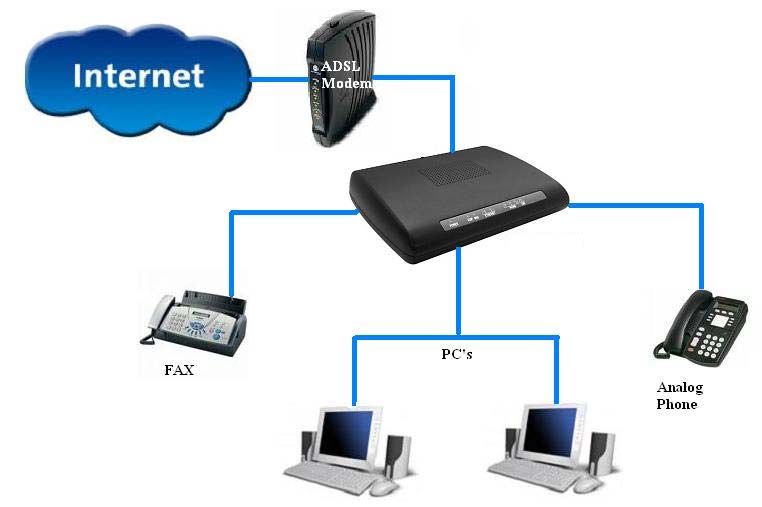
CRA-210 User Manual Guide

                                     Table of Contents

    1. WELCOME - - - - - - - - - - - - - - - - - - - - - - - - - - - - - - - - - - - - - - - - - - - -5

    2. PRODUCT OVERVIEW- - - - - - - - - - - - - - - - - - - - - - - - - - - - - - - - - - - 5
        2.1. Typical setup of CRA-210 - - - - - - - - - - - - - - - - - - - - - - - - - - - - - - -5
        2.2. Back Panel Ports - - - - - - - - - - - - - - - - - - - - - - - - - - - - - - - - - - - - - 6
        2.3. Front Panel Ports - - - - - - - - - - - - - - - - - - - - - - - - - - - - - - - - - - - - - 6
        2.4. Key Features - - - - - - - - - - - - - - - - - - - - - - - - - - - - - - - - - - - - - - - -7
        2.5. Hardware Specifications - - - - - - - - - - - - - - - - - - - - - - - - - - - - - - - - 8

    3. INSTALLATION REQUIREMENTS - - - - - - - - - - - - - - - - - - - - - - - - 9
        3.1. Package Contents - - - - - - - - - - - - - - - - - - - - - - - - - - - - - - - - - - - - 9
        3.2. Other Requirements - - - - - - - - - - - - - - - - - - - - - - - - - - - - - - - - - - -10

    4. CONFIGURATION GUIDE - - - - - - - - - - - - - - - - - - - - - - - - - - - - - - - 10
        4.1. Hardware Installation - - - - - - - - - - - - - - - - - - - - - - - - - - - - - - - - - - 10
        4.2. Configuring CRA-210 through Web Browser - - - - - - - - - - - - - - - - - -11
            4.2.1. To access your ATA Web Panel with simple guidelines - - - - - - - 11

            4.2.2. Login Information - - - - - - - - - - - - - - - - - - - - - - - - - - - - - - - - -13

            4.2.3. Network Configuration - - - - - - - - - - - - - - - - - - - - - - - - - - - - - 14
                4.2.3.1.     LAN Setup - - - - - - - - - - - - - - - - - - - - - - - - - - - - - - - - -14
                4.2.3.2.     WAN Setup - - - - - - - - - - - - - - - - - - - - - - - - - - - - - - - - 15
                4.2.3.3.     Port Forwarding and Firewall - - - - - - - - - - - - - - - - - - - -16
                4.2.3.4.     Advanced Routing - - - - - - - - - - - - - - - - - - - - - - - - - - - -17

            4.2.4. VoIP Configuration - - - - - - - - - - - - - - - - - - - - - - - - - - - - - - - -18
                4.2.4.1.     SIP Configuration - - - - - - - - - - - - - - - - - - - - - - - - - - - - 18

_______________________________________________________________________________
                                                                   Page: 2 of 30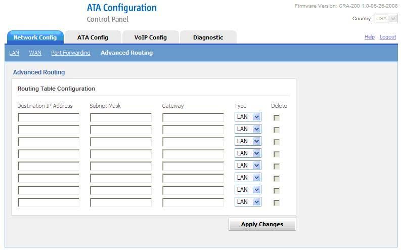
CRA-210 User Manual Guide
               4.2.4.2.     Fax Configuration - - - - - - - - - - - - - - - - - - - - - - - - - - - -19
               4.2.4.3.     Codec Configuration - - - - - - - - - - - - - - - - - - - - - - - - - - 19
               4.2.4.4.     Volume Configuration - - - - - - - - - - - - - - - - - - - - - - - - - 19
               4.2.4.5.     Configuring the PSTN (FXO) Gateway- - - - - - - - - - - - - -20
                   4.2.4.5.1. Connecting to PSTN to VoIP Services - - - - - - - - - - - -20
                   4.2.4.5.2. Connecting to VoIP to PSTN Services- - - - - - - - - - - - 22
                   4.2.4.5.3. Receive a PSTN call from the Phone Port (FXS)directly22
                   4.2.4.5.4. Make a PSTN call from the Phone Port (FXS) directly- 23
                   4.2.4.5.5. Maximum Rings - - - - - - - - - - - - - - - - - - - - - - - - - - -23

               4.2.4.6.     Local Extensions - - - - - - - - - - - - - - - - - - - - - - - - - - - - -24

               4.2.4.7.     ATA’s Advanced Features - - - - - - - - - - - - - - - - - - - - - - 24

           4.2.5. ATA Configuration - - - - - - - - - - - - - - - - - - - - - - - - - - - - - - - -25
               4.2.5.1.     User Administration- - - - - - - - - - - - - - - - - - - - - - - - - - -25
               4.2.5.2.     Password Management - - - - - - - - - - - - - - - - - - - - - - - - -25
               4.2.5.3.     ATA System Reset - - - - - - - - - - - - - - - - - - - - - - - - - - - 26

           4.2.6. Firmware Upgrade - - - - - - - - - - - - - - - - - - - - - - - - - - - - - - - - 27

       4.3. Telephony Features - - - - - - - - - - - - - - - - - - - - - - - - - - - - - - - - - - - 28
           4.3.1. Call Hold - - - - - - - - - - - - - - - - - - - - - - - - - - - - - - - - - - - - - - -28
           4.3.2. Call Waiting - - - - - - - - - - - - - - - - - - - - - - - - - - - - - - - - - - - - 28
           4.3.3. Call Transfer - - - - - - - - - - - - - - - - - - - - - - - - - - - - - - - - - - - - 28
               4.3.3.1.       Attended Call Transfer - - - - - - - - - - - - - - - - - - - - - - - 28
               4.3.3.2.       Unattended Call Transfer - - - - - - - - - - - - - - - - - - - - - -28
           4.3.4. 3-way Conferencing - - - - - - - - - - - - - - - - - - - - - - - - - - - - - - - 29

    5. COMPLIANCE AND SAFETY INFORMATION - - - - - - - - - - - - - - - -29
       5.1. Installation Precautions - - - - - - - - - - - - - - - - - - - - - - - - - - - - - - - - - 29
       5.2. FCC and CE Notice - - - - - - - - - - - - - - - - - - - - - - - - - - - - - - - - - - - 29

_______________________________________________________________________________
                                                                   Page: 3 of 30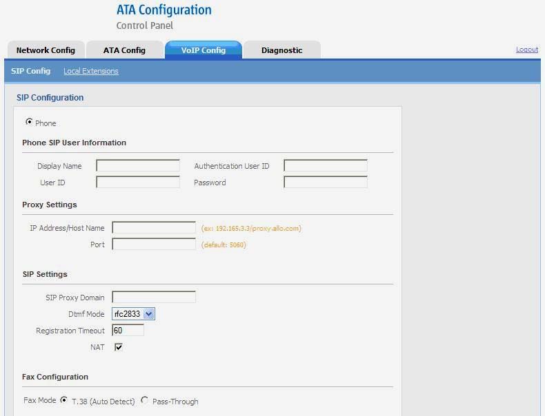
CRA-210 User Manual Guide

_______________________________________________________________________________
                                                                   Page: 4 of 30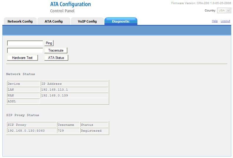
CRA-210 User Manual Guide
    1. WELCOME
       Thank you for choosing the CRA-210 for Voice-over-IP. This Phone Adapter will
       allow you to make phone or fax calls using your broadband connection.

       The CRA-210 offers a rich set of functionality and superb sound quality at ultra-
       affordable price. They are fully compatible with SIP industry standard and can
       interoperate with many other SIP compliant devices and software on the market.

    2. PRODUCT OVERVIEW
       The CRA-210 is an Analog Telephone Adapter that allows customers to connect one
       analog phone to SIP devices. With the Phone Adapter, your phones or fax machines can
       share your high-speed Internet connection and take advantage of it.

       You will be able to make phone calls using the account you set up with ITSP (Internet
       Telephony Service Provider), even while you’re surfing the Internet. It is also perfect
       for connecting home workers to the main office when it is not desirable to use an IP
       phone.

    2.1. Typical setup of CRA-210

                  Figure 2-1: Interconnection Diagram of the CRA-210

_______________________________________________________________________________
                                                                   Page: 5 of 30
CRA-210 User Manual Guide

    2.2. Back Panel Ports
       The Phone Adapter’s ports are located on the back panel.

                                Figure 2-1: Back Panel

       PHONE Port: For your Internet phone line, this port allows you to connect your
       telephone or fax machine to the Phone Adapter using an RJ-11 telephone cable

       ETHERNET Port: The ETHERNET port allows you to connect the Phone Adapter to
       your router or gateway using a Category 5 Ethernet network cable.

       POWER Port: The POWER port is where you will connect the included power
       adapter.

       RESET BUTTON: To restore CRA-210 into factory default settings. It will change
       the configuration back to factory settings, including network settings.

    2.3. The Front Panel
       The Phone Adapter’s LEDs are located on the front panel.

                             Figure 2-2: Front Panel
_______________________________________________________________________________
                                                                   Page: 6 of 30
CRA-210 User Manual Guide
Power LED Green: The Power LED lights up when the Phone Adapter is powered on
and ready.
VoIP LED Green: The VoIP LED lights up only when ATA got registered to any
ITSP SIP account.
ETHERNET LED Green: The ETHERNET LED lights up when the Phone Adapter
is connected to your network through the Ethernet port. It flashes when there is data
being sent or received.
PHONE LED Orange: The PHONE LED is solidly lit when a telephone or fax
machine got registered to any ITSP through Internet connection. (The connection will
get register only if your ITSP account is active). And the PHONE LED changes to
BLUE when the phone is on the hook.
2.4. Key Features
The CRA-210 has the following features.
• Supports SIP V2 (RFC 3261)
• Supports a variety of services such as Caller ID display and generation,
Call transfer, Call waiting, Call holding and 3-way conferencing
• Supports MTU size negotiation,
• Supports Static IP, DHCP Client / Server and PPPoE
• Built-in router, NAT and Gateway
• Supports DHCP IP Reservation, Port Forwarding and Advanced Routing.
• Supports VAD with Silence Suppression, CNG , Echo Cancellation and
Adaptive jitter buffer
• Supports the traditional fax service using T.38 formats
• Supports gain adjustment to FXS ports
• Supports firmware upgrade via HTTP
• Supports Auto-provision
• Support the following codec:
o G.711 A / µ-law
o G.729AB
o G.723
o G.726
_______________________________________________________________________________
Page: 7 of 30CRA-210 User Manual Guide
2.5. Hardware Specifications
The table below lists the hardware specification of CRA-210
Model CRA-210
Three RJ-45 10/100 Mbps Ethernet
One Power Port
Port Two RJ-11 FXS Port
One RJ-11 FXO Port
LED Power & Ethernet (Green)
Phone (Blue & Orange)
Power Adaptor Input: 100-240VAC
Output: +12VDC, 1500mA
Dimension 149 mm (W)
180 mm (L)
45 mm (H)
Weight 0.32 kg
Operating Temp. 10° - 40°C
50° - 104°F
Operating Humidity 10% - 90% (non-condensing)
_______________________________________________________________________________
Page: 8 of 30CRA-210 User Manual Guide
3. INSTALLATION REQUIREMENTS
3.1. Package Contents
Analog Telephone Adapter Unit (CRA-210) Standard Telephone cable (RJ11)
Power Adaptor Ethernet Cable (RJ 45)
Quick Installation Guide
_______________________________________________________________________________
Page: 9 of 30CRA-210 User Manual Guide
3.2. Other Requirements:
• Telephone Unit
• Broadband Internet connection (DSL or Cable Modem)
• A Router (if you have multiple devices using Internet connections)
• An ITSP VoIP Account
4. CONFIGURATION GUIDE
4.1. Hardware Installation
To install the Analog Telephone Adapter (ATA) follow these instructions.
4.1.1. Connect the Ethernet network cable (RJ45) into the WAN port of the ATA
unit, as shown in Figure 4.1: Connect the other end to the one of the
Ethernet ports on your router or gateway.
Figure 4.1
4.1.2. Connect the Standard Telephone Cable (RJ11) into the phone port labeled
PHONE as shown in Figure 4.2. Connect the other end of the cable to your
telephone. You can plug either phone or fax machine.
Figure 4.2
4.1.3. Connect the included power adapter to the POWER port on the back panel
of the Phone Adapter as shown in Figure 4.3. Connect the other end to a
standard electrical outlet, which will power up the ATA unit.
_______________________________________________________________________________
Page: 10 of 30CRA-210 User Manual Guide
Wait until the POWER,
and WAN LED's turn
green and remain stable
on the Front Panel of
your ATA (LAN LED
might also be green).
Figure 4.3
4.2. Configuring CRA-210 through Web Browser
Your ATA Web Panel will allow you to configure and modify the Network Settings,
SIP settings and to upgrade your ATA's Firmware. And it will also allow you to
check the status of SIP your account
4.2.1. To access your ATA Web Panel, follow these simple guidelines:
STEP 1: First, connect the ATA’s LAN port to your PC network card and then
disable & enable the Local Area Connection available in the Control
Panel -> Network Connections. The ATA will release the IP address in
the series of 192.168.113.X. And then launch the web browser on
the PC. Enter http://192.168.113.1 in the Address field
(192.168.113.1 is the default local IP address of the ATA). Then press
the Enter key.
STEP 2: Or you can login to the ATA through the WAN IP address if both
ATA and PC are connected to the same network (which is connected to
the DHCP server), then you can get the IP address of the ATA through
the phone connected to ATA by dialing “ * * ”. Then it will announce
the current WAN IP Address, which is released by the DHCP server.
Then enter WAN IP address in the web browser address field to get
Login Screen. To access the CRA-210’s Web configuration Menu use
the following URL:
http:// CRA-210 -IP-Address
where the CRA-210-IP-Address is the IP address of the CRA-210.
_______________________________________________________________________________
Page: 11 of 30CRA-210 User Manual Guide
STEP 3: Once this request is entered and sent from a Web browser, the ATA
will respond with the login screen as shown in Figure4.4.
Figure4.4
STEP 4: Use the Login Information which is specified in the 4.2.2 to login
to the ATA.
Status Page
After Logged In, you can see Network Status and SIP Proxy Status in the Status Page as
shown in Figure 4.5
Figure 4.5
_______________________________________________________________________________
Page: 12 of 30CRA-210 User Manual Guide
Status Page
Ping It is used to check the packet loss and latency time from your ATA to
check the quality of your network connection.
Traceroute It is used to determine the route taken by packets across an IP network.
Hardware Test It contains a suite of diagnostics that will test the hardware of your ATA
It provides detailed information about SIP Proxy Status, SIP Phone
Status, System Uptime, LAN & WAN configuration, Ethernet Status
ATA Status
and SIP Configuration (Phone).
Network Status This shows LAN, WAN and ADSL IP Address.
SIP Proxy This shows whether the unit is registered to VoIP service provider’s
Status server.
4.2.2. Login Information
CRA-210 has two level of management: Administrator Level and Normal User Level.
The factory default Login Information for User and administrator is mentioned below.
Administrator Level Normal User Level
User Name: admin User Name: cem123
Password: admin Password: cem123
User Type: Admin User Type: Normal User
Administrator level has higher access privilege, and is allowed to create and change
password for all users. User Level has lower access privilege and certain options are
not available including SIP account settings.
The CRA-210 allows multiple users to log on at the same time i.e. both
Administrator & Normal User. After a user logs on, user will be automatically logged
off if there is no activity for 10 min.
_______________________________________________________________________________
Page: 13 of 30CRA-210 User Manual Guide
4.2.3. Network Configuration
4.2.3.1. LAN Setup
Figure 4.6
The table below lists the LAN Setup of CRA-210
LAN Setup
LAN Static IP Configuration
IP Address It is a Base IP Address of a LAN Port, which functions as a
gateway for its LAN. Default value is 192.168.113.1
Subnet Mask Sets the LAN subnet mask. Default value is 255.255.255.0.
DHCP Server Configuration
Enable DHCP Server This option allows you to enable the DHCP Server on LAN
port.
_______________________________________________________________________________
Page: 14 of 30CRA-210 User Manual Guide
Starting IP Address Starting IP address in the DHCP Scope
Ending IP Address Ending IP address in the DHCP Scope
DHCP Lease Time The amount of time that a given IP address will be valid
for a LAN client. Default value is 24hr(86400 seconds)
DHCP IP Reservation
IP Address Allows you to assign a specific IP address to a specific
computer without any configuration on the client.
MAC Address MAC address of the PC which you want to bind the
specific IP address.
Delete Used to delete the configured IP to MAC bindings.
4.2.3.2. WAN Setup
Figure 4.7
_______________________________________________________________________________
Page: 15 of 30CRA-210 User Manual Guide
The table below lists the WAN Setup of CRA-210
WAN Setup
WAN Configuration
Automatic configuration It automatically takes IP addresses and other network
via DHCP Server configuration information (subnet mask, broadcast address,
etc) from DHCP Server
Using ISP Account (PPPoE)
It is a PPPoE username. Fill this field if your ISP requires you
User Name to use a PPPoE connection.
Password PPPoE account password.
Enable Keep Alive Timer Enable to keeps your Internet connection alive.
If Static IP mode is selected, then assign the IP address, Subnet
Using Static IP Mask, Default Router IP address, Primary DNS, Secondary
DNS fields.
MAC Address Clone Allow user to set a specific MAC address. Set in Hex format.
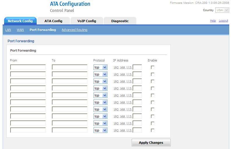
4.2.3.3. Port Forwarding and Firewall
Figure 4.8
_______________________________________________________________________________
Page: 16 of 30CRA-210 User Manual Guide
Figure 4.9
Port Forwarding and Firewall
Allow user to forward a matching (TCP/UDP) port to a
Port Forwarding specific LAN IP address with a specific (TCP/UDP) port.
If it is Enabled, it will protect the resources of a private
Firewall network from users from other networks.
4.2.3.4. Advanced Routing
Figure 4.10
Advanced Routing
Routing Table It will allow you to route the traffic either from LAN or
Configuration WAN Interface
_______________________________________________________________________________
Page: 17 of 30CRA-210 User Manual Guide
4.2.4. VoIP Configuration
VoIP Configuration includes not only the basic configuration, but also advanced
configuration such as SIP configuration, Codec selection, NAT Setting and other
miscellaneous configuration. Following is a snap shot of the advanced configuration page
shown in Figure 4.11
4.2.4.1. SIP Configuration
Figure 4.11
_______________________________________________________________________________
Page: 18 of 30CRA-210 User Manual Guide
VoIP Configuration
SIP Configuration
Display Name SIP service subscriber’s name which will be used for Caller ID
display.
User account information, provided by VoIP service provider
User ID (ITSP), usually has the form of digit similar to phone number
or actually a phone number.
Authentication User ID ID used for authentication, usually same as SIP user ID, but
could be different and decided by ITSP.
Account information, password for ATA to register to (SIP)
Password servers of ITSP.
IP address or Domain name provided by VoIP service
Proxy Settings provider. And a default port address will be 5060.
SIP Settings
SIP Proxy Domain Domain name provided by VoIP service provider.
This parameter sets the payload type for DTMF using
DTMF Mode RFC2833
This option enables SIP sessions to be periodically “refreshed”
Registration Timeout via a re-INVITE request. Once the session interval expires, if
there is no refresh via a re-INVITE message, the session will
be terminated.
NAT It should be check if the device is behind a NAT router.
T.38 is the preferred method because it is more reliable and
Fax Configuration works well in most network conditions. If the service provider
does not support T.38, pass-through mode may be used.
CRA-210 supports different codec types like G.711 A/U law,
G.726, G.729AB &G.723. A user can configure Codec’s in a
Codec Configuration preference list that will be included with the same preference
order in SDP message.
Handset volume adjustment. Play Volume is for receiving
volume, Record Volume is for transmission volume. Default
Volume Configuration values are 0 for both parameters. +9 generate the highest
volume and -9 generate the lowest volume.
_______________________________________________________________________________
Page: 19 of 30CRA-210 User Manual Guide
4.2.4.2. Configuring the PSTN (FXO) Gateway
This method allows you to enable a user to make IP-to-PSTN voice calls without
using a VoIP service provider or their gateways. The architecture is based on a
'personal' IP-to-PSTN gateway (PIPG) deployed at the residence or business of a
user, where both PSTN and Internet service are assumed to exist. This method
enables the bridging of a voice call between an Internet endpoint, such as a soft
phone, and a user's PSTN line.
Here Line can be configured with a regular VoIP account and can be used in the
same way as the Phone 1 of any CRA Model. This VoIP account can be configured
to support PSTN gateway calls exclusively.
4.2.4.2.1. Connecting to PSTN to VoIP Services
Connecting PSTN-To-VoIP calling function is referred to as a VoIP gateway.
PSTN callers can be authenticated by one of the following methods to connect to
VoIP Gateway which is shown in the below figure.
Figure: Connecting to PSTN to VoIP Services
_______________________________________________________________________________
Page: 20 of 30CRA-210 User Manual Guide
Connecting to PSTN to VoIP Services Configuration
Max Rings All Callers are accepted for service but it will rings until it
reaches to Maximum Rings set by the Admin. Then it will
prompt for Secret PIN to connect to VoIP Gateway.
Authenticate Caller ID Here it will authenticate the Caller ID in the Added list to
prompt for Secret PIN to connect to VoIP Gateway.
Secret PIN Caller is prompted to enter a PIN right after the call is
answered.
How PSTN-To-VoIP Calls Work
1. Authenticated user:
In this case, Caller ID will authenticate to access the FXS port to make VoIP call. First,
set the Max Rings on Bridge Settings > PSTN to IP. This will allow number of rings to
be dialed on FXS phone port before authenticating the Caller ID. Secondly, we need to
add PSTN phone number in the format of “Country Code+Area Code+Phone number”.
(E.g.: For India 91+80+41515998) in VoIP Config -> Bridge Settings -> PSTN
to IP ->Authenticate Caller ID list to connect VoIP gateway.
Once it is authenticated, ATA device plays dial tone of the FXS port to make VoIP call.
2. Un-authenticated user:
This will apply only if the Caller ID does not match with the values, which is listed in the
VoIP Config -> Bridge Settings -> PSTN to IP - > Authenticate Caller ID.
In this case also ATA will prompt for Secret PIN to connect to VoIP
Gateway and it rings on the FXS Phone Port until it reaches to Maximum Rings set by
the Admin i.e. Phone 1 Max Rings. By default Maximum Ring set to 12 Rings. If the
given PIN does not match with any of the PIN values, the ATA device will re-plays IVR
up to two times to prompt for Secret PIN, and then ATA will disconnect the FXO line. If
the given PIN matches one of PIN values, then ATA device plays dial tone of the FXS
port to make VoIP call.
_______________________________________________________________________________
Page: 21 of 30CRA-210 User Manual Guide
4.2.4.2.2. Connecting to VoIP to PSTN Services
Connecting VoIP-To-PSTN calling function is referred to as a PSTN gateway.
VoIP callers can be authenticated by one of the method called Secret PIN to
connect to PSTN Gateway which is shown in the below figure.
Secret PIN Caller is prompted to enter a PIN right after the call is answered.
How VoIP-To-PSTN Calls Work
The ATA device takes the FXO port off hook by dialing Line number (which is
registered in the SIP Config -> Line) only if the given PIN matches one of PIN
values listed in the VoIP Config -> Bridge Settings -> IP to PSTN -> Secret PIN.
If the given PIN does not match with PIN values, the ATA device re-
plays the IVR to the caller up to two times to prompt for a correct PIN number, and
then it will disconnects the call. If the given PIN matches one of PIN values, then
ATA device plays dial tone of the FXO port and is ready to accept digits to make
outgoing call to the PSTN user.
4.2.4.2.3. Receive a PSTN call from the Phone Port (FXS) directly
This feature is enabled by default. If any PSTN call comes; which is connected to
Line port (FXO), this ATA will allow to ring both Extension i.e. Phone1 &
Phone2 (FXS). And it can be answered by either Phone1 or Phone2.
_______________________________________________________________________________
Page: 22 of 30CRA-210 User Manual Guide
4.2.4.2.4. Make a PSTN call from the Phone Port (FXS) directly
By using this ATA you can make a PSTN call from the Phone port
(FXS) with the prefix hash button (#) without prompting for PIN. Once you
pressed the hash button wait for a second, then ATA device takes the FXO port
off hook by giving PSTN dial tone and it is ready to make a PSTN call. By default
Line Prefix set to Hash (#) button. But it can be configured in the below
mentioned path.
VoIP Config -> Local Extension -> Extension Naming -> Line Prefix
4.2.4.2.5. Maximum Rings
It is a maximum duration of the ring for Phone1 and Phone2
Maximum Rings (FXS), either in seconds or cycles. When this limit is reached,
the call is rejected. By default Maximum Ring set to 16 rings.
_______________________________________________________________________________
Page: 23 of 30CRA-210 User Manual Guide
4.2.4.3. Local Extension
This option allows you to make a call between the Extension without connecting to
VoIP Gateway or SIP Proxy Server. This Local Extension and their prefix can be
configured in the below mentioned path.
VoIP Config -> Local Extension -> Extension Naming -> Phone1 / Phone2.
4.2.4.4. ATA’s Advanced Features
Advanced Features
Stun Server Used to find out its public address when clients behind the
NAT. Usually ITSP will provide these settings.
Blind Transfer Extension Use a *5 for Blind Transfer.
Attended Transfer Extension Use a *7 for Attended Transfer.
Conference Extension Use this prefix to initiate a conference from this ATA & then
you can add users by dialing a phone number followed by a *.
DND Extension You can block/allow incoming call to this extension by
dialing *11.
Outgoing Call You can block/allow outgoing call from this extension by
Block Extension dialing *00.
_______________________________________________________________________________
Page: 24 of 30CRA-210 User Manual Guide
4.2.5. ATA Configuration
4.2.5.1. User Administration
This field allows only administrator to create, modify and delete the users available
in the list of users created. Only created users can able to Login into the ATA
through Web Panel.
Figure 4.12
4.2.5.2. Password Management
This field allow you to change the password of current Login user either admin /
Normal user. This field is case sensitive and the maximum password length is 25
characters as shown in Figure 4.13.
Figure 4.13
_______________________________________________________________________________
Page: 25 of 30CRA-210 User Manual Guide
4.2.5.3. ATA System Reset
Figure 4.14
System Reset
Re-Provision It will allows VoIP telephone users to configure personal
telephone preferences and features from their corresponding
ITSP provide Auto Provisioning System through Internet.
Factory Reset Restore the Factory Default Setting will DELETE all
configuration information of the device. Please backup or print
out all the settings before you approach to following steps.
Master Reset It will reload the entire application which are saved in Flash
and will come back to factory default settings. Applies only
when ATA got malfunctioning.
_______________________________________________________________________________
Page: 26 of 30CRA-210 User Manual Guide
4.2.6. Firmware Upgrade
Keeping your ATA up-to-date is very important, especially when we release new features
and modify existing ones.
Figure 4.15
Use the following step by step to upgrade the firmware.
Step 1 Be sure to take note of the current Firmware Version you are running.
Step 2 Click “Firmware Upgrade” in the sub navigation.
Step 3 Go to the link provided by the ATA Dealer to download the latest
Firmware
Step 4 Save the file to your local PC
Step 5 Go back to your ATA Web Panel, and click the “Browse” button. Locate
the Firmware file you just saved, and select it.
Step 6 Press the “Update” button. Your ATA will display a Progress Screen and
will prompt you when your ATA is about to reboot.
Step 7 Let your ATA reboot, and wait for the green and orange LED’s to come
back on.
Your ATA should now be fully updated and ready to go! You can log back
Step 8 into your ATA Web Panel to check the Firmware Version to ensure
everything is fine.
_______________________________________________________________________________
Page: 27 of 30CRA-210 User Manual Guide
4.3. Telephony Features
4.3.1. Call Hold
While A and B are in conversation, pressing the “FLASH” button on the attached phone
will put the remote end on hold. Pressing the “FLASH” button again will release the
previously Hold party and the bi-directional media will resume.
4.3.2. Call Waiting
Call waiting feature is enabled by default. While the user is in a conversation, he will
hear a special stutter tone if there is another incoming call. User can press the flash button
to put the current call party on hold and switch to the other call. Pressing flash button
toggles between two active calls.
4.3.3. Call Transfer
4.3.3.1. Attended Call Transfer
Assuming that call party A and B are in conversation. A wants to Transfer to C:
1. A party press “ *7 ” on the analog phone to transfer a call. Then A party will get a
dial tone to make call to another party, to which call to be transferred.
2. A party dials C’s party number (or wait for 4 seconds)
3. If C answers the call, A and C are in conversation. Then A can hang up to complete
attended transfer.
4.3.3.2. Unattended Call Transfer
Assuming that call party A and B are in conversation. A wants to Transfer to C:
1. A party press “ *5 ” on the analog phone to transfer a call. Then A party will get a
dial tone to make call to another party, to which call to be transferred.
2. A party dials C’s party number (or wait for 4 seconds)
3. Once C answers the call, B and C are in conversation by hanging-up A party call.
_______________________________________________________________________________
Page: 28 of 30CRA-210 User Manual Guide
4.3.4. 3-way Conferencing
Assuming that A party wants to bring B and C party in a conference:
1. A party press “ * 9 * ” to create conference.
2. A party dials the B’s party number followed by “*”, then A party and B party
both of them will be in the conversation.
3. If A party wants to bring C party, then A party has to call C party number followed
by a “ * ”, (Note: In the mean while B party will be on Music on Hold).
4. Once the C party answers the call, B party will bring in the conference.
5. If C party does not answer the call, A party can talk to B party.
5. Compliance and Safety Information
5.1. Installation Precautions
5.1.1. Never install the device during a lightning storm
5.1.2. Never install Telephone or Ethernet jacks in wet locations unless the jack
is specifically designed for wet locations
5.1.3. Never touch un-insulated Telephone / Ethernet wires or terminals unless
the line has been disconnected at the network interface
5.1.4. Use caution when installing or modifying Telephone / Ethernet lines
To prevent fire or shock hazard, do not expose this product to rain or any type of excess
moisture. If accidentally dropped into water, the Power Adapter should immediately be
un-plugged from the wall along with the Telephone and Ethernet cables.
5.2. FCC and CE Notice
5.2.1. This equipment has been tested and found to be in compliance with the
limits for a Class B Digital device in accordance with the specifications in
part 15 of the FCC rules
5.2.2. This device has also been granted a registration number by the FCC under
part 68 rules and regulations for direct connection to the telephone lines
_______________________________________________________________________________
Page: 29 of 30CRA-210 User Manual Guide
5.2.3. This product bears the CE marking indicating compliance with the 89/336/
EEC directive
5.2.4. Modifications to this product not authorized by Allo.com could void FCC
Approval terminating end user’s authority to use this product
5.2.5. The REN is useful to determine the quantity of devices you may connect
to your telephone line and still have those entire devices ring when your
number is called. In most, but not all cases, the sum of the RENs of all
devices should not exceed five (5). To be certain of the number of devices
you may connect to your line, as determined by the REN, you should call
your local telephone company to determine the maximum REN for your
calling area
5.2.6. If your telephone causes harm to the telephone network, the telephone
company may discontinue your service temporarily. If possible, they will
notify you in advance. But if advance notice is not practical, you will be
notified as soon as possible. You will be advised of your right to file a
complaint with the FCC
5.2.7. Your telephone company may make changes to its facilities, equipment,
operations or procedures that could affect the proper operation of your
equipment. If they do, you will be given advance notice so as to give you
an opportunity to maintain uninterrupted service.
_______________________________________________________________________________
Page: 30 of 30You can also read