STEYR CONTROL CENTER - SCC - User's manual
←
→
Page content transcription
If your browser does not render page correctly, please read the page content below

STEYR CONTROL CENTER - SCC
                                 User’s manual

Z001071/0-05-090121_MAD                          Page 1 of 30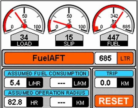
STEYR CONTROL CENTER - SCC
                                       User’s manual

IMPORTANT SAFETY AND LEGAL INFORMATION                                5
MAGNETISM – DANGER FOR APPLIANCES
NAVIGATION
PRECAUTIONS USING THE TOUCH SCREEN

ABBREVIATIONS                                                         6

INSTALLATION                                                          7
DASHBOARD/FLUSH MOUNTING
BRACKET MOUNTING
CONNECTING CABLES
WIRING EXAMPLES

USING THE STEYR CONTROL CENTER                                   12
GPS DISPLAY
MENU
INFORMATION AREA

MENUS                                                            15
MAIN MENU
TANK MENU
FUEL GAUGE
TANK INFORMATION
MANUAL TANK
CALCULATED VALUES
TRIP INFORMATION
ENGINE MENU
I/O-BOX MENU
RELAYS
SENSOR INPUTS
NAME OF SELECTED I/O-BOX
SELECTING OTHER I/O-BOXES
DIAGRAM
SETTINGS
SYSTEM INFORMATION
BRIGHTNESS
TIME ADJUST
UNITS
ALARMS
HELP SCREEN
SPECIAL FUNCTIONS
ADJUSTING THE TOUCH SCREEN
CONFIGURATION

CLEANING THE STEYR CONTROL CENTER                                27

Z001071/0-05-090121_MAD                                Page 2 of 30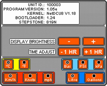
STEYR CONTROL CENTER - SCC
                                 User’s manual

CLEANING THE DISPLAY
CLEANING THE CASE
WARRANTY

CE CONFORMITY                                              28

FREQUENTLY ASKED QUESTIONS                                 29

Z001071/0-05-090121_MAD                          Page 3 of 30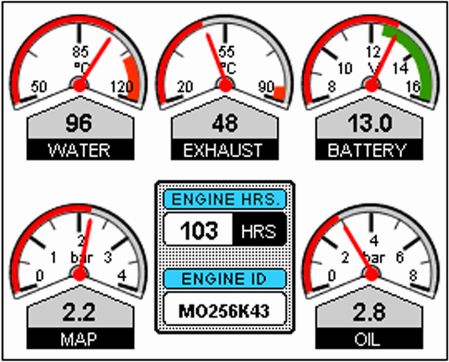
STEYR CONTROL CENTER - SCC
                                 User’s manual

Z001071/0-05-090121_MAD                          Page 4 of 30
STEYR CONTROL CENTER - SCC
                                        User’s manual

Important safety and legal information
Under no circumstances shall STEYR MOTORS or any of its subsidiaries or any of its
external suppliers accept liability for any loss of data, income, incidental damage or
consequential losses incurred as a result of the use of the product whosoever caused
when used as a monitor for electronically controlled engines or other systems even if
the information shown on the display are wrong.

Magnetism – danger for appliances
The protection cover has built in two strong neodymium magnets.
These magnets are much stronger than "ordinary" magnets. Keep a safe distance
between the magnets and all appliances and objects that can be damaged by
magnetism. This includes, amongst other things, television and computer monitors,
credit cards, diskettes and other data devices, video tapes, mechanical clocks, hearing
aids and loud speakers. Pacemakers can be disturbed by large magnets - exercise
caution. The magnets can also influence your compass. Keep enough distance
between the magnets and your compass.

Navigation
The GPS coordinates are only aid to navigation. Its accuracy can be affected by many
factors, including equipment failure or defects, environmental conditions, and improper
handling or use. It is the user’s responsibility to exercise common prudence and
navigational judgment.
Always check that your route to a waypoint is safe before traveling towards it.

Precautions using the touch screen
The touch screen of the SCC is a sensitive electronic device. Use your fingers or a
suitable stylus of the type used for PDA’s.
Do not use sharp or hard things such as ball pens.

Z001071/0-05-090121_MAD                                                      Page 5 of 30
STEYR CONTROL CENTER - SCC
                                        User’s manual

Abbreviations
CAN          Controller Area Network     Serial communication protocol
ECU          Engine Control Unit         This is the electronic box mounted on your
                                         STEYR MOTORS engine. It controls the
                                         engine and reports information to the SCC.
GPS          Global Positioning System
I/O-Box      Input/Output box            Optional box to connect sensors and to
                                         switch loads.
SCC          STEYR CONTROL CENTER

Z001071/0-05-090121_MAD                                                  Page 6 of 30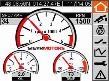
STEYR CONTROL CENTER - SCC
                                        User’s manual

Installation

Dashboard/flush mounting
    •   Select an appropriate place in your dashboard.
        IMPORTANT: To avoid overheating of the SCC in direct sunlight ensure
        enough air ventilation behind the SCC. There must be a space of at least
        10cm/4inch behind the SCC.
    •   Take the flush mounting template and check the dimensions before using it.
        Dimensions may differ because of the printing or photocopying process.
    •   Mark the positions for the four drill holes on the edges.
    •   Drill the four holes
    •   Mark the cut out from one drill hole to the next.
    •   Check dimensions. Be sure not to cut out too large!
    •   Cut out the rectangle
    •   Attach the two mounting brackets type A on the SCC
    •   Put the SCC into the cutting
    •   Prepare mounting bracket type B: Screw the nut on the fixing screw – screw the
        fixing screw into the mounting bracket type B and screw the rubber spacer on
        the fixing screw as far as it will go.
    •   Attach the two mounting brackets type B on the SCC and screw them down on
        the SCC with the four mounting screws. The rubber spacer should not touch the
        dashboard so far. Also take care that there is a gap between the rubber spacer
        and the mounting bracket type A.
    •   Screw down the two fixing screws. When the rubber spacer touches the
        dashboard turn on the fixing screws about two more revolutions. The required
        torque is 0.8Nm. Do not over tighten the fixing screws! The rubber spacers
        mustn’t be pressed together more than 1mm (0.04 inch). Take care to leave a
        gap between the front of the dashboard and the SCC.
    •   Counter the fixing screw with the nut.

Z001071/0-05-090121_MAD                                                     Page 7 of 30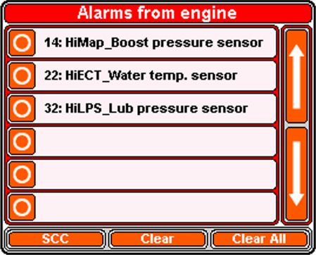
STEYR CONTROL CENTER - SCC
                                          User’s manual

Leave a gap –
Very important!
                                                                         SCC
Dashboard

Rubber spacer                                                      Mounting bracket
                                                                   type A

Mounting bracket
type B

                           Fixing screw      Nut    Mounting screw

           Before fixing                            After fixing

                                               min.
  height h                                     h - 1mm
                                               (h - 0.04”)

                min. 1mm (0.04”)

Bracket mounting
Please refer to the mounting instructions delivered with the optional bracket mounting
set.

Z001071/0-05-090121_MAD                                                      Page 8 of 30
STEYR CONTROL CENTER - SCC
                                         User’s manual

Connecting cables

The SCC has three built in plugs on the back side.

4pin connector            Power supply and data from the STEYR MOTORS Panel.
                          Use any one of the two 4pin connectors of the SCC.
4pin connector            Plug with termination resistor or
                          connect I/O-Box or
                          connect another SCC.
                          The last SCC or I/O-Box of the chain must have the plug
                          with the terminations resistor connected
6pin connector            Connect the GPS-receiver.
                          For configuring the SCC you can also connect the USB
                          cable here instead of the GPS receiver. The USB-cable is
                          part of the STEYR CONTROL CENTER USB Config Kit
                          (SMO part number: VR00155/0).
                          If unused leave the 6pin plug (delivered with the SCC) with
                          all the sealing plugs in place for sealing purposes.

New STEYR MOTORS panels are delivered with a 4pin Deutsch plug. These are plug
and play compatible with the SCC. If you own a panel with an 8pin Deutsch plug you
need to change it into a 4pin connector. Please contact your local dealer to obtain a
conversion kit.

Z001071/0-05-090121_MAD                                                       Page 9 of 30
STEYR CONTROL CENTER - SCC
User’s manual
Wiring examples
GPS
Connect termination
Panel SCC plug 2070.03!
Cable 2070.06
Panel 1m
Simple configuration: 1 SCC and a GPS receiver
Connect termination
GPS plug 2070.03!
Panel SCC I/O-Box
Cable 2070.06 Cable 2070.02
Panel 1m Power/CAN 3m
Configuration with 1 SCC, 1 I/O-Box and a GPS receiver
Z001071/0-05-090121_MAD Page 10 of 30STEYR CONTROL CENTER - SCC
User’s manual
GPS
Panel SCC I/O-Box
Cable 2070.06 Cable 2070.02
Panel 1m Power/CAN 3m
I/O-Box
SCC I/O-Box
Connect termination
plug 2070.03!
Configuration with 2 SCC and 3 I/O-Boxes
In this configuration one SCC must be declared as master and the other as slave.
Please contact your local dealer for configuring your SCC.
The GPS receiver can be connected to either SCC. It’s also possible to connect a
GPS receiver at either SCC.
The sequence of the devices (SCCs + I/O-Boxes) connected does not matter. You can
also use e.g. following sequences:
Panel – SCC – SCC – I/O-Box – I/O-Box – Termination plug.
Panel – SCC – I/O-Box – SCC – I/O-Box – I/O-Box – Termination plug.
It’s possible to connect up to 6 I/O-Boxes on one panel.
Z001071/0-05-090121_MAD Page 11 of 30STEYR CONTROL CENTER - SCC
User’s manual
Using the STEYR CONTROL CENTER
The SCC is supplied with a touch screen. When you press buttons shown on the
display, the SCC can react and perform an action. In typical installations the SCC gets
power when you turn on the ignition. You’ll see a welcome screen for a few seconds.
Then the SCC shows the main display – also called main menu.
GPS display
Menu
Information area
Z001071/0-05-090121_MAD Page 12 of 30STEYR CONTROL CENTER - SCC
User’s manual
GPS display
On the top you can see the GPS information. If you have connected a GPS receiver
and it is receiving data, you see the following kind of information:
Latitude and hemisphere N or S Course over ground
Current time
Longitude and hemisphere E or W (see also configuration
menu)
Menu
On the right the display shows you the menu bar. By simply pressing anyone of the
menu buttons it switches to the appropriate menu. When the main menu is active and
the hybrid engine is available, it’s possible to change between the main and hybrid
menu on repeated presses off the main menu button.
Main menu Hybrid menu
Tank menu
Engine menu
I/O-Box menu
Diagram
Settings
Alarms
Z001071/0-05-090121_MAD Page 13 of 30STEYR CONTROL CENTER - SCC
User’s manual
Information area
Here the information depending on the selected menu appears.
Z001071/0-05-090121_MAD Page 14 of 30STEYR CONTROL CENTER - SCC
User’s manual
Menus
Main menu
Speed (from GPS) Engine speed RPM (from ECU)
Lube oil pressure LOP Engine coolant temperature ECT
(from ECU) (from ECU)
Z001071/0-05-090121_MAD Page 15 of 30STEYR CONTROL CENTER - SCC
User’s manual
Hybrid menu
Hybrid mode Speed E-Motor Battery capacity
Current
Hybrid status
Hybrid temperature E-Engine temperature
Z001071/0-05-090121_MAD Page 16 of 30STEYR CONTROL CENTER - SCC
User’s manual
Tank menu
Engine load Slip Fuel gauge
Tank information
Trip information
Calculated values
Slip Calculation
This shows the difference of the actual and theoretical distance of
travel of the vessel. This can only be correctly indicated if a GPS
sensor is connected and the gearbox ratio and propeller pitch are
entered (See Configuration Software user manual Page 11)
Fuel gauge
This shows the remaining fuel of the selected tank.
When “Manual tank” is selected, this has a special function: Double-
click on the instrument and you can enter the volume of the tank and
the low alarm level. This information will only be used for the scale of
the manual tank instrument.
Z001071/0-05-090121_MAD Page 17 of 30STEYR CONTROL CENTER - SCC
User’s manual
Tank information
Here the selected Fuel level sensor or
“manual tank” is shown. By pressing this
button a dialogue appears where to select
the preferred tank. If no fuel level sensors are configured, then only “manual tank” can
be selected.
This box shows the actual contents of the selected tank.
When “manual tank” is selected, then you can press the button to
enter the actual contents of the tank. This value will then be shown
on the fuel gauge. As fuel is consumed the fuel gauge decreases.
Manual tank
When “manual tank” is selected, the current contents of the tank have to be entered
manually. This has to be done every time the tank is refueled. At the time of entering
the contents of the tank the fuel gauge takes this value. The fuel consumption reported
by the ECU will be automatically subtracted from this value. Take care not to enter too
high values. In this case you’d get no low fuel alert.
Calculated values
The shown values are computed and
actualized permanently.
The values per distance are only available
when GPS data are received.
Trip information
This shows the distance covered since powering up the SCC.
By pressing „RESET“ it will start from zero.
Z001071/0-05-090121_MAD Page 18 of 30STEYR CONTROL CENTER - SCC
User’s manual
Engine menu
Engine coolant Exhaust temperature Battery voltage
temperature ECT EXT (from ECU) (from ECU)
(from ECU)
Engine information
Manifold absolute (boost) Lube oil pressure LOP
pressure MAP (from ECU) (from ECU)
Z001071/0-05-090121_MAD Page 19 of 30STEYR CONTROL CENTER - SCC
User’s manual
I/O-Box menu
Previous I/O-Box Name of selected Next I/O-Box
I/O-Box
Relays
Gauge values show an
example only
Sensor inputs
This is the standard configuration of the relays and sensors label names, which can be
selected freely using the optional STEYR CONTROL CENTER USB Config Kit (SMO
part number: VR00155/0).
Relays
This shows one button for each relay of the selected I/O-Box. Pressing a relay button
turns on the connected device (e.g. horn, lamp …)
Sensor inputs
Here the value of each connected sensor is shown
Z001071/0-05-090121_MAD Page 20 of 30STEYR CONTROL CENTER - SCC
User’s manual
Name of selected I/O-Box
In this area you can see the name of the
selected I/O-Box. If there is no name assigned to
the I/O-Box, then the serial number of the
selected I/O-Box is shown.
By double
clicking
on the
name of
the
I/O-Box a
window
with more
informatio
n about
the
I/O-Box is
shown in
a popup
window.
Press OK
to
confirm.
Selecting other I/O-Boxes
With the two arrow buttons beside the name of the I/O-Box
you can select other connected I/O-Boxes to be displayed.
The relays and sensor inputs will show the corresponding values.
These buttons have no function if only one I/O-Box is connected.
Z001071/0-05-090121_MAD Page 21 of 30STEYR CONTROL CENTER - SCC
User’s manual
Diagram
Selection buttons
Curves
Three diagrams are shown, on the left there are three buttons. By pressing one of
them you can select another measurement to be shown in this diagram. The selected
value will be shown on the button and a new curve will be drawn.
The selected measurements are scanned on a cyclic basis. The current value is drawn
on the right side and the curve constantly moves to the left.
The following table shows the available measurements to be selected for the diagram
RPM Engine speed (revolutions per minute)
LOP Lube oil pressure
ECT Engine coolant temperature
VPWR Voltage power – supply voltage of the ECU
MAP Manifold absolute (boost) pressure
HRS Operating hours of the engine
LOAD Engine load
CMD Accelerator lever position
FUEL Current fuel consumption
TRIP Trip fuel consumption
CONS Total fuel consumption
EXT Exhaust (water) temperature
FPS Fuel per stroke
SPEED Speed from GPS
Z001071/0-05-090121_MAD Page 22 of 30STEYR CONTROL CENTER - SCC
User’s manual
Settings
System information
Brightness and
time adjust
Units
System information
This window shows the Unit ID (serial
number) and software versions of the
SCC.
Z001071/0-05-090121_MAD Page 23 of 30STEYR CONTROL CENTER - SCC
User’s manual
Brightness
Press “-” for lower brightness and to turn off the display
backlight. When the backlight is turned off nothing can
be read on the display. The next touch anywhere on the
touch screen will turn on the light again. By pressing “+” the backlight will switch to the
brightest position.
Time adjust
Please adjust the GPS time with these two buttons
according to your local time zone.
Units
Use these buttons to
change the units of the
instruments to your
needs. You can
change the units of
temperature, speed,
pressure and volume.
Z001071/0-05-090121_MAD Page 24 of 30STEYR CONTROL CENTER - SCC
User’s manual
Alarms
Current alarm/service code list (SCC or engine)
Previous/next
page
Switch shown list Clear selected Clear all
alarm
Whenever the ECU transmits a service code or the SCC registers an alarm, the Alarm
menu button becomes red. By pressing this button one of two possible lists
will be shown. This can be seen in the title: “Alarms from SCC” or “Service codes from
engine”.
With this button you can switch between the two lists.
If more events occur than can be shown at once, the up/down buttons can be used to
show all the entries.
By pressing an entry line you can select single alarms / codes.
Z001071/0-05-090121_MAD Page 25 of 30STEYR CONTROL CENTER - SCC
User’s manual
The Clear button deletes the selected entry. Remark: If the
alarm/service code still exists it will be added to the list again. In this case it seems as
though you can’t remove the entry. This is normal behavior.
For deleting entries a password is required. Use the unit ID as password. The unit ID
can be found in the system information window of the settings menu. The password
prevents unauthorized users from deleting entries. After leaving the alarms menu and
returning back the password is required again for deleting entries.
Use this button to clear all entries of the shown list. Entries in other
lists remain preserved. If any alarm/service code still exists it will be added to the list
again. In this case it seems as if you can’t remove some or all entries. This is normal
behavior. For information about the password see paragraph “Clear button” above.
When all alarms/service codes are removed, the alarm menu button appears in the
normal state. or .
Help screen
To get more information about the service codes from engine simply double-click on
an entry. A help screen appears which provides you with more information about this
service code.
Z001071/0-05-090121_MAD Page 26 of 30STEYR CONTROL CENTER - SCC
User’s manual
Special functions
Adjusting the touch screen
When it seems that the SCC doesn’t react properly to your presses it could be
necessary to calibrate the touch screen. Press and hold down somewhere on the
touch screen for more than 20 seconds. Release the touch screen.
The following screen appears:
Carefully press and briefly hold the
stylus on the center of the target.
Repeat this as the target moves around
the screen.
When calibration is completed this
window is shown.
Press the touch screen anywhere and
the SCC can be used as usual.
Z001071/0-05-090121_MAD Page 27 of 30STEYR CONTROL CENTER - SCC
User’s manual
Configuration
The SCC and I/O-Boxes can be configured using the configuration software which
runs on PCs with Windows XP. A separate configuration kit is available which includes
everything you need to connect to a PC and configure your SCC.
Cleaning the STEYR CONTROL CENTER
Cleaning the display
Take care when cleaning the display, to avoid damaging it.
• Do NOT wipe the display screen with a dry cloth, as this could scratch the
screen coating.
• Do NOT use acid, ammonia based or abrasive products.
Regularly clean your Display as follows:
1. Switch off the power to the Display.
2. Wipe the Display with a clean soft cloth. To remove oily finger marks use a spray
cleaning agent of the type used for cleaning spectacles.
Cleaning the case
Take care when cleaning the case, to avoid damaging it.
• Do NOT apply too high pressure to the case, especially near the display, as this
could damage the display.
Clean the case with a clean soft cloth, water and soap. For obstinate soiling, you can
carefully use a mild detergent, rinsing afterward with plenty of water.
Warranty
The STEYR CONTROL CENTER is classified as an electronic device and the
Warranty Conditions apply as specified in the STEYR MOTORS Marine Warranty
Conditions.
Z001071/0-05-090121_MAD Page 28 of 30STEYR CONTROL CENTER - SCC
User’s manual
CE CONFORMITY
This equipment has been tested and found to comply with the limits according to EN
55022 class B and EN 55024, pursuant to the CE rules.
This equipment generates, uses and can radiate radio frequency energy and, if not
installed and used in accordance with the instructions, may cause harmful interference
to radio communications. However, there is no guarantee that interference will not
occur in a particular installation. If this equipment does cause harmful interference to
radio or television reception, which can be determined by turning the equipment off
and on, the user is encouraged to try to correct the interference by one or more of the
following measures:
-Reorient or relocate the receiving antenna.
-Increase the distance between the equipment and receiver.
-Connect the equipment into an outlet on a circuit different from that to which the
receiver is connected.
-Consult the dealer or an experienced radio/TV technician for help.
Z001071/0-05-090121_MAD Page 29 of 30STEYR CONTROL CENTER - SCC
User’s manual
FREQUENTLY ASKED QUESTIONS
Q. Why are the changes that I make on the SCC not always saved?
A: Changes (Ex. metric system, temperature, pressure etc.) are saved as soon
as you change to a different screen mode (right hand task bar). Generally if
you change any parameters then always change screen modes before turning
the ignition off to make sure they are saved.
Q. Do I need special configuration software for the SCC?
A. Only if slip is to be calculated or an IO box is used SCC-Configuration KIT:
VR00155/0.
Q. Is the configuration software included in the standard SCC package?
A. No, it must be ordered separately – VR00155/0.
Q. It say I need Microsoft Active Sync, where do I find this
A. Please download free of charge under www.microsoft.com and search for
Active sync download.
Q. Which sensor types can be connected to the I/O Box?
A. Any and all resistor senders may be used in conjunction with the SCC, we
have standard settings for the senders that we supply (drop down menu when
configuring) but there is also the option to configure your own sender.
Q. How can I do parallel multiple SCC or SCC+ Analogue VDO panel installations?
A.: To use the SCC, you need only 4 cables; +12V DC and “Mass”, CAN-H and
CAN-L. This 4pol. connector is behind all STEYR Panels (=X24).
Q. Can I delete engine errors with the SCC
A. Yes, except for the 200 number errors which are generally not removable.
Q. Can the SCC store information like a log file
A. No, there is no accessible storage system on the units.
Q. How can I copy configurations from one SCC to another
A. With the Configuration software this can be done easily, after Saving the
settings in the STEYR Control Center Configuration, you can configure any
other displays. Please refer to the Configuration software user manual
Z001075/0 page 23 “transfer the configuration of an SCC in the pool onto the
connected SCC”
Z001071/0-05-090121_MAD Page 30 of 30You can also read