Smart Braking Actuator Control For A Heavy Weighted Electric Vehicle
←
→
Page content transcription
If your browser does not render page correctly, please read the page content below
Journal of Mechanical Engineering Research and Developments
ISSN: 1024-1752
CODEN: JERDFO
Vol. 44, No. 1, pp. 08-16
Published Year 2021

Smart Braking Actuator Control For A Heavy Weighted Electric
 Vehicle
 Sonki Prasetya†,‡, Hendri D.S. Budiono†, Ario Sunar Baskoro†, Agung Shamsuddin†,
 Danardono A. Sumarsono†*, Mohammad Adhitya†, Fuad Zainuri†‡, Nazaruddin†, Ghany
 Heryana†, Rolan Siregar†
 †
 Research Center for Advanced Vehicle (RCAVe), Universitas Indonesia, 16424, Indonesia.
 ‡
 Department of Mechanical Engineering Politeknik Negeri Jakarta 16425, Indonesia.

 *Corresponding Author Email: danardon@eng.ui.ac.id

ABSTRACT: One of essential feature in driving is the braking system. Buses as one of heavy vehicles commonly
use drum or disc brakes type to decelerate the speed. Heavy vehicles use air brake system via cylinders working
as the actuators to push the rod thus expand the braking shoe inside the brake drum. Nevertheless, Electric
Vehicles (EV) has another priority to save the energy stored in the battery. Meanwhile, generating pressurized air
using a compressor inside the bus also produces new problem namely energy consumption. Furthermore, air brake
system also increases inefficiency while EVs have to manage the energy usage carefully. Hence, an alternative
substitution of the conventional air system using direct electric actuator was developed. The idea is to use less
conversion of energy in order to increase efficiency as well as reduce components. However, the characteristic
between the conventional air system and electric system are different. Therefore, this study focuses on produce
the characteristic of the new system similarly with the conventional system in order to replace the component.
This study uses an intelligent method approach so called fuzzy to achieve the objective. The result shows that the
curve can be formed according to the previous system with improvement in dynamics. Furthermore, a braking
signal PWM signal is generated based on the result with 10ms period.

KEYWORDS: Braking, Electric Vehicles, Fuzzy, PWM.

INTRODUCTION

Mass transportations are essential for a city. A modern city has sufficient mass transportations for its citizens. A
bus is one of common mass transportation modes used in a city. It is considered as a heavy weighted vehicle.
Higher number of vehicles on the road also increases problems. According to WHO yearly statistic of people
injured due to accident is more than 1.3 million people [1]. Thus, a braking system is an important feature as the
accident preventive device in a vehicle. Mostly heavy weighted vehicles such as commercial buses and trucks use
air actuators as their main drive. This system either using drum or disc brake type requires several apparatuses
integrated to perform braking specifically air compressor, hosepipes, air reservoir, pneumatic regulators and also
cylinders inside the braking chamber. The air supply is generated by the compressor via the rotational part of the
combustion engine to be directed and conserved into air reservoir [2]. The braking chamber consists two related
compartments namely parking brake and service brake. At beginning, the parking brake must be filled with
pressurized air in order to release the connection with the service brake. Afterward, when a braking incident
happens the pneumatic cylinder inside the service brake moves the push-rod to inflate the brake-shoe with the
supply of the pressurized air [3].

Air actuator system has drawbacks when applied to electric buses. First, the vehicle energy consumption would
rise and reduce the capacity in the energy storage. Furthermore, several stages of conversion creates loses [4].
Hence, an electrical braking actuator as an alternative system is studied in [5]. The system can be applied using
the electromagnetic principle. This technique has been applied for several braking assembly namely fast trains,
magnetic hoist cranes, wheel chairs, and aerospace vehicle [6-9]. However, pneumatic systems have compressible
characteristics unlike typical electric actuators that can cause rapid movement during braking action. It is
unwanted considering the safety during driving. Therefore, this study focuses only on the braking actuator
specifically the service braking part. This research aim is to find the method/ algorithm system using an electric

 8
Smart Braking Actuator Control For A Heavy Weighted Electric Vehicle

actuator as the alternative system by adopting the behavior of the conventional pneumatic system. Therefore,
objectives to be achieved are to obtain the appropriate control for smooth braking with the integration of an
artificial intelligent method. Moreover, applying the algorithm to generate PWM signal method as the input of the
controlled magnetic solenoid.

LITERATURE REVIEW

Pneumatic braking characteristic in heavy vehicles follows the ISO 6358 standard [10]. The nature of pneumatic
cylinder as the braking actuator is shown in [11]. It has pressure response from 0 to the maximum pressure within
period of 0.6 second during emergency braking incident happens. Hence, the pneumatic brake experiences specific
delay to stop the vehicle from the minimum to its maximum intensity. However, this type of braking has losses
due to several step of stages. It is acceptable when used for combustion engine vehicles (CEVs) due to the
rotational part of the engine. Although the braking energy consumption is inefficient, filling the fuel as the energy
supply for CEVs takes only few periods and can easily find everywhere. This becomes essential problem when
applied to a heavy electric vehicle (EV). The heavy EV depend heavily on the energy storage namely battery for
the fuel needs. It is not as fast as the conventional vehicle when refilling the fuel. Therefore, energy consumption
must be carefully managed. Furthermore, the charging or swapping the battery facilities are not easily found
during the journey.

An alternative substitute of the heavy vehicle braking using direct electric power is studied. The solenoid is chosen
to be the actuator. A solenoid uses magnetic principle to pull or push ferromagnetic materials. In order to control
the movement of this braking actuator, electric power supply is required to generate the magnetic field. However,
solenoid type actuator has quick response when directly connected with electric power supply. It has different
characteristic when compared to the conventional pneumatic braking system. Furthermore, digital controller can
only use ‘on-off’ signal that results in sudden movement if directly applied to the electrical equipment such as
solenoid. It may be acceptable if applied to a system that vibration is not a big issue. However, this becomes
problem when applied to the passenger vehicles. Therefore, pulse width modulation (PWM) technique is utilized
in order to alternate the intensity of the magnetic field for moving the braking lever. PWM has been proven that
it can be applied to control the intensity of magnetic field via solenoid [12, 13]. The presence of advanced
technology supports people in their life activities. Artificial Intelligent (AI) applications have been used by
researches for sophisticated vehicles. The AI so called Support Vector Machine (SVM) method applied to braking
system assisted by vision has been studied in [14]. Moreover, the AI using visual and laser scanner processed by
computational interpretation is researched in [15]. Another AI for auto parking using low cost smart system for
vehicle also investigated by Heimberger to develop rebuilding 3D vision for auto parking [16].

Moreover, there are various intelligent techniques joined in machines by the scientists. Optimization can also
performed by the help of them namely Genetic Algorithm (GA), Particle Swarm Optimization (PSO), and also
fuzzy logic [17]. Fuzzy system is widely used for machine applications such as in controlling washing machines,
rice cookers as well as air conditioners. This last-mentioned method is widely applied in the area of electric
vehicles. In order to optimize energy consumption for an electric vehicle (EV) [18]. A research by Salmasi uses
Fuzzy Logic Control block to be compared with conventional control in hybrid EV [19]. Fuzzy is commonly used
due to its modest, effective and also less complex solution as utilized in Ferreira et al [20]. Furthermore, fuzzy
has been applied for solenoid as well [21]. Therefore, in order to generate the artificial response for braking action,
this method is chosen.

RESEARCH METHOD

The observed solenoid actuator braking system is arranged in Figure 1. It uses drum brake type test bed system to
be observed. The solenoid is connected to the push-rod in order to produce pulling motion to slack adjuster for
expanding the brake-shoe via a camshaft when braking incident happens. Thus, friction is created between brake-
shoe and the drum brake. A controller provides signal to the driver to energize the solenoid. The method for
activating signal to the solenoid is the main attention of this research. Therefore, a solenoid

 9
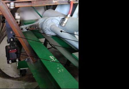
Smart Braking Actuator Control For A Heavy Weighted Electric Vehicle

 Figure 1. The electric brake arrangement.

This study compares the result between the direct method (on-off) and the fuzzy control. The authors created
Matlab Simulink blocks with two output results. Therefore, similar varying signal input are used for those two
methods to be observed as seen on Figure 2.

 Figure 2. The scheme of this study.

In order to create a characteristic of pneumatic actuator, the electric actuator must be adjusted. The period of
pneumatic braking cylinder supplies of around 0.5 ms from its minimum to its maximum pressure in the cylinder
due to piping transmission [22]. The controlled electric actuator made of solenoid coil. It applies electromagnetic
principle in order to pull the lever of braking system. Therefore, it applies Kirchhoff’s Voltage law [12, 23]:
 ( )
 ( ) = ( ) + (1)

where is the ( ), , , and ( ) are the voltage (V), resistance (Ω), inductance (H) and current (A) respectively.
The magnetic force to attract the conductor is induced by applying the voltage. It follows this formula with the
direction of linear motion [23, 24]. The generated magnetic can be calculated using formula (2) where flux
linkage (weber-turn of coil) and is the distance of plunger movement (m) effect the result.
 1 1
 = ∫0 ( , ) = ( ) 2 ( ) (2)
 2

The emphasis of this study is the process inside of the fuzzy control to generate the proper voltage. Hence, it
requires several stages. The steps are described in the Figure 3. It consists of three process namely fuzzification,
fuzzy rules, and defuzzification. The input firstly changed into linguistic fuzzy variable in the fuzzification stage.
The knowledge base gives important database to plot the linguistic control regulation. The rule is determined to
set the objective of control. It uses if/then operators as stated in Mamdani [25].

 10
Smart Braking Actuator Control For A Heavy Weighted Electric Vehicle

 Figure 3. Fuzzy system structure.

The fuzzification processes two input namely pedal pushed and pedal rate. It maps the input x ∈ {0,1}. The
membership function is usually formed into several shapes such as triangular, trapezoidal or sigmoid. The input
shape of first and second input variable universe in this paper uses trilateral functions. The first input is the pedal-
pushed signal (PP) means the intensity of braking pedal hit by the driver. When pedal is hit, the speed of hitting
the pedal (pedal rate) is considered as the second input (PR). The first input consists of three categories namely
minimum pushed (MinP), moderate pushed (ModP) and maximum pushed (MaxP) for PP.

 1, = 0
 ( ) = {0.5 − }
 , 0 ≤ ≤ 0.5
 0.5
 − 0.5
 , 0.1 ≤ ≤ 0.5
 0.4
 ( ) = 1, = 0.5
 0.9 −
 { 0.4 , 0.5 ≤ ≤ 0.9}
 −1
 , 0 ≤ ≤ 0.5
 ( ) = { 0.5 } (3)
 1, = 1
Furthermore, the second input divides the pedal rate into slow movement (SloM), moderate movement (ModM)
and fast movement (FasM).

 1, = 0
 ( ) = {0.5 − }
 , 0 ≤ ≤ 0.5
 0.5
 − 0.5
 , 0.1 ≤ ≤ 0.5
 0.4
 ( ) = 1, = 0.5
 0.9 −
 { 0.4 , 0.5 ≤ ≤ 0.9}
 −1
 , 0 ≤ ≤ 0.5
 ( ) = { 0.5 } (4)
 1, = 1
As an addition, the output variable universe uses mixed form curve triangular and trapezoidal function. It splits
into three categories namely minimum brake (MinB), moderate brake (ModB) and maximum Brake (MaxB). The
output is manipulated into the desired form in order to mimic the shape of conventional air cylinder movement.

 1, = 0
 ( ) = {0.7 − }
 , 0 ≤ ≤ 0.7
 0.7
 − 0.3
 , 0.3 ≤ ≤ 0.5
 0.2
 ( ) = 1, = 0.5
 0.7 −
 { 0.2 , 0.5 ≤ ≤ 0.7}

 11
Smart Braking Actuator Control For A Heavy Weighted Electric Vehicle
−1
, 0.3 ≤ ≤ 0.9
( ) = { 0.5 } (5)
1, 0.9 ≤ ≤ 1
Those previous functions can be represented in curves as seen on Figure 4. Figure (a) is the input function
meanwhile (b) is the output.
MinP ModP MaxP
Membership
1
MinB ModB MaxB
1
Membership
0 0.1 0.5 0.9 1
Pedal-Pushed (PP)
SloM ModM FasM
1
0 0.1 0.3 0.5 0.7 0.9 1
Membership
Braking Decision (Brake)
(b)
0 0.1 0.5 0.9 1
Pedal-rate (PR)
(a)
Figure 4. Membership function of input (a) and output (b)
In order to obtain the relationship between input and output, knowledge base rules are created. The look up table
to connect the premise and the consequences utilizes Mamdani method. This are rules used for the system.
1. If (PP is MinP) and (PR is sloM) then (Brake is MinB)
2. If (PP is MinP) and (PR is ModM) then (Brake is MinB)
3. If (PP is MinP) and (PR is FasM) then (Brake is ModB)
4. If (PP is ModP) and (PR is sloM) then (Brake is MinB)
5. If (PP is ModP) and (PR is ModM) then (Brake is ModB)
6. If (PP is ModP) and (PR is FasM) then (Brake is ModB)
7. If (PP is MaxP) and (PR is sloM) then (Brake is ModB)
8. If (PP is MaxP) and (PR is ModM) then (Brake is MaxB)
9. If (PP is MaxP) and (PR is FasM) then (Brake is MaxB)
RESULTS
The test utilizing two sine wave signals for the two varying input to observe the outcome of two method namely
conventional control and fuzzy control for the electric actuator. The first signal represents the intensity of pushed-
pedal (PP) and the second signal represents the speed(rate) of pedal hit (PR). It is simulated using the Matlab
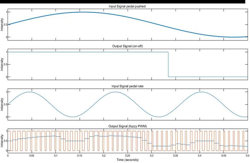
Simulink. The result is presented into four graphs into four rows to compare the output as seen on Figure 4.
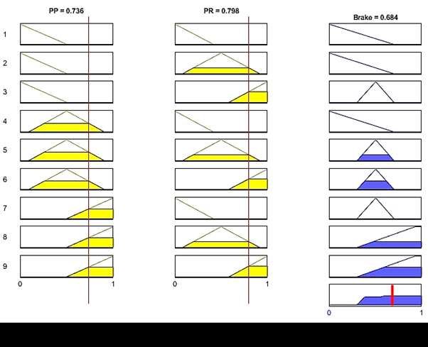
12Smart Braking Actuator Control For A Heavy Weighted Electric Vehicle Figure 4. Comparison result of conventional and fuzzy braking for an electric actuator. Those graph (Figure 4) shows that first row is the signal of pushed-pedal (PR), the second is the output when using direct “on-off” method of triggering the electric actuator, the third-row is the curve of pedal rate when hit, and the fourth row is the representation of fuzzy method of controlling electric actuator via PWM. The varying input signal of PR has less effect on the conventional method output since it only uses reference value to be compared with the PP signal in order to change the signal from “off” to “on”. It creates abrupt stop to the vehicle. Thus, it makes passengers inside the vehicle inconvenient or even endanger them. The combination between PP and PR as input in fuzzy control can alter the intensity of braking. PWM technique is utilized to implement this control for the triggering electric actuator. For instance, at 0.05s when the case of PP is almost the maximum intensity and PR is fast speed, around 10ms later (as the period required for processing) the result shows that the output at the maximum condition. At 0.3s where the PP is moderate intensity and PR is slow, the output signal gives minimum braking intensity. Furthermore, it also gives the low intensity of braking when PP is minimum level and PR is slow speed at 0.5s. The output curve of using fuzzy has more subtle dynamic of deceleration compare to the direct activation of the electric actuator. Therefore, passengers will not experience sudden movement inside the vehicle. The case when the crisp of first input PP has value of 0.7 and the second crisp input PR has value of 0.8, the output result is nearly 0.7 as seen in Figure 5. This is due to the first input value can be considered as the member of ModP and MaxP function, meanwhile the second input value can be considered as the member of ModM and FasM. Those two inputs undergo the combining process as stated in the determined rule. Therefore, they are acceptable for the rule number 5, 6, 8 and 9. According the rules number 5 and 6 have a similar output of moderate braking (ModB) meanwhile the other two rules (number 8 and 9) generate a maximum braking (MaxB) output. The output value is selected by comparing both the minimum membership value of the two inputs for each rule. Those selected input membership value is then plot to the output membership function. The area of the output is attained from the minimum membership input value from intersected value. Therefore, there are two output results from this case. In order to obtain the output value, both output areas are integrated. The integrated area uses centroid method to find the crisp output value. 13
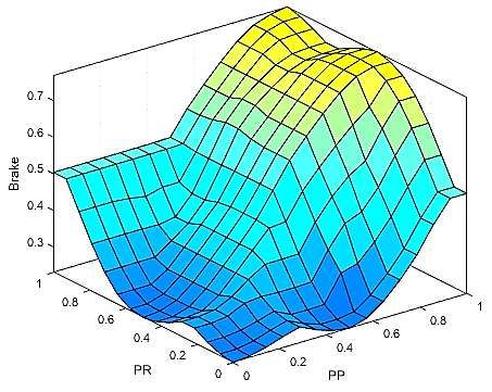
Smart Braking Actuator Control For A Heavy Weighted Electric Vehicle

 Figure 5. The crisp input of braking incident.

The three-dimensional surface of relationship between PP, PR and Brake is shown in Figure 6. The shape adopts
the form of braking pressure response in the pneumatic system. It reaches maximum when PP and PR are both at
maximum value. However, during the PR maximum, the brake response is moderate Brake (Mod B) for minimum
to moderate PP value.

 Figure 6. Surface of fuzzy inference system

 14
Smart Braking Actuator Control For A Heavy Weighted Electric Vehicle

CONCLUSIONS

Considering the outcomes presented previously, it can be concluded:

1. The comparison of signal between the direct activation and fuzzy control shows that direct activation without
 generation PWM only provides 1 signal to the electric actuator meanwhile the fuzzy control delivers various
 pulses with the period of 10ms to control the braking diversely.

2. The braking signal generated by fuzzy control shows better shape with gradual curves (analogous to the
 conventional pneumatic actuator response). Hence, it averts sudden stop when braking incident happens.

ACKNOWLEDGMENT

This work of research was supported by PUTI and PTUPT of Ristek-Dikti Research Grants. Many thanks for all
parties at the Universitas Indonesia and Politeknik Negeri Jakarta (was funded by PNBP Unggulan Prodi) which
provided facilities and opportunities to this study.

REFERENCES

[1] WHO, "Global Status Report on Road Safety 2018," World Health Organization, 2018.

[2] K. Holmberg, P. Andersson, N.-O. Nylund, K. Mäkelä, and A. Erdemir, "Global energy consumption due to
 friction in trucks and buses," Tribology International, vol. 78, pp. 94-114, 2014/10/01/ 2014.

[3] F. Bu and H. Tan, "Pneumatic Brake Control for Precision Stopping of Heavy-Duty Vehicles," IEEE
 Transactions on Control Systems Technology, vol. 15, no. 1, Pp. 53-64, 2007.

[4] A. Dietrich, "Electric actuators vs. pneumatic cylinders: A comparison based on total cost ownership,"
 Tolomatic, 2015.

[5] S. Prasetya, M. Adhitya, H.D. Budiono, and D.A. Sumarsono, "A investigation of braking system actuators
 for electric shuttle bus," in I-Trec, Bali, 2018, vol. 67, EDP Sciences.

[6] M. Hofmann, T. Werle, R. Pfeiffer, and A. Binder, "2D and 3D numerical field computation of eddy-current
 brakes for traction," IEEE Transactions on Magnetics, Vol. 36, No. 4, Pp. 1758-1763, 2000.

[7] Y. Yasa, E. Sincar, B.T. Ertugrul, and E. Mese, "A multidisciplinary design approach for electromagnetic
 brakes," Electric Power Systems Research, Vol. 141, Pp. 165-178, 2016/12/01/ 2016.

[8] B.V.R. Kumar, K. Sivakumar, Y.S. Rao, and S. Karunanidhi, "Design of a New Electromagnetic Brake for
 Actuator Locking Mechanism in Aerospace Vehcile," IEEE Transactions on Magnetics, Vol. 53, No. 11, Pp.
 1-6, 2017.

[9] N. Ebrahimi, P. Schimpf, and A. Jafari, "Design optimization of a solenoid-based electromagnetic soft
 actuator with permanent magnet core," Sensors and Actuators A: Physical, Vol. 284, Pp. 276-285,
 2018/12/01/ 2018.

[10] Pneumatic fluid power - Determination offlow rate characteristics of components using comprsible fluids,
 2013.

[11] T. Acarman, U. Ozguner, C. Hatipoglu, and A.M. Igusky, "Pneumatic Brake System Modeling for Systems
 Analysis," 2000. Available: https://doi.org/10.4271/2000-01-3414

[12] M. Taghizadeh, A. Ghaffari, and F. Najafi, "Modeling and identification of a solenoid valve for PWM control
 applications," Comptes Rendus Mécanique, Vol. 337, No. 3, Pp. 131-140, 2009/03/01/ 2009.

[13] P. Mahajan, P. Kalkundri, and A.S. Shaikh, "Precision Actuator Control for on/off Type Solenoid Valves
 using Pid Control Loop," in 2019 IEEE 5th International Conference for Convergence in Technology (I2CT),
 2019, Pp. 1-4.

[14] X. Wang, J. Tang, J. Niu, and X. Zhao, "Vision based Twostep Brake Detection Method for Vehicle Collision
 Avoidance," Neuro Computing Elsevier, 2016.

 15
Smart Braking Actuator Control For A Heavy Weighted Electric Vehicle

[15] D. Martin, "IVVI 2.0: An Intelliegent Vehicle based on Computational Perception," Expert Systems with
 Applications Elsevier, vol. 41, 2014.

[16] M. Heimberger, J. Horgan, C. Hughes, J.M. Donald, and S. Yogamani, "Computer Vision in Automated
 Parking Systems: Design Implementation and Challenges," Image and Vision Computing Elsevier, 2017.

[17] M. Imad, A. Hosseini, and H.A. Kishawy, "Optimization Methodologies in Intelligent Machining Systems -
 A Review," IFAC-PapersOnLine, Vol. 52, No. 10, Pp. 282-287, 2019/01/01/ 2019.

[18] O. Kraa, "A Novel Adaptive Operation Mode based on Fuzzy Logic Control of Electrical Vehicle," Energy
 Procedia, Vol. 50, Pp. 194-201, 2014/01/01/ 2014.

[19] F.R. Salmasi, "Control Strategies for Hybrid Electric Vehicles: Evolution, Classification, Comparison, and
 Future Trends," IEEE Transactions on Vehicular Technology, Vol. 56, No. 5, Pp. 2393-2404, 2007.

[20] A.A. Ferreira, J.A. Pomilio, G. Spiazzi, and L. d. A. Silva, "Energy Management Fuzzy Logic Supervisory
 for Electric Vehicle Power Supplies System," IEEE Transactions on Power Electronics, Vol. 23, No. 1, Pp.
 107-115, 2008.

[21] X. Fan, Y. He, P. Cheng, and M. Fang, "Fuzzy-Type Fast Terminal Sliding-Mode Controller for Pressure
 Control of Pilot Solenoid Valve in Automatic Transmission," IEEE Access, Vol. 7, Pp. 122342-122353,
 2019.

[22] F. Yang, G. Li, J. Hua, X. Li, and T. Kagawa, "A New Method for Analysing the Pressure Response Delay
 in Pneumatic Brake System Caused by the Influence of Transmission Pipes," Applied Sciences, Vol. 7, 2017.

[23] M.F. Badr, "Modelling and Simulation of a Controlled Solenoid," IOP Conference Series: Materials Science
 and Engineering, Vol. 433, Pp. 012082, 2018/11/30 2018.

[24] N. Ida, Engineering Electromagnetics, 3rd ed. Springer, 2015.

[25] E.H. Mamdani and S. Assilian, "An experiment in linguistic synthesis with a fuzzy logic controller,"
 International Journal of Man-Machine Studies, Vol. 7, No. 1, Pp. 1-13, 1975/01/01/ 1975.

 16
You can also read