PSD4XX POSITIONING SYSTEM - ETHERCAT - HALSTRUP-WALCHER GMBH
←
→
Page content transcription
If your browser does not render page correctly, please read the page content below
Bus description
PSD4xx positioning system – EtherCAT
General

halstrup-walcher GmbH
Stegener Straße 10
79199 Kirchzarten
Tel. +49 7661 39 63-0
info@halstrup-walcher.com
www.halstrup-walcher.com
© 2020, Kl

The manufacturer owns the copyright to this instruction manual. It contains technical data,
instructions and drawings detailing the device’s features and how to use them. It must not be
copied either wholly or in part or made available to third parties.
The instruction manual is part of the product. Please read this manual carefully, follow our
instructions, and pay special attention to the safety information provided. This instruction manual
should be available at all times. Please contact the manufacturer if you do not understand any
part of the instructions.
The manufacturer reserves the right to continue developing this device model without
documenting such development in each individual case. The manufacturer will be happy to
determine whether this manual is up-to-date.

7100.006514_Bus description_PSD4xx_EC_D_EN       2                                        05.05.2020
General

Table of Contents
1   General ......................................................................................................................... 4
2   Start-up ......................................................................................................................... 5
           2.1                                                                                                     .............6
           2.2      Switching on the device ....................................................................................6
           2.3      Generating the delivery state (without the control unit) .................................6
3   Description of EtherCAT .............................................................................................. 7
           3.1    EtherCAT interface with CoE protocol (CANopen over EtherCAT) .................7
           3.2    Status LEDs ........................................................................................................7
           3.3    Table of entries implemented from object dictionary .....................................9
           3.4    Table of device-dependent min., max. and default values ............................ 18
           3.5    Process data format ........................................................................................ 20
              3.5.1 Output module (from the perspective of the IO controller) ..................... 20
              3.5.2 Input module (from the perspective of the IO controller) ........................ 20
           3.6      Detailed description of status bits .................................................................. 20
           3.7      Detailed description of status bits .................................................................. 24
4   Functions .................................................................................................................... 25
           4.1    Positioning ....................................................................................................... 25
           4.2    Types of positioning ........................................................................................ 26
              4.2.1 Positioning run with reference loop ......................................................... 26
              4.2.2 Positioning run without reference loop .................................................... 27
              4.2.3 Manual run ................................................................................................. 27
           4.3      Velocity, acceleration and deceleration .......................................................... 27
           4.4      Maximum start-up and operating torque ....................................................... 28
           4.5      How to respond if the drive encounters an obstruction ................................ 28
           4.6      Response if drive is turned manually (adjustment function) ........................ 29
           4.7      Calculate the absolute physical position ........................................................ 30
           4.8      Set the spindle pitch ........................................................................................ 33
           4.9      Abort the run when the master fails ............................................................... 33
           4.10       Reference runs ............................................................................................. 34
           4.11       Run drive in reverse..................................................................................... 35
5   Technical data ............................................................................................................ 35

7100.006514_Bus description_PSD4xx_EC_D_EN                       3                                                        05.05.2020
General 1 General This bus description is to be used for the commissioning and integration of the drive into a field bus system. Technical data for the electrical connections of your drive can be found in the electrical connector and pin assignment description on the website: www.halstrup-walcher.de/technicaldocu 7100.006514_Bus description_PSD4xx_EC_D_EN 4 05.05.2020
Start-up

2     Start-up

     WARNING                Risk of injury if used inappropriately.
                            The device must be installed by trained technical personnel.

     WARNING                Risk of burns due to hot drive.
                            The drive can become very hot during operation.
                            Allow the drive to cool before touching it.

     WARNING                Risk of crushing due to rotary movement.
                            Do not reach into the working area of the drive when it is still
                            turning.
                            The user/operator must ensure appropriate protective
                            measures are taken.

     WARNING                Incorrect assembly can lead to the destruction of the drive.

     WARNING                Check that the supply lines are not pinched or crushed.
                            Lay the supply lines according to the general and specific local
                            assembly regulations.
                            If the supply lines have not been delivered together with the
                            device, please select suitable cables for the application.
                            Do not operate the positioning unit if the supply lines are
                            noticeably damaged.

     WARNING                Risk of injury. High contact voltages can occur in the case of
                            malfunctions.
                            This can be prevented by grounding.
     ATTENTION              The drive must be protected against excessive heating.
                            The user/operator must ensure appropriate protective measures are
                            taken.
     ATTENTION              Never apply force to the housing of the drive, e.g. for supporting
                            weight.

7100.006514_Bus description_PSD4xx_EC_D_EN     5                                        05.05.2020
Start-up
2.1 Setting the “Explicit Device ID” and the “Configured Station Alias”
The device’s “Explicit Device ID” can be set using the two rotary switches. (Address switch value
> 0). If the address is set to value 0, the “Explicit Device ID” can be set using SDO #2026. In this
case, the value is only accepted into the ESC and SII after saving (see SDO #204F) and
restarting.
Additionally a “Configured Station Alias” can be assigned via the bus of the EtherCAT master.
This value can also be set using SDO #2026. In this case, the value is only accepted into the ESC
and Sll after saving (see SDO #204F) and restarting.
2.2 Switching on the device
After connecting the supply voltage, you can begin positioning or manual runs immediately.
You can find information about installing the drive as well as electrical connections and pin
assignments at the following link: www.halstrup-walcher.de/technicaldocu
2.3 Generating the delivery state (without the control unit)
The drive can be reset to the delivery state even if no control unit is present.
This is done as follows:
1) Separate the device from the supply voltage.
2) Set the address switch to 98.
3) Switch on the device (control unit and motor voltage).
4) The yellow LED now flashes for 10 seconds at 10 Hz. If, during this time period, the
address is set to 99, the drive will reset all parameters to the delivery state, save this
setting and bring the axle to the mid-position.
5) Set the address switch to 00 in order to complete the delivery state.
6) Switch the device off.
The 10-second period will be ended early if any communication is established.
7100.006514_Bus description_PSD4xx_EC_D_EN 6 05.05.2020Description of EtherCAT
3 Description of EtherCAT
3.1 EtherCAT interface with CoE protocol (CANopen over EtherCAT)
The EtherCAT interface uses the CANopen over EtherCAT protocol in accordance with
ETG1000.6 Section 5.6:
One transmit and one receive SDO per device
One asynchronous transmit and receive PDO, active by default
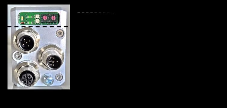
3.2 Status LEDs
The following LEDs are located under the sealing plug:
1 V_Motor Yellow LED = Motor supply voltage
2 P1L/A Green LED = Link/Activity
P2L/A Green LED = Link/Activity
3 Run Green LED = Signals the ESM status
Error Red LED = Signals an error
4 X10 Address switch x10
5 X1 Address switch x1
Meaning of the LEDs:
Yellow LED motor supply voltage (V_Motor)
Off Motor voltage too low or too high
On Motor voltage is OK
Flashing at 0.5 Hz Motor voltage is OK and drive is in the delivery state
7100.006514_Bus description_PSD4xx_EC_D_EN 7 05.05.2020Description of EtherCAT Each of the ports (P1/P2) has an associated green LED for the “Link” and "Activity" states. For each port (P1/P2), the following states are possible: Off No connection On Line connection is active, no data activity Flashing at 10 Hz Line connection is active, data transfer active The green “Run” LED signals the ESM status: Off INIT Flashing at 2.5 Hz PRE-OPERATIONAL Flashing at 1 Hz SAFE-OPERATIONAL On OPERATIONAL The red “Error” LED signals an error: Off No error Single flashes at 1 Hz Local error, application is changing ESM status Double flashes at 1Hz Watchdog timeout Flashing at 2.5 Hz Configuration error 7100.006514_Bus description_PSD4xx_EC_D_EN 8 05.05.2020
Description of EtherCAT
3.3 Table of entries implemented from object dictionary
Name, Index Function Range Backup? Delivery R/W
designation no. of state
values
Device type 1000 Device type 0 0 R
Software 100A Identifies the software of the R
description EtherCAT drives; returns the string
“PSD4xxIE/ECAT” when read
Identity 1018 Sub index 0: No. of indices (= 4) 8 bit 4 R
Sub 1: Vendor-ID (= 0x000002D8) 32 bit R
Sub 2: Product code 32 bit R
Sub 3: Revision number 32 bit R
(= 0x00010000)
Sub 4: Serial number 32 bit R
Receive PDO 1600 Sub index 0: No. of indices (= 2) 8 bit 2 R
1 mapping Sub 1: 0x20240010 32 bit R
Sub 2: 0x20010020 32 bit R
Transmit PDO 1A00 Sub index 0: No. of indices (= 3) 8 bit 3 R
1 mapping Sub 1: 0x20250010 32 bit R
Sub 2: 0x20300010 32 bit R
Sub 3: 0x20030020 32 bit R
SM Comm 1C00 Sub index 0: No. of indices (= 4) 8 bit 4 R
Types Sub 1: SM0 (= 1) 8 bit R
Sub 2: SM1 (= 2) 8 bit R
Sub 3: SM2 (= 3) 8 bit R
Sub 4: SM3 (= 4) 8 bit R
SM0 PDO 1C10 Sub index 0: No. of indices (= 0) 8 bit 0 R
Assignment
SM3 PDO 1C13 Sub index 0: No. of indices (= 1) 8 bit 1 R
Assignment Sub 1: 0x1A00 (1. TxPDO) 16 bit
General 2000 10 general purpose registers R
purpose 0...10 Sub index 0: No. of indices (= 10) 8 bit 10 R/W
register Sub 1…10: free register 16 bit Yes 0
Target value 2001 Target position in 1/100 mm (for a 31 bit No 0 R/W
4mm spindle and default values of
numerator, (SDO #2010) and
denominator (SDO #2011)).
This value can only be written in the
"pre-operational" state.
7100.006514_Bus description_PSD4xx_EC_D_EN 9 05.05.2020Description of EtherCAT
Name, Index Function Range Backup? Delivery R/W
designation no. of state
values
Actual value 2003 Current actual position in 1/100 mm 31 bit No R/W
(for a 4mm spindle and default values
of numerator, (SDO #2010) and
denominator (SDO #2011)).
Writing to this index number causes
the current position to be “referenced”
to the transferred value
Writing only possible when at a
standstill.
Referencing 2004 Correction factor for the target, actual 31 bit Yes 0 R/W
value and end limit values
Writing only possible when at a
standstill.
Drag error 2005 Reserved
Positioning 2006 Permissible difference between target 1...100 Yes 2 R/W
window and actual values for the “target 16 bit
position reached” bit in 1/100 mm
(for a 4mm spindle and default values
of numerator and denominator)
The maximum setting value changes
according to the same factor as the
resolution.
Writing only possible when at a
standstill.
Position 2010 These values allow you to apply any 1...1000 Yes 400 R/W
scaling, resolution to the drive that you wish. 0
numerator 16 bit
Position 2011 For a numerator factor of 400, the 1...1000 Yes 400 R/W
scaling, spindle pitch/resolution is stated in the 0
denominator denominator factor 16 bit
e.g.: Spindle pitch 1.5mm with
resolution 1/100 mm:
numerator = 400, denominator = 150
Writing only possible when at a
standstill.
7100.006514_Bus description_PSD4xx_EC_D_EN 10 05.05.2020Description of EtherCAT
Name, Index Function Range Backup? Delivery R/W
designation no. of state
values
Target speed 2012 Maximum rpm to be used for See Yes See R/W
positioning runs chap. chap.
Value in rpm 3.4 3.4
16 bit
Target speed 2013 Maximum rpm to be used for manual See Yes See R/W
for manual runs; value in rpm chap. chap.
run 3.4 3.4
16 bit
Maximum 2014 Applies after the end of the start-up See Yes See R/W
torque phase (during the start-up phase, the chap. chap.
value of parameter #2018 applies); 3.4 3.4
value in cNm 16 bit
Upper limit 2016 Maximum permitted target position 31 bit Yes 101200 R/W
Permissible values: (upper mapping
end - 1200.. 1611600 *
numerator/denominator)
For models with an auxiliary gearbox,
the range of values is reduced in
accordance with the gear ratio.
Writing only possible when at a
standstill.
Lower limit 2017 Min. permitted target position 31 bit Yes 1200 R/W
Permissible values: (upper mapping
end - 1200..1611600 *
denominator/numerator)
For models with an auxiliary gearbox,
the range of values is reduced in
accordance with the gear ratio.
Writing only possible when at a
standstill.
Maximum 2018 Value in cNm See Yes See R/W
start-up chap. chap.
torque 3.4 3.4
16 bit
Time period 2019 Time period during which the max. 10... Yes 200 R/W
for start-up start-up torque (SDO #2018) is 1000
torque applied 16 bit
Value in ms
7100.006514_Bus description_PSD4xx_EC_D_EN 11 05.05.2020Description of EtherCAT
Name, Index Function Range Backup? Delivery R/W
designation no. of state
values
Speed limit 201A Value in % of the target speed 30...90 Yes 30 R/W
for aborting 16 bit
run
Time elapsed 201B Value in ms 50...500 Yes 200 R/W
until speed 16 bit
falls below
speed limit for
aborting run
Acceleration 201C Value in rpm per sec. See Yes See R/W
chap. chap.
3.4 3.4
16 bit
Deceleration 201D Value in rpm per sec. See Yes See R/W
chap. chap.
3.4 3.4
16 bit
Length of loop 201F Minimum number of increments, in 0.025… Yes 250 R/W
which the drive runs to a target in a 10
specified direction. rotations
or
Value in increments (0 no loop)
-0.025…
The sign determines the direction of -10
the loop: (positive reference loop to rotations
larger values; negative reference or
loop to smaller values)
31 bit
Acceleration 2020 Reserved
2
Deceleration 2021 Reserved
2
Control word 2024 Bit 0: Manual run to larger values 16 bit No 0 R
Bit 1: Manual run to smaller values
Bit 2: Transfer target value
Bit 3: Reserved
Bit 4: Release: the axle will only
run if bit is set.
Bit 5: Reserved
7100.006514_Bus description_PSD4xx_EC_D_EN 12 05.05.2020Description of EtherCAT
Name, Index Function Range Backup? Delivery R/W
designation no. of state
values
Bit 6: Run without a reference
loop
Bit 7: Reserved
Bit 8: Reserved
Bit 9: Reserved
Bit 13: Toggle bit
All other bits must be set to 0
This value can only be written in the
"pre-operational" state.
Status word 2025 Bit 0: Target position achieved 0… R
FFFFh
Bit 1: Reserved 16 bit
Bit 2: Toggle bit
Bit 3: Reserved
Bit 4: Power supply to motor
available
Bit 5: Positioning run aborted
Bit 6: Drive is running
Bit 7: Max temp. exceeded
Bit 8: Run in opposite direction to
loop
Bit 9: Error
Bit 10: Positioning error
(obstruction)
Bit 11: Manual rotation
Bit 12: Incorrect target value
Bit 13: Power was unavailable to
motor
Bit 14: Positive range limit
Bit 15: Negative range limit
7100.006514_Bus description_PSD4xx_EC_D_EN 13 05.05.2020Description of EtherCAT
Name, Index Function Range Backup? Delivery R/W
designation no. of state
values
Address 2026 Explicit Device ID 16 bit Yes 0 R/W
Write:
When writing, the value is only
accepted into the ESC and Sll after
saving (see SDO #204F) and
restarting.
This value will only be used
if the address switches are set to
value 0.
Upper 2028 Definition of the positioning range 31 bit Yes 102400 R/W
mapping end relative to the absolute value encoder
Permissible values:
(actual position + 3 rotations) …
(actual position + 4029 rotations)
Writing only possible when at a
standstill.
Maximum 202B Holding torque at standstill in cNm See Yes See R/W
holding (after the phase “max. holding torque chap. chap.
torque at end of run”) 3.4 3.4
16 bit
Direction of 202C 0: Clockwise rotation to larger values 0 or 1 Yes 0 R/W
rotation 16 bit
(if looking at the output shaft)
1: Anti-clockwise rotation to larger
values
Writing is only possible when at a
standstill.
Idle period 202E Reserved
Actual speed 2030 Value in rpm 15 bit R
Maximum 2031 Maximum torque occurring during the 16 bit R
torque most recent run (the start-up phase,
during which the start-up torque
applies, see SDOs #2018/2019, and
braking phase are not taken into
account)
Value in cNm
Actual 2033 Current torque in cNm 16 bit R
torque
7100.006514_Bus description_PSD4xx_EC_D_EN 14 05.05.2020Description of EtherCAT
Name, Index Function Range Backup? Delivery R/W
designation no. of state
values
U control 203A Current supply voltage to control unit, 16 bit R
in 0.1 V
U motor 203B Current supply voltage to motor, in 16 bit R
0.1 V
UMot limit 203C Voltage limit for bit 4 (“Power supply 180… Yes 185 R/W
to motor available”); in 0.1 V 240
A positioning run or manual run can 16 bit
only begin if the motor voltage is
higher than the value set here. During
the run, the voltage may fall to 17.5 V.
UMot filter 203D Average time for motor voltage 100… Yes 100 R/W
measurement; in ms 1000
16 bit
Temp. limit 203E Upper temperature limit in °C 10...80 Yes 80 R/W
16 bit
Device 203F Internal device temperature in °C 16 bit R
temperature
Production 2040 Year and week of manufacture YYWW R
date (given as an integer) 16 bit
Serial number 2041 Device serial number 0… R
65535
16 bit
Max. holding 2042 Value in cNm See Yes See R/W
torque at end chap. chap.
of run 3.4 3.4
16 bit
Duration of 2043 Time period during which the holding 0...1000 Yes 200 R/W
max. holding torque is applied at completion of run 16 bit
torque at end (value in ms)
of run
Waiting time 2045 Reserved
for brakes
Drag error 2046 Reserved
correction
Readjustment 2047 Adjustment when at a standstill 0…1 Yes 0 R/W
0 off; 1 on 8 bit
7100.006514_Bus description_PSD4xx_EC_D_EN 15 05.05.2020Description of EtherCAT
Name, Index Function Range Backup? Delivery R/W
designation no. of state
values
Configuration 2049 Reserved
for connection
failure
Safe position 204A Reserved
for connection
failure
Repeat time 204B Reserved
for safety run
Device type 204D Device type within the PSD range as R
a string (e.g. “PSD403-18-H”)
Version 204E Software version number 16 bit R
Delivery state 204F Writing a “-6”: -6...-1 or No R/W
1
Resets the drive (corresponds to
switching the control voltage off and (during
on again) writing)
Writing a “-5”: ±15 bit
Sets the values of all parameters to
the delivery state, saves the
parameters in EEPROM, then
positions the drive in the middle of the
measurement range *)
(Station name and IP address are not
affected)
Writing a “-4”:
Sets the values of all parameters to
the last values saved by the user,
then positions the drive in the middle
of the measurement range *)
(Station name and IP address are not
affected)
Writing a “-3”:
Sets the values of all parameters to
the delivery state, deletes the station
name and IP address and saves the
parameters in EEPROM
7100.006514_Bus description_PSD4xx_EC_D_EN 16 05.05.2020Description of EtherCAT
Name, Index Function Range Backup? Delivery R/W
designation no. of state
values
Writing a “-2”:
Sets the values of all parameters to
the last values saved by the user,
without saving the parameters in
EEPROM
(Station name and IP address are not
affected)
Writing a “-1”:
Sets the values of all parameters to
the delivery state, without saving the
parameters in EEPROM
(station name and IP address remain
unaffected)
Writing a “1”:
Saves the parameters in EEPROM
Writing only possible when at a
standstill.
*) The positioning run to the middle of the measurement range can be aborted at any time by
setting control word = 0 with SDO #2024 (if state is not "operational") or via the PDO control word.
Furthermore, in “operational” state, the PDO control word is ignored during the positioning run to
the middle of the measurement range (unless it changes). Thus, a run to the middle of the range
can also be aborted by changing the PDO control word. Run commands issued before the
positioning run to the middle of the range will not be automatically resumed after this run has been
completed, (i.e. the PDO control word 0x14 and the old target value do not result in the drive
moving to this position).
7100.006514_Bus description_PSD4xx_EC_D_EN 17 05.05.2020Description of EtherCAT
3.4 Table of device-dependent min., max. and default values
Note: The operating torque setting is optimised for the nominal rated speed of the
respective device model. The more the set speed deviates from the nominal rated
speed (rpm), the greater the actual difference between the actual power consumption of
the motor circuit and the set value.
Note: Setting the value for the max. holding torque to 0 results in a maximum current
consumption by the motor circuit of approx. 50 mA
Device type PSD401 / PSD401 / PSD403 / PSD422 / PSD422 /
PSD411 PSD411 PSD413 PSD432 PSD432
- 5V - 8H/14H - 8H/14H - 8V - 8H/14H
Name Index Range of values
no. Delivery state
Upper mapping 2028 806,400 806,400 198,498 806,400 806,400
end*)
Upper limit*) 2016 805,200 805,200 197,298 805,200 805,200
Lower limit*) 2017 -805,200 -805,200 -197,299 -805,200 -805,200
Target speed for 2012 1…800 1…500 1…250 1…1000 1…500
positioning run 200 200 50 200 200
Target speed, 2013 1…800 1…500 1…250 1…1000 1…500
manual run 70 70 17 70 70
Acceleration 201C 1…5000 1…5000 1…1250 1…5000 1…5000
1000 1000 250 500 500
Deceleration 201D 1…5000 1…5000 1…1250 1…5000 1…5000
2000 2000 500 2000 2000
Maximum 2018 30…90 30…90 115…350 50…240 50…240
start-up torque 50 50 190 120 120
Maximum torque 2014 30…80 30…80 115…300 50…240 50…240
40 40 150 100 100
Maximum 2042 0…80 0…80 0…325 0…200 0…200
holding torque at 30 30 120 70 70
end of run
Maximum 202B 0…60 0…60 0…245 0…150 0…150
holding torque 20 20 80 50 50
7100.006514_Bus description_PSD4xx_EC_D_EN 18 05.05.2020Description of EtherCAT
Device type PSD426 / PSD428 /
436 438
- 14H - 14H
Name Index Range of values
no. Delivery state
Upper mapping 2028 256,000 196,683
end*)
Upper limit*) 2016 254,800 195,483
Lower limit*) 2017 -254,800 -195,483
Target speed for 2012 1…317 1…250
positioning run 63 50
Target speed, 2013 1…317 1…250
manual run 22 17
Acceleration 201C 1…1587 1…1250
150 125
Deceleration 201D 1…1587 1…1250
635 500
Maximum 2018 150…720 195…935
start-up torque 360 465
Maximum torque 2014 150…720 200…935
300 400
Maximum 2042 0…630 0…820
holding torque at 220 285
end of run
Maximum 202B 0…470 0…615
holding torque 155 205
*) The min. and max. parameter values cannot be specified because they are dependent on the
current scaling. The value is valid for the standard scaling (400 increments per revolution).
7100.006514_Bus description_PSD4xx_EC_D_EN 19 05.05.2020Description of EtherCAT
3.5 Process data format
3.5.1 Output module (from the perspective of the IO controller)
Bit Byte Meaning Corresponding SDO index number
0-15 0.1 Status word 2025h
16-31 2-3 Current rpm 2030h
32-63 4-7 Actual value 2003h
Note: Assignment (cannot be modified)
3.5.2 Input module (from the perspective of the IO controller)
Bit Byte Meaning Corresponding SDO index number
0-15 0.1 Control word 2024h
16-47 2-5 Target value 2001h
Note: Assignment (cannot be modified)
3.6 Detailed description of status bits
Bit 0: Target position reached
This bit is set:
- When a transferred target position has been reached successfully (not at
the end of a manual run, except when the target position is also the
specified limit)
- As a result of manual displacement during standstill, if the actual position of
the drive is once again within the positioning window
If bit 0 is set at the same time as bit 10 (obstruction), bit 0 has priority!
This bit is reset:
- After transferring a target position when the difference from the actual value
is larger than the positioning window (SDO #2006)
- By a manual run
- If an invalid target value has been transferred
- As a result of manual displacement during standstill
7100.006514_Bus description_PSD4xx_EC_D_EN 20 05.05.2020Description of EtherCAT
Bit 1: Reserved
Bit 2: Toggle bit:
This bit is set:
- If bit 13 of the control word is set
This bit is reset:
- If bit 13 of the control word is deleted
Bit 3: Reserved
Bit 4: Power supply to motor available
This bit is set:
- If the supply voltage for the motor is above the UMot limit (SDO #203C) and
below 30V
This bit is reset:
- If the supply voltage for the motor is below the UMot limit or above 30V
Bit 5: Positioning run aborted
This bit is set:
- If a positioning run is aborted because the release has been withdrawn in
the control word or due to an invalid bit combination in the control word
This bit is reset:
- For every new run command
Bit 6: Drive is running
This bit is set:
- When the drive is rotating
This bit is reset:
- When the drive is at a standstill
Bit 7: Temperature too high
This bit is set:
- When the internal device temperature exceeds the limit specified in
SDO #203E
7100.006514_Bus description_PSD4xx_EC_D_EN 21 05.05.2020Description of EtherCAT
This bit is reset:
- When the internal device temperature falls below the limit value by 5°C
Bit 8: Run in opposite direction to loop
This bit is set:
- After power up or a reset (a lash in a driven spindle which might be present
has not yet been eliminated)
- When initiating a positioning run or manual run in the opposite direction to
the reference loop
This bit is reset:
- When SDO #201F=0 and a positioning run or manual run is initiated
- When a transferred target position has been reached successfully in the
direction of the reference loop (not after a manual run)
Bit 9: Error bit
This bit is set:
- When an internal problem is detected when calculating the position
No run commands may be transmitted when the error bit is set!
This bit is reset:
- Only possible by resetting the drive
Bit 10: Positioning error (obstruction)
This bit is set:
- If a positioning run or manual run is aborted because the device is
overloaded (obstructions, extreme difficulty running)
If bit 0 (target position reached) is set at the same time as bit 10
(obstruction), bit 0 has priority!
This bit is reset:
- For every new run command
7100.006514_Bus description_PSD4xx_EC_D_EN 22 05.05.2020Description of EtherCAT
Bit 11: Manual rotation
This bit is set:
- If, while at a standstill, the drive is turned by an external force by more than
the value in the positioning window, after a positioning run has been
finished successfully
This bit is reset:
- For every new run command
Bit 12: Incorrect target value
This bit is set:
- If a transferred target value lies outside the range limits, caused e.g. by the
current reference value (SDO #2004)
- If a transferred target value lies within the range limits, but would leave the
specified range during the required reference loop
This bit is reset:
- For every new run command
Bit 13: Power was unavailable to motor
This bit is set:
- If the motor voltage is less than the UMot limit (SDO #203C) or above 30V
when initiating a positioning run or manual run
- If the motor voltage leaves the specified range during the run
This bit is reset:
- If the motor voltage is greater than the UMot limit and under 30V when
initiating a positioning run or manual run
Bit 14/15: Forward/reverse limit reached
This bit is set:
- If the limit value is reached during a manual run (not when reached during a
positioning run)
- If a limit is modified such that the current position lies beyond it.
- If, when at a standstill, the drive is moved to a position beyond the range
limits by an external force
7100.006514_Bus description_PSD4xx_EC_D_EN 23 05.05.2020Description of EtherCAT
This bit is reset:
- As soon as the drive is once again within the range limits (exception: After
the end of a manual run, the drive is still at the range limit within the
positioning window and no new run command has yet been issued.)
3.7 Detailed description of control bits
Bit 0: Manual run to larger values
Bit 1: Manual run to smaller values
Bit 2: Transfer target value
When this bit is set, the target value in the process data is accepted as the
new valid target value. A positioning run starting at the same time or later
uses this target value as the new target position. If the positioning run is
required to start as soon as the target value has been transferred, bit 4
(“Release”) must also be set.
If bit 2 is not set, the target value will not be accepted; instead, a positioning
run can be started to the last transmitted target value marked as valid.
Bit 3: Reserved, must be set to 0
Bit 4: Release
Run commands will only be executed if this bit is set.
This bit must be set for positioning runs and manual runs.
If this bit is deleted during a run, the run will be aborted and status bit 5
(“Positioning run aborted”) will be set.
Bit 5: Reserved, must be set to 0
Bit 6: Run without a reference loop
If this bit is set, all target positions will be approached directly during
positioning runs (independently of the current value of SDO #201F), without a
reference loop.
Bit 7-12: Reserved, must be set to 0
Bit 13: Toggle bit
The drive always writes this in bit 2 (“Status byte”)
The control unit can recognise when new process data from the drive are
being processed
Bit 14-15: Reserved, must be set to 0.
7100.006514_Bus description_PSD4xx_EC_D_EN 24 05.05.2020Functions
4 Functions
4.1 Positioning
The drive must be switched to the ESM status “operational” before it can be controlled using
PDOs.
- Transfer target value:
PDO with control word = 0x14 and desired target value
Drive begins run
- Aborting a run by withdrawing release:
PDO with control word = 0x00
- If a new target value is transferred during a positioning run, the device will immediately
proceed to the new target. This will occur with no interruption provided the direction of
rotation does not need to be altered.
- If a manual run command is transmitted during a positioning run, the positioning run
will be aborted (velocity will be reduced to that of a slow run) and the operator may
proceed with the manual run.
The following sequence of steps is also possible:
Starting conditions: release has not been set.
- Transfer target value:
PDO with control word = 0x04 and desired target value
- Set release:
PDO with control word = 0x10
Drive begins run
Note: Positioning runs may include a “reference loop”, which ensures the target is
approached from a defined direction. The direction and length of the reference loop can
be set to the required value before the positioning run using SDO #201F (“length of
loop”). SDO #201F can also be used to deactivate the reference loop.
Note: The control word and target value can only be transmitted using SDOs in the
ESM status “pre-operational”.
7100.006514_Bus description_PSD4xx_EC_D_EN 25 05.05.2020Functions
4.2 Types of positioning
4.2.1 Positioning run with reference loop
The PSD4xx distinguishes between the following steps of a positioning sequence
(Assumption: the target position is always approached through forward motion)
1. New position value is larger than the current value: position approached directly.
Actual Target
2. New position value is smaller than the current value: the drive reverses an additional
5/8 of one rotation (2a) and approaches the exact position after resuming forward
motion (2b)
Target Actual
3. New position value after reverse run (no reference loop): the drive always approaches
by moving forward (3b), if necessary, it will first reverse by 5/8 of a rotation (3a).
Actual Target
After reaching the target position, this position is compared with the internal absolute encoder
position. When positioning outside the positioning window (SDO #2006) a second positioning is
automatically started and the drive will move to the target position again. If there is another
deviation outside the positioning window, the status bit "Positioning error (blocking)" is set.
Note: It is not possible to perform a positioning run to the upper limit (SDO #2016) with
a length of loop > 0 because the drive would have to run past the upper limit in order to
do so. The same applies to the lower limit (SDO #2017) with a length of loop < 0.
7100.006514_Bus description_PSD4xx_EC_D_EN 26 05.05.2020Functions
4.2.2 Positioning run without reference loop
The “positioning without a reference loop” mode is used primarily for moving the small distances
involved in fine adjustments. In this case, each position is approached directly.
Note: This does NOT eliminate any lash present in the driven spindle.
ATTENTION Runs, which intentionally involve a run to an obstruction (e.g.
reference runs to a block), may only be started with reduced torque
(running torque to minimum value).
4.2.3 Manual run
The drive can be operated manually (so called “Manual run”). This simplifies commissioning.
Start manual run:
- Transfer control word
control word = 0x11 or 0x12
Starts the manual run
End manual run:
- Transfer the control word or reset the release bit
PDO with control word = 0x10 or 0x00
Stops the manual run
Note: If a positioning run is required during an active manual run, the drive must be
stopped (reset the release bit). The positioning run can be initiated as soon as the drive
is stationary (PDO with control word = 0x14 and the desired target value). If pre-
operational, set target value to SDO #2001. The drive then automatically deletes the
manual run bits from the control word (bits 0 and 1).
4.3 Velocity, acceleration and deceleration
Manual runs are executed using the maximum max. velocity from SDO #2013, positioning runs
using the maximum velocity from SDO #2012.
For all runs, the maximum acceleration from SDO #201C and the maximum deceleration from
SDO #201D apply.
7100.006514_Bus description_PSD4xx_EC_D_EN 27 05.05.2020Functions
As the drive approaches the target at the end of the run, the maximum deceleration is
successively reduced in order to ensure a harmonious transient response.
If a stop command is executed, the drive brakes with the maximum possible deceleration ramp
independently of the value in SDO #201D.
4.4 Maximum start-up and operating torque
The maximum start-up torque can be set using SDO #2018, the maximum operating torque using
SDO #2014.
The start-up torque is active after each run begins for the period defined in SDO #2019.
Note: The stepper motor is optimized for maximum torque. If the PSD is operated at
speeds above 400 rpm, self-resonance or even self-locking occurs. Just by adding an
inert mass, the natural resonance is significantly damped!
Note: The start-up torque should always be slightly higher than the operating torque
because the drive requires more power during the acceleration phase compared to a
state of constant velocity.
Note: If small torque limits are to be used, the following must be considered: Small
operating torque values should not be used in combination with high speed settings as
this can lead to instability!
4.5 How to respond if the drive encounters an obstruction
If an obstruction is detected, the run is aborted and the “Positioning error” bit is set. The PSD4xx
now operates with the specified maximum holding torque (SDO #2042).
After this, new run commands can be sent without taking further measures, i.e. transferring a new
target position (changing the value of the target position in the process data) starts a new
positioning run.
Exception:
The exception to this is if the target value is the same as before. In this case, cancel the release
and reset it (bit 4 in the control word). Bit 2 (“Transfer target value”) must be set in this case. The
drive then begins a new positioning run.
ATTENTION Runs which intentionally involve a run to an obstruction (e.g.
reference runs to a block) may only be started with a reduced
torque (max. operating torque < 10% of nominal rated current or
smallest possible value).
7100.006514_Bus description_PSD4xx_EC_D_EN 28 05.05.2020Functions
4.6 Response if drive is turned manually (adjustment function)
If the PSD4xx is rotated in the opposite direction from the reference loop – when at a standstill,
after a correctly completed positioning run and the release bit (bit 4 in the control word) as well as
the readjustment bit (SDO #2047) are activated – it will again attempt to run to the previously sent
target value (adjustment). The device does not attempt to adjust if rotated in the direction of the
reference loop, it will merely set bit 11 of the status byte (“Manual rotation”) and reset bit 0
(“Target position reached”). If the reference loop is deactivated (SDO #201F = 0), the drive will
adjust in both directions.
Note: The device does not attempt to adjust if rotated in the direction of the reference
loop, it will merely set bit 11 of the status byte (“Manual rotation”) and reset bit 0
(“Target position reached”).
Note: If the drive continually loses its position when at a standstill, it will attempt to
adjust whenever its actual position just leaves the positioning window (provided that all
of the above-mentioned conditions are met). At this time, the motor voltage must be
within the permissible range (i.e. bit 4 is set in the status byte).
No adjustment will start if the motor voltage is not in the permissible range.
Instead, bits 10 (“Positioning error”) and 13 (“Power was unavailable to motor”) will be
activated.
If the motor voltage only returns to the permissible range after leaving the positioning
window, no new adjustment attempt will start. This prevents a situation in which the
drive suddenly starts to move when the motor voltage is switched on.
If a positioning run or manual run is aborted while in progress by a stop command
(“Release” bit in control word to 0), the drive will only adjust when a new run command is
sent and completed correctly.
Deleting the release bit and/or adjustment function can completely prevent the adjustment
process.
7100.006514_Bus description_PSD4xx_EC_D_EN 29 05.05.2020Functions
4.7 Calculate the absolute physical position
The PSD4xx actuator includes an absolute measuring system capable of covering a range of
4026 rotations. This allows the user to determine the direction of rotation for any desired portion of
these 4026 rotations.
The mapping of the desired positioning range to the physical positioning range “mapping end” is
performed via SDO #2028.
In the delivery state, the drive is positioned at 0, the upper limit is 805200, the lower limit is -
805200. This results in a positioning range of ±2013 rotations (±805200 steps). If the desired
positioning range does not exceed ±2013 rotations, none of the steps described below are
required to set the positioning range in the delivery state.
The following two options are available to allow you to realise any desired positioning run
distances independently of the run distance set by the mounting orientation of the measurement
system (physical positioning range):
1) Bring the axle to be moved (e.g. a spindle) into the desired position, run the
drive to the appropriate position with the adjustable collar open and only then
close the adjustable collar.
Examples:
a) Bring the axle to be positioned into the mid-position, run the drive in
neutral (with the adjustable collar open) to the mid-position (position 0),
then close the adjustable collar. The drive can now run 2013 rotations in
both directions (default ±805200 increments).
b) Bring the axle to be positioned all the way to the left (or bottom), run the
drive in neutral (with the adjustable collar open) without a loop to the
smallest position (position -805200), then close the adjustable collar. The
drive can now run 4026 rotations to the right (or top) (default 1610400
increments).
c) Bring the axle to be positioned all the way to the right (or top), run the
drive in neutral (with the adjustable collar open) to the largest position
(position 805200), then close the adjustable collar. The drive can now run
4026 rotations to the left (or bottom) (default 1610400 increments).
2) Mount the drive in the required position on the axle, close the adjustable
collar, then adjust the positioning range using SDO #2028. SDO #2028 sets
the upper end of the positioning range. Default setting: upper end at +2016
rotations (position 806400). If, after mounting the drive, the positioning range
does not match the currently displayed position, you can select the positioning
range between + 3 …+ 4029 rotations.
7100.006514_Bus description_PSD4xx_EC_D_EN 30 05.05.2020Functions
Examples:
a) After mounting the drive, the position 0 is displayed (which corresponds to
the delivery state). The positioning range should point exclusively to the
right (or top)
Upper mapping end = Position + 4029 rotations
Set SDO #2028 to 1611600.
b) After assembly, the displayed position is 804000. However, the
positioning range should point exclusively to the right (or top)
Upper mapping end = Position + 4029 rotations
Set SDO #2028 to 2415600.
c) After assembly, the displayed position is -804400. However, the
positioning range should point exclusively to the left (or bottom)
Upper mapping end = Position + 3 rotations
Set SDO #2028 to -803200.
Comments:
1) When calculating the upper mapping end (SDO #2028) (as in the above
examples), it is essential to include a safety margin of 3 rotations (by default
1200 increments), because the highest possible position value is 3 rotations
below the upper mapping end. The smallest possible position value is 4029
rotations below the upper mapping end.
2) The numbers of increments or position values indicated relate to the following
settings, which correspond to the delivery state:
a) Reference value (SDO #2004) = 0
b) Positioning scaling of numerator (SDO #2010) = 400
c) Positioning scaling of denominator (SDO #2011) = 400
These 3 parameters affect the above numbers of increments or position
values: The reference value can be used to shift the range of values, the
numerator/denominator to stretch or extend the range of values (see below).
3) If the direction of rotation is changed (SDO #202C), the reference value (SDO
#2004), the upper mapping end (SDO #2028) and the upper and lower limits
(SDO #2016 and #2017) will be reset to the delivery states.
4) When the upper mapping end is changed (SDO #2028), the upper and lower
limits (SDO #2016) will be reset to the delivery states.
7100.006514_Bus description_PSD4xx_EC_D_EN 31 05.05.2020Functions
5) If the positioning scaling is changed (numerator: SDO #2010 or denominator:
SDO #2011), the target value, actual value, reference value, upper mapping
end andthe upper and lower limits, positioning window and length of loop will
be recalculated.
6) If the reference value is changed (SDO #2004), the target value, actual value,
upper mapping end and the upper and lower limits will be recalculated.
7) If the user wants to avoid any automatic adjustment of values when setting
the parameters for the drive, the optimum order for sending the parameters is
as follows:
a) Direction of rotation (SDO #202C),
Positioning scaling of numerator (SDO #2010),
Positioning scaling of denominator (SDO #2011)
b) Reference value (SDO #2004)
c) Upper mapping end (SDO #2028)
d) Positioning window (SDO #2006),
Length of loop (SDO #201F)
8) To save the settings permanently in EEPROM write a 1 in SDO #204F.
Saving can take up to 1 second.
Reference value (SDO #2004):
The referencing process affects all transferred values, i.e., the target value, actual value, upper
mapping end and upper and lower limits
There are two ways of setting the referencing value:
1) Directly – by writing the referencing value in SDO #2004.
2) Indirectly – by writing an actual value to SDO #2003. This makes it possible to
assign any “true” actual value to the current, physical actual value. The
resulting difference is then the referencing value. This value will immediately
be included in calculations for each transferred value and can also be read
under SDO #2004.
If the reference value is changed, the target value, actual value, upper mapping end and the
upper and lower limits will be recalculated.
Note: Removal of the supply voltage to the motor has no effect on the internal
measurement system.
7100.006514_Bus description_PSD4xx_EC_D_EN 32 05.05.2020Functions
4.8 Set the spindle pitch
Using SDO #2010 (numerator factor) and SDO #2011 (denominator factor), it is possible to
represent any desired spindle pitch using positioning scaling factors:
No. of increments per rotation = 400* Denominator factor
Numerator factor
Both factors are set to a value of 400 by default, resulting in a resolution of 0.01 mm at a spindle
pitch of 4 mm.
The denominator factor serves as a simple means of setting the spindle pitch and resolution.
The numerator factor is primarily used for setting “unlevel” resolutions.
Examples:
Spindle pitch Resolution Numerator factor Denominator factor
4 mm 1/100 mm 400 400
1 mm 1/100 mm 400 100
2 mm 1/10 mm 400 20
Note: Numerator and denominator factors may take on values between 1 and 10,000.
4.9 Abort the run when the master fails
If the connection to the EtherCAT master is interrupted during a positioning run, the master cannot
abort a run that is already underway. The connection between master and slave is monitored
using a Sync Manager Watchdog so that an automatic run abort can be generated in such a case.
If there is no valid process data exchange within the specified time (default value = 100ms), a
connection failure will be diagnosed. The drive will abort the run and not start a new positioning
run until the connection to the EtherCAT master has been re-established.
7100.006514_Bus description_PSD4xx_EC_D_EN 33 05.05.2020Functions
4.10 Reference runs
The PSD4xx positioning system is equipped with an absolute measuring system, so no reference
run is required when the drive is switched on. If a reference run should be required to a hard
obstruction in a specific instance (e.g. once during installation of the drive on a machine), the
procedure should be as follows:
1) Prior to ordering the reference run, adjust the settings as follows:
- Set max. operating torque (SDO #2014) and max. start-up torque
(SDO #2018) to 10% of the maximum value
- Set max. holding torque (SDO #202B) and max. holding torque at the
end of the run (SDO #2042) to 0
- Set the speed limit (rpm) for aborting run (SDO #201A) to 60
- Set the time elapsed until falls below speed limit for aborting run
(SDO #201B) to 100
(The time during which the drive tries to overcome the obstruction
decreases: with these reduced values, the positioning run is aborted if
the speed (rpm) remains below 60% of the target speed for longer than
100 ms. The default settings are 200 ms and 30%.)
- Set the affected end limit (SDO #2016 or SDO #2017) so that the
obstruction is clearly within the limit in each case
(Otherwise there is a risk that the obstruction will lie within the
positioning window and therefore not be recognised.)
- If necessary, reduce the target speed for manual operation (SDO #2013)
2) Now start the reference run as a manual run (bit 0 or 1 in the control word).
3) Wait until the drive is running (bit 6 is set in the status byte)
4) Wait until the drive is stationary and a positioning error has occurred (bit 6 of
the status byte is reset, bit 10 is set).
5) Using the same settings, perform a manual run in the opposite direction
(move a little distance away from the obstruction so the drive can move
freely).
6) Only now use desired settings for normal operation of the above SDOs.
7100.006514_Bus description_PSD4xx_EC_D_EN 34 05.05.2020Technical data
4.11 Run drive in reverse
Depending on the model, the drive may be run in reverse up to a certain speed.
ATTENTION Running a PSD4xx in reverse for more than 1-2 seconds at more
than the permissible speed will damage the internal protection diode
and the PSD4xx will be defective.
Please refer to the following table to find the maximum permissible speed:
Device type PSD401 / PSD401 / PSD403 / PSD422 / PSD422 / PSD426 / PSD428 /
PSD411 PSD411 PSD413 PSD432 PSD432 PSD436 PSD438
-5V -8H/14H -8H/14H -8V -8H/14H - 14H - 14H
Maximum
permissible 200 200 48 200 200 60 45
speed [rpm]
5 Technical data
Technical data and drawings can be found in the current data sheet on the website:
www.halstrup-walcher.de/technicaldocu
Please contact us if you require any further information.
7100.006514_Bus description_PSD4xx_EC_D_EN 35 05.05.2020halstrup-walcher GmbH Tel. +49 7661 39 63-0 Stegener Straße 10 info@halstrup-walcher.com 79199 Kirchzarten www.halstrup-walcher.com GERMANY
You can also read