Bee Varroa Scanner Use and Maintenance Manual V. 01 - A project by - Apisfero
←
→
Page content transcription
If your browser does not render page correctly, please read the page content below
Bee Varroa Scanner
 Use and Maintenance Manual V. 01
            A project by

                 1
1   INDEX
 2   INDEX ..................................................................................................................... 2
 3   OVERVIEW .............................................................................................................. 4
 4   IMPORTANT NOTICE .............................................................................................. 5
 5      Safety ................................................................................................................. 5
 6      Warnings ............................................................................................................ 5
 7      Compliance ........................................................................................................ 6
 8   TECHNICAL SPECS................................................................................................... 7
 9   OPERATING CONDITIONS....................................................................................... 7
10   SUPPLIED MATERIAL .............................................................................................. 8
11   NECESSARY EQUIPMENT NOT SUPPLIED ............................................................... 8
12   DESCRIPTION .......................................................................................................... 8
13      Details of the instrument ................................................................................... 8
14      Control panel.................................................................................................... 10
15   STARTUP AND SHUTDOWN.................................................................................. 12
16      Recommended shutdown ................................................................................ 12
17      Emergency shutdown ...................................................................................... 12
18   HOW TO CONNECT THE BeeVS TO THE REMOTE CONTROL ................................ 12
19      First startup ...................................................................................................... 12
20      Next startups .................................................................................................... 13
21   HOW TO USE THE REMOTE CONTROL ................................................................. 14
22      LEFT T1 menu ................................................................................................... 14
23      Right T2 menu .................................................................................................. 15
24      Collegare il BeeVS a Internet............................................................................ 15
25   HOW TO SCAN...................................................................................................... 16
26      PRELIMINARY OPERATIONS ............................................................................. 16
                                                                  2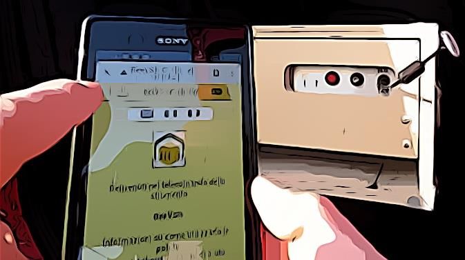
27      SCAN................................................................................................................. 17
28          Scan by QRCode ........................................................................................... 17
29          Scan by List ................................................................................................... 18
30   MAINTENANCE ..................................................................................................... 19
31   GLASS CLEANING .................................................................................................. 19
32   TROUBLESHOOTING ............................................................................................. 20
33   TECHNICAL ASSISTANCE ....................................................................................... 22
34

                                                                 3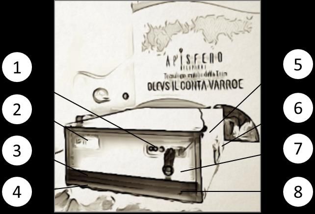
35   OVERVIEW

36
37                 Figure 1 Example of use in the field of the Bee Varroa Scanner

38   The Bee Varroa Scanner, or BeeVS®, is a scanner that allows you to photograph
39   sticky boards placed at the bottom of hives, recognizing and counting Varroa
40   destructor mites. The scanner is remotely controlled through the use of a
41   smartphone or computer connected to the instrument via a Wi-Fi wireless
42   connection.
43    The BeeVS was designed and implemented
44   by Apisfero A.P.S. ®, a social promotion
45   association that deals with environmental
46   research, a research body accredited by the
47   MIUR (Italian Ministry of Education, Figure 2 Creative Common Certificate
48   University and Research).
49   The BeeVS project is protected by a Creative Common certificate.
50   The names BeeVS and Apisfero are registered trademarks of the Turin Chamber
51   of Commerce, all rights of use are reserved.
52   This manual indicates the instructions for safe use and maintenance of the Bee
53   Varroa Scanner. This manual must be read before using the BeeVS because it

                                                 4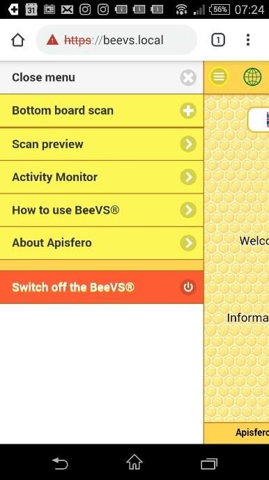
54   presents methodological indications and clarifies some fundamental aspects to
55   avoid erroneous Varroa counts.

56   IMPORTANT NOTICE
57   Safety
58   Use only connections / accessories specified by the manufacturer and supplied
59   with the instrument.
60   Use only the power systems listed in the user manual.
61   Do not expose the product to drips or splashes.
62   Do not place potentially dangerous objects on the product (for example, objects
63   containing liquids or lighted candles).
64   Keep them away from children.
65   Disconnect the instrument in the manner indicated by the manual to avoid
66   damage to the internal computer memories.
67   Warnings
68   Do not remove the instrument coating for any reason.
69   Never lubricate any part of the product.
70   Do not introduce magnets inside the instrument.
71   Keep the product away from direct sunlight, flames or heat.
72   Make sure the power cord does not interfere with operation.

                                           5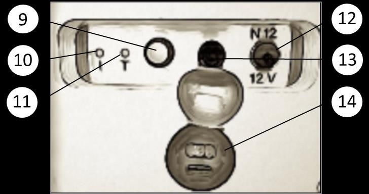
73   Notice
 74   Any modification or intervention on this device that is not expressly permitted by
 75   Apisfero A.P.S. may invalidate the user's right to use the appliance.

 76   Liability Exclusion
 77   The manufacturer is not responsible in case of failure to connect the instrument
 78   to the Wi-Fi network due to external anomalies not depending on the device.

 79   Environmental Compliance
 80   it is important to respect the environment to prevent pollution and possible
 81   damage to the health of the ecosystem.
 82   For each BeeVS made, a tree is planted to compensate for the ecological footprint
 83   of this instrument.
 84   The device is composed of materials that can be recycled and reused as long as
 85   the disassembly is carried out by specialized companies.
 86   The materials for the construction of the BeeVS were possibly found at zero-mile.
 87   This tool has been designed and manufactured with high quality materials and
 88   components, which can be recycled and reused.
 89   The use of any unnecessary packaging has been avoided. Furthermore, we tried
 90   to simplify the recycling process, using the minimum of the possible material for
 91   the packaging.
 92   Keep packaging materials for the return of the instrument that remains the
 93   property of Apisfero A.P.S.
 94   When the symbol of the waste bin with a cross is on a product, this means that it
 95   is subject to the European Directive 2002/96/EC.
 96   These specifications are subject to change without notice. Apisfero A.P.S. reserves
 97   the right to modify the products without the obligation to implement these
 98   changes even in previous versions.

 99   Compliance
100   This product complies with the radio interference requirements of the European
101   Community. Wireless features are authorized for indoor and outdoor use.

                                              6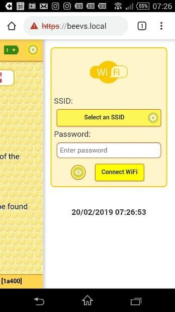
102   A copy of the EC Declaration of Conformity and the technical file that contains it,
103   the registration to the WEEE and the AEE disposal consortium are available at the
104   following web address: https://www.apisfero.org/ce

105   TECHNICAL SPECS
106   Manufacturer: Apisfero A.P.S. Via Leopoldo Lanfranco 19, 10137 Torino
107   Dimensions: Lenght: 640 mm, Width: 480 mm, Height: 200 mm.
108   Weight: 15 kg
109   Power supply: 12 Vcc, 1.8 Amp
110   Fuse: 2 Amp
111   USB port: 2.1 Amp
112   CE Marking
113
114
115
116                                           Figure 3 Example of CE marking on the BeeVS

117

118   OPERATING CONDITIONS
119   In order to use properly the Bee Varroa Scanner, the following operating
120   conditions must be satisfied:
121    a) The 12Vd low voltage power supply of the device allows its use in the
122       laboratory with the power supply and in the apiary with the mobility kit that
123       is described in the instrument's equipment;
124    b) Ambient temperature must be in range -10 to + 50 ° C;
125    c) The BeeVS must be placed on the lower side (Figure 4). A slight tilt is not a
126       problem as long as the scanned tray remains in place during scanning;
127    d) The basic equipment includes a 220 V power supply, the 12 volt mobility
128       equipment is on request;
129    e) Wi-Fi connectivity for internet access and access to the BeeVS from the
130       remote control;
131    f) USB port for powering a mobile device whose load must not exceed 2 Amp;
132    g) he BeeVS has a focusing tolerance of 5 mm, so the tray that is placed inside
133       it must not exceed this thickness.
134    h) Average scan duration: 30 Sec.

                                              7
135   SUPPLIED MATERIAL
136   The Bee Varroa Scanner comes with a bag containing the following supplied
137   material:
138       • user and maintenance manual;
139       • 220 V power cable (3 m long);
140       • glass cleaning cloth;
141       • brush for cleaning the bottom of the ionstrument;
142       • only on request - 12 V DC power cable with cigarette lighter for cars
143           (length 30 cm);
144       • only on request - 12 V DC power cable with clamps for the car battery
145           (length 30 cm).

146   NECESSARY EQUIPMENT NOT SUPPLIED
147   To detect varroa mites using the BeeVS, it is necessary to use the following
148   equipment not supplied with the instrument:
149    a) white A3 paper or white adhesive paper, 350 x 450 mm removable and
150       storable if dry;
151    b) tray (eg, the lower one of the hive) max. 435 x 510 mm (the tray must be flat,
152       neither concave or convex, without folds);
153    c) martphone with OS Android (minimum version 5.x) and Chrome browser;
154    d) For use in the laboratory as an alternative to the smartphone, it is possible
155       to use a Windows 7 PC or higher or Mac equipped with Chrome browser with
156       Wi-Fi connectivity and camera, for remote control functions.

157   DESCRIPTION
158   Details of the instrument
159   The Bee Varroa Scanner consists of a wooden box (Figure 4), with reinforced
160   metal edges and a side handle (6) for transport.

                                              8
161
162                               Figure 4 Details of the instrument

               Control panel                           Magnet to hold power cord

               CE Marking                                                    Handle
                                                      USB socket for mobile device
               Opening and zero point
                                                                         charging
               Left limit marking                                 Right limit marking
163   On the front side there is an opening (3) for the introduction of the tray containing
164   the sheet of white paper (possibly adhesive) with Varroa and other material.
165   Inside the opening, there are two longitudinal lines (4) and (8) and a transverse
166   one, for the positioning of the tray. On the left side, a wooden strip that indicates
167   the zero point of positioning of the tray (angle A, Figura 10)
168   Still on the front side, there is the operating panel (1) and the identification plate
169   of the scanner (2), which shows the CE mark and the QRCode with the address
170   https: //beevs.local, necessary to connect the remote control (smartphone) to the
171   BeeVS via the chrome browser on the smartphone. There is the USB socket (7) for
172   charging mobile devices (Max 2.1 Amp). On the right side of the BeeVS there is a
173   magnet for holding the power cord (5) and the carrying handle (6).

                                                  9
174 Control panel
175 The control panel consists of the power supply connector (12), the protection fuse
176 (13), the red button for powering off the instrument (9), the "I" (10) and "T" (11)
177 LEDs.
178
179 Figure 5 Control panel
Red button for powering off
Power supply 12 Vcc
the instrument
“I” LED (Internet connection) Fuse
USB socket for charging
“T” LED (remote control)
mobile devices
180
181 The "I" LED (10) indicates the Internet connection of the BeeVS for the
182 transmission of the scans.
183 • “I” green: there is an Internet connection;
184 • “I” red: absence of connection to the network;
185 • “I” blue: the strumnento is sending information on the internet, do not
186 turn off the BeeVS in this case;
187 • “I” yellow: the BeeVS is connected to the Internet, there are scans to be
188 sent but the automatic upload is not active (see how to activate the
189 sending of scans on the Internet.
190 The “T” LED (11) indicates the connection of the remote control to the BeeVS.
191 • “T” green: presence of the connection between smartphone and BeeVS;
192 • “T” red: absence of connection between smartphone and BeeVS.
10193 LEDs off: indicate that the scanner is off;;
194 Both LEDs flashing red: indicate an anomaly of the cameras, follow the
195 instructions for switching the device off and on again.
196 Both LEDs flashing green: internal BeeVS memory full; connect the device to the
197 Internet by following the BeeVS connection instructions. Thi allow scans to be
198 downloaded to the server, freeing memory on the scanner.
199 Both LEDs flashing yellow: remote firmware update in progress, do not switch off
200 the BeeVS until the operation is complete.
201 At the end of the startup phase, LEDs turn red.
202 At the end of the shutdown, LEDs turn off.
203
T LED
I LED
Desciption (Remote
(Internet)
control)
The remote control is connected to the
- Green
BeeVS
The remote control is NOT connected to the
- Red
BeeVS
The BeeVS is connected to the Internet and
Green -
there are NO scans to send
The BeeVS is connected to the Internet and
Blue -
is sending images to the counting server
The BeeVS is connected to the Internet,
there are scans to be sent but the Yellow -
automatic upload is not active
The BeeVS is NOT connected to the Internet Red -
Flashing: Err01 - General error of cameras
Red Red
malfunction
Flashing: Err02 - The internal memory of the
Green Green
BeeVS is full
Flashing: Firmware update, do not switch
off the BeeVS until the operation is Yellow Yellow
complete
11204 STARTUP AND SHUTDOWN
205 The Bee Varroa Scanner is switched on when the power supply connector is
206 connected and screwed to the power port (12, Figure 5. Make sure to match the
207 two male and female white dots. Wait for the device to start (about 20 seconds)
208 indicated by an acoustic signal and by the red or green leds (10 and 11, Figure 5)
209 and by the sound produce by the movement of the internal cameras.
210 You can select different languages: English, Italian, French, Austrian
211 To switch off the BeeVS you can act in two ways:
212 Recommended shutdown
213 Select the "Switch off the BeeVS" item on the T1 menu (Figure 6) of the remote
214 control and wait for the device to switch off (i.e. when the LEDs go out) before
215 removing the power cable (about 20 seconds).
216 Emergency shutdown
217 Press the red button (9, Figure 5) of the control panel 4 times in rapid succession
218 and wait for the shutdown (i.e. when the LEDs go off) before removing the power
219 cable (about 20 seconds).
220 Warnings: A sudden shutdown may damage the internal memory of the BeeVS.
221 HOW TO CONNECT THE BeeVS TO THE REMOTE
222 CONTROL
223 Once switched on, the BeeVS must be connected to the remote control
224 (SMARTPHONE) via Wi-Fi.
225 First startup
226 The first time you connect a mobile device to the scanner, activate the Wi-Fi
227 recognition on your mobile phone: on the Wi-Fi menu, select BeeVSApXX, insert
228 the password "apisphere" and wait for the connection to appear. Usually one
229 should read the "Connected" status.
12230 Next startups
231 In the absence of other Wi-Fi networks,
232 the mobile device connects T1 T2
233 automatically to BeeVSApXX. In place of
234 'XX' indicate the numeric code of the
235 BeeVS supplied (for example, in Figure 5 T3
236 the code '12' is indicated above the
237 power supply socket). In the presence of
238 other Wi-Fi networks, you need to connect to
239 the BeeVSApXX network: go to the Wi-Fi menu,
240 select BeeVSApXX and wait for it to indicate the
241 presence of the connection. Usually one should
242 read the "Connected" status.
243 Una volta collegato il telecomando al BeeVS,
244 entrare sul browser Chrome e collegarsi al sito
245 https://beevs.local. A questo punto si potrà
246 osservare che il LED “T” diventa verde. Figure 6 Homepage of the remote control
247 Salvare nei preferiti questo indirizzo per poterlo utilizzare le volte successive.
248 The Home page of the Apisphere remote control is displayed and the “I” LED (10,
249 Figure 5) changes from red to green.
13250 HOW TO USE THE REMOTE CONTROL
251 On the remote control, from the Home page you can access two menus (T1, T2
252 Figure 6).
253 LEFT T1 menu
254 It allows you to select the BeeVS control items. The
255 essential ones are listed below (Figure 6, Figure 7):
256 Tray scan, allows to scan in two modes:
257 • Stockwindel scannen, scan with hive
258 selection via QRCode;
259 • List, scan with selection of the hive
260 through the list.
261 Scan preview, launch a scan preview that
262 allows you to visually check the correct
263 functioning of the BeeVS cameras. This
264 modality is recommended before starting an
265 important campaign of scans. The preview does
266 not allow you to save the scan, but only to view
267 it.
268 Activity monitor, opens a submenu that allows to Figure 7 Left T1 menu
269 enable or disable the following functions:
270 • Automatic loading of scans;
271 • Check the operational status of the BeeVS;
272 • View the queued scans (the implementation of this feature in progress).
273 BeeVS Switch off, function to be used for switching off the instrument.
14274 Right T2 menu
275 Allows to select the Wi-Fi network (Figure 6 e Figure 8) to connect the BeeVS to
276 the Internet hotspot (i.e. Wi-Fi modem) as described below.
277 Collegare il BeeVS a Internet
278 Through the T2 menu it is possible to connect the BeeVS to the Internet hotspot
279 (i.e. Wi-Fi modem) through the following modes:
280 First connection
281 Enter or select the SSID (the name of the internet hotspot) and insert the
282 password of the Wi-Fi network and wait for the connection to be established.
283 Next connections
284 Select the SSID (the name of the internet hotspot) of the Wi-Fi network and wait
285 for the connection to be established. The "I" LED turns green.
286 The status of the Internet connection (which it is not essential to perform scans),
287 can be verified by the color of the T3 icon. In Figure 6, the T3 icon is red, indicating
288 a missing Internet connection. The green globe indicates the presence of the
289 Internet connection.
290
291
292 T3
293
294
Figure 9 Active internet connection (T3)
Figure 8 Right T2 menu
15295 HOW TO SCAN
296 PRELIMINARY OPERATIONS
297 Before using the Bee Varroa Scanner, you must first place a white sheet on the
298 bottom of the hive. Then from 1 to 6 days before the scan one needs to:
299
300 1. Provide a sheet of white paper of the appropriate size not exceeding
301 350x450 mm, possibly self-adhesive sheets to prevent the wind from
302 blowing the rose during the removal and also avoid the removal of the
303 varroe by the ants. In case of self-adhesive paper, remember to remove
304 the protective sheet;
305 2. Place the sheet with the adhesive side up on the bottom of the hive;
306 In addition, the following preparatory activities are required before making the
307 scans:
308 3. Create the record of the apiary / hives being counted on the platform
309 https://www.apisferoweb.it;
310 4. Print the QRCode codes of each hive (for scanning via QRCode), or
311 download the list of hives on the remote control for scanning using the
312 smartphone with username and password of www.apisferoweb.it.
313 After the period of stay of the sheet on the bottom of the hive, carry out the
314 following operations:
315 1. record the interval of permanence of the sheet on the bottom of the hive
316 and the date of removal, useful for the subsequent calculations;
317 2. mark the sheet to link it to the name of the hive being counted as
318 previously inserted on the apisferoweb.it site;
319 3. extract the sheet with the whole tray and, proceed with the scanning if
320 you use the scanner in the field or protect the adhesive sheet and put the
321 not sticky side of the previously removed protective sheet upon the
322 Varroa and other material, if you intend proceed with a delayed scan.
16323 SCAN
324 1. Place the BeeVS on a horizontal, vibration-free surface.
325 2. Turn on the scanner, as described in the previuos STARTUP AND SHUTDOWN
326 section (wait for the two LEDs to turn red).
327 3. 3. Connect the remote control (smartphone) to the scanner as described in
328 HOW TO CONNECT THE BeeVS TO THE REMOTE CONTROL
329 4. Insert the tray into the scanner, so that it is inside the longitudinal and
330 transverse lines that can be seen from the opening, taking care to align the
331 left corner of the tray to the zero point (A, Figura 10).
332 5. Select the scan item from the T1 menu and:
333 Scan by QRCode
334 Frame the QR code of
335 the hive and wait for the
336 completion of the scan
337 (approximately 30
338 seconds followed by an
339 acoustic signal).
340 WARNINGS: if the camera
341 automatically selected on the
342 smartphone is not the rear one, so
343 that instead of the QRCode you see
344 your face, then select the button at
345 the bottom of the remote control
346 and select the “Camera x, facing
347 back”
Figura 10 Insert the sheet into BeeVS zero point (A)
17348 Scan by List
349 List scanning is an alternative to scanning via QRCode:
350 List already present on the remote control
351 If the list is already present on the remote control, just enter the
352 password, the same one used on https://www.apisferoweb.it, scroll
353 through the list and select the name of the hive being scanned.
354 List not yet present on the remote control
355 If there is no list on the remote control, connect the BeeVS to the Internet
356 as described in chapter HOW TO CONNECT THE BeeVS TO THE REMOTE
357 CONTROL and identify yourself with the same credentials used on
358 https://www.apisferoweb.it in order to download or update the list of
359 hives.
360 WARNINGS: before performing a high number of scans, it is strongly
361 recommended to run the Scan preview (Figure 7) to check the correct
362 functioning of the scanner cameras.
363 The scan takes about 30 seconds. In this time frame, do not move the
364 BeeVS or move the sheet inside the BeeVS. The progress of the scan is
365 indicated on the remote control, by a percentage progression bar and its
366 completion by an acoustic signal.
367
368 6. After scanning, remove the tray and continue with a new scan, taking care
369 to match the scan to the correct hive, until the session is finished.
370 7. Make another scan until your job session of scanning.
371 8. Turn off the scanner as described in STARTUP AND SHUTDOWN (wait for
372 the two LEDs to switch off).
373 WARNINGS: proceed with the shutdown only if the instrument has
374 completed the uploading of the scans on Internet (LED 10 blue, Figure 5),
375 otherwise wait until the LED go back to green.
376 9. Disconnect the power supply only if the LEDs are off.
18377 MAINTENANCE
378 In addition to periodically cleaning the bottom of the instrument with the brush
379 supplied, and the glass according to the indications of the section GLASS
380 CLEANING, the Bee Varroa Scanner does not require maintenance if the following
381 precautions are taken:
382 • It is kept in a dry and clean place.
383 • It must not be subjected to strong vibrations, shocks or jolts.
384 • It should not be left for prolonged periods of time in environments that
385 are too hot or too cold or humid.
386 • Prevent foreign bodies from entering the box through the opening.
387 The only maintenance that may be required is:
388 1. replacing the fuse when the BeeVS does not turn on when the power
389 supply is connected.
390 To replace the fuse, operate as follows:
391 • On the control panel, unscrew the fuse cap (13, Figure 5).
392 • Remove the fuse.
393 • Insert the new fuse of same amperage in its housing.
394 • Fully tighten the fuse cap.
395 2. Cleaning the glass with the supplied cloth (GLASS CLEANING).
396 WARNINGS: Except for the purpose of cleaning the glass lower face, for no other
397 reason it is allowed to open the front panel of the BeeVS, unless written
398 authorization is provided by Apisfero A.P.S.
399 GLASS CLEANING
400 It is necessary a periodic cleaning of the lower face of the glass which protect the
401 electronic components and cameras of the scanner.
402 To proceed with cleaning, place the BeeVS on the floor with the opening upwards,
403 unscrew the four screws of the front panel, remove the front panel and turn it
404 anticlockwise slightly, without pulling or tugging it. Then, pass the supplied cloth
405 slightly moistened and clean the glass on the underside. Make sure the glass is
406 dry and clean before placing it on the housing with the side seals facing down.
407 Reassemble the front panel following the disassembly operations in reverse.
19408 TROUBLESHOOTING
409 The following warings can be displayed on the remote control during operations.
410 Before contacting assistance, follow the instructions in the "What to do" column
411 of the next table:
Warning What to do
Wrong hive code! The hive code has not been recognized:
verify that it is correct and try again
Error reading hive code! As above
Scan error Resend the scan and mark the scan to be
deleted later
Login failed Unrecognized user: try again
There are no beehives Create at least one apiary and beehive on
www.apisferoweb.it site, in order to use
the BeeVS
The user has no apiaries Create at least one apiary and beehive on
www.apisferoweb.it site, in order to use
the BeeVS
Carriage locked The internal trolley supporting cameras is
locked: turn off the BeeVS and try to
switch it on again.
Cameras error One of the cameras experienced an error:
switch the BeeVS off and on again
Motor error The electric motor experienced an error:
switch the BeeVS off and on again
Scanning error, shut down and start Follow the instructions to start up the
up the BeeVS BeeVS.
20The battery is low, replace it as soon Low external power battery level: replace
as possible the power source
Device not compatible, please use It is not possible to use the connected
beehive list smartphone model to perform the scans:
perform the scans by selecting from the
list, using the same mobile device
BeeVS not operative, memory is full Memory full, you have reached the limit
of 2000 scans never downloaded: connect
the BeeVS to the Internet for uploading
data and freeing the memory
Camera error One of the cameras experienced an error:
switch the BeeVS off and on again
BeeVS is disabled, please contact
Contact support
Apisfero admin
WiFi is connected but internet is not Internet connectivity problems not
available dependent on the BeeVS
Scanner disabled You must be enabled to use the scanner:
contact support
Unknow user Unrecognized user: try again
Users blocked User blocked by the system: contact
support
412
21413 TECHNICAL ASSISTANCE
414 For technical assistance, contact:
415 Apisfero A.P.S.
416 Via Leopoldo Lanfranco, 19
417 10137 Torino (Italy)
418 tel.: +39 3317923097
419 info@apisfero.org
420
421 We recommend not print hard
422 copies of this manual to avoid
423 contributing to deforestation
424
22You can also read