ReadySwitch 400 Amp Transfer Switch and Inlet Panel Installation Instructions & User Manual - LEX Products
←
→
Page content transcription
If your browser does not render page correctly, please read the page content below
TYPE 3R Rainproof

ReadySwitch                                        ™

400 Amp Transfer Switch and
Inlet Panel
Installation Instructions &
User Manual

• A cost effective way to prepare your
  business facility for a power outage.
• cULus 1008 listed to ensure safety
  and reliability.
• U.S. Patent Mechanical Interlock for
  safe connection
• Utility & Generator disconnects
• Hinged door with key lock entry
• Suitable for use as Service
  Equipment
  – (US Only)

                                                       LM-RS400 Rev. 003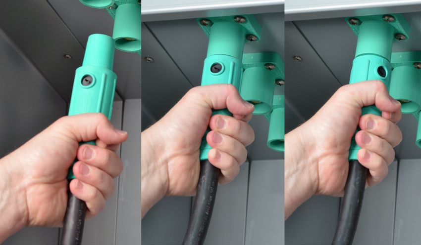
PowerGATE® ReadySwitch™

Contents                                                        Important:
2    Contents                                                   This manual contains information critical to the proper
                                                                installation and operation of the Lex Products PowerGATE®
3    Prior to Installation                                      ReadySwitch™ Panel. Be certain to read and understand all
3    Shipment: Unpacking and Inspection                         instructions prior to installation and operation.
4    Product Features                                           Note: This manual is furnished exclusively to support installation
                                                                and operation of the Lex Products PowerGATE® ReadySwitch™
5    Installation                                               Panel. All concepts and ideas are the sole property of Lex
7    Set-up                                                     Products and are not to be duplicated or utilized in any manner
8    Disconnecting Circuits                                     without written permission.
9    Limited Warranty
9    Maintenance
9    Technical Support

Appendices
10   Appendix A - Pre-Operation and Maintenance Checklist
10   Appendix B - Parts Dimensions
10   Appendix C - Represented Model Numbers and Ratings
10   Appendix D - Labels for Replacement - Parts List
11   Appendix E - Warning Location
12   Appendix F - Specifications

2     Contact
      Contact Lex
              Lex Products:
                  Products: 800.643.4460
                            800.643.4460 info@lexproducts.com
                                         info@lexproducts.com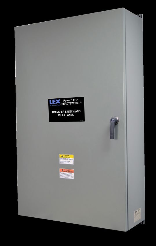
PowerGATE® ReadySwitch™

Prior to Installation: Site Preparation                           Shipment: Unpacking and Inspection
Prepare installation site according to local codes.               – While keylock protection is provided, access by unauthorized
The PowerGATE® ReadySwitch™ is to be secured to a building          personnel and vandals should be taken into consideration
using appropriate 3/8“ fasteners (See Figure 1).                    when locating this device.

The surface where the PowerGATE® ReadySwitch™ is to be            NOTE: Be careful in the use of sharp object when cutting
secured must be capable of supporting the weight of the cabinet   packaging as scratching of outer coating may result in rusting.
as well as the cables attached to it.                             Perform a visual inspection to ensure the door and handles are in
The following should be taken into consideration when locating    functioning condition and that the panel integrity is intact.
the PowerGATE® ReadySwitch™:
                                                                  Determining Your Part Number
– Identify and meet local codes and local Authority Having
  Jurisdiction (AHJ)                                              Review Appendix F to verify part number, rating voltage, and
                                                                  amperage
– The PowerGATE® ReadySwitch™ is designed for exterior
                                                                  Figure 1: 400 AMP
  operation ONLY
– To prevent carbon monoxide poisoning from improperly
  ventilated generator emissions, the PowerGATE®
  ReadySwitch™ must be mounted outdoors only. The
  mounting location is to be carefully selected to allow
  convenient connection to a generator and located a suitable
  distance away from any building openings or HVAC inlets.
– Proper clearance must be allowed in front of the
  PowerGATE® ReadySwitch™ to allow for opening of access
  doors and attachment of externally connected cables. This
  distance should be no less than six (6) feet from the face of
  the panel.

                                                                                 Rear view with mounting holes

                                                                               Contact Lex Products: 800.643.4460 info@lexproducts.com   3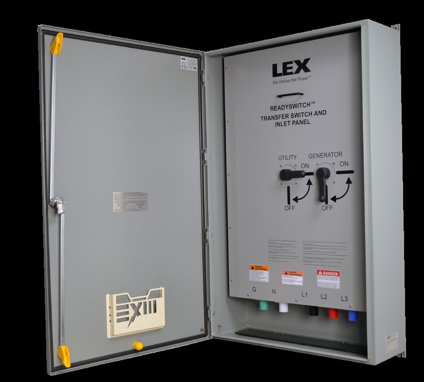
PowerGATE® ReadySwitch™

Product Features
                             Figure 2 Image - Door Open

                                                                                                                               Ample contractor
                                                                                                                               wiring room to
                                                                                                                               accommodate wire
                                                                                                                               bend radii
          Seamless gasket
    provides water & dust                                                                                                      Patent Pending
                tight seal                                                                                                     Interlock

                                                                                                                               Clear identified handle
                                                                                                                               indicates position of
                                                                                                                               the switch

                                                                                                                               Industry standard
                                                                                                                               Cam-type connections
                                                                                                                               save crucial time in
                                                                                                                               emergency situations

Figure 3 Image - Door Closed                                                          Figure 4 Image - Bottom View

                                                                                      Individual cable entry holes restrict   Low profile enclosure is only
                                                              Key lock entry              access, reducing cable theft            11 1/4 inches deep
                                                              prevents unauthorized
                                                              access and operation

–  Enclosure is cULus Listed Type 3R Rainproof*
–  Keyed entry prevents unauthorized access and operation
–  Cables drape straight down
–  Dead-front panel prevents accidental contact with wiring
   chamber
* Any conduit penetrating the bottom must extend to the
  horizontal barrier
4           Contact Lex Products: 800.643.4460 info@lexproducts.com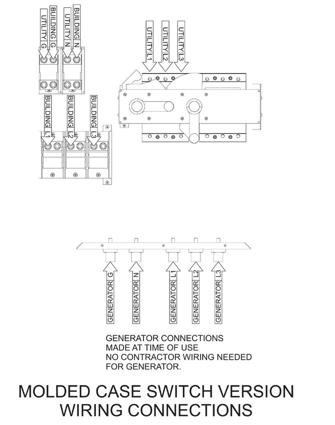
PowerGATE® ReadySwitch™

Installation                                                               Figure 5

The installation of the PowerGATE® ReadySwitch™ should
be carried out by qualified personnel in accordance with local
electrical codes.
Step 1: Fasten the PowerGATE® ReadySwitch™ to secure
location
NOTE: The PowerGATE® ReadySwitch™ weighs 252 lbs.
without attached cables.
1. The panel should be located so there is adequate room for
   the externally connected cables to hang below the panel
   A. Typically allow a minimum of 36” clearance from                                      Front view with hinged cover
      the bottom of the panel to finished ground level                                               removed
2. Installation must be level and plumb to allow for proper                Figure 5A
   drainage from PowerGATE® ReadySwitch™ weep holes
3. Fastening onto an external wall using 3/8” fasteners must
   be completed prior to proceeding with any terminations (See
   Figure 1 for hole spacing)
Step 2: Installing the Conduit
NOTE: Conduit to enter through top or right/left side (No bottom
feed -See Figure 5B)
NOTE: To maintain outdoor rating compliance for the enclosure,
proper sealing procedures must be followed. This is to include,
but not limited to, the use of proper gaskets.
NOTE: In order to prevent enclosure damage and to attain the                               Front view with dead-front
                                                                                                 panel removed
enclosure requirements, the conduit must be aligned to prevent
unnecessary stress on the enclosure walls.                         Figure 5B
1. Open up door to expose dead front panel
2. Unfasten the dead front panel by removing the hardware
   securing it (See Figure 5 and 5A)                                                          Front view with dead front
3. Conduit to be sized according to cabling rating                                                  panel removed

   A. 400 Amp cable range #6-500MCM
4. It is recommended that a knockout punch be used to cut hole
   for conduit
   A. Place the punch on the inside of the enclosure and draw
        the punch through to the die on the outside
5. Vacuum entire upper chamber to ensure no shavings are left
   behind

                                                                                       Front view with hinged cover removed

                                                                                Contact Lex Products: 800.643.4460 info@lexproducts.com   5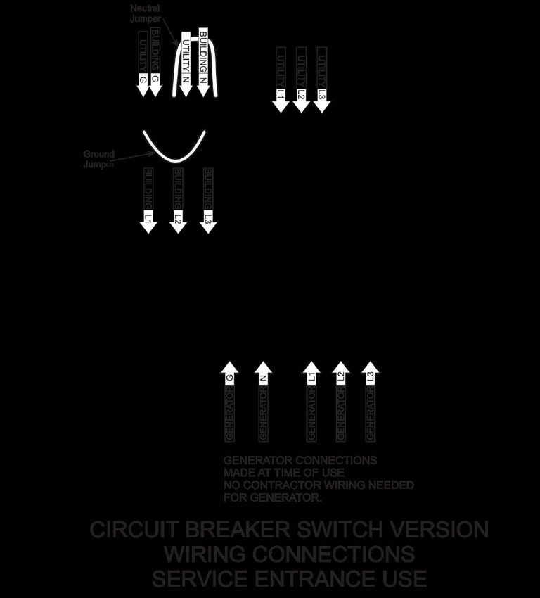
PowerGATE® ReadySwitch™

Figure 6                                                             Figure 6A

                                          Figure 6B

6          Contact Lex Products: 800.643.4460 info@lexproducts.com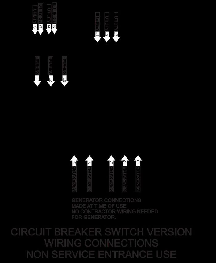
PowerGATE® ReadySwitch™
Installation – Initial Setup - Main Power Installation – Initial Setup - Main Power (continued
Step 1: Wiring the Main Terminals Step 2: Determine Phase Rotation
WARNING The following information will be needed when connecting a
generator:
Ensure circuit breakers are OFF and the transfer switch is
locked out from utility power prior to connection. 1. Determine phase rotation of the utility power
A. Connect a phase rotation meter to a three phase power
Failure to install transfer switch will create the potential
source in the building and record whether the building is
for the generator to energize utility lines and endanger
wired clockwise or counter-clockwise
utility personnel. Conversely, utility lines may energize
the PowerGATE® ReadySwitch™ and endanger generator 2. Apply the provided label (Figure 7) to the inside of the
PowerGATE® ReadySwitch™ on the inside of the cam
personnel.
The PowerGATE® ReadySwitch™ is for the connection to a
DANGER connection chamber door. (Figure 8)
main panel of a structure, with an option HIGH to switchVOLTAGE to backup
Figure 7
generator via a CAM-Type connection, such that KEEP the inletsOUTare
only energized from the generator.
HAUTE TENSION
LBL-PGIP-D1
NE
1. Pull the cables to the PowerGATE® ReadySwitch™ PAS TOUCHER
3Ø Power
2. First, strip and install the ground cable to the ground terminal 3Ø Power
LBL-PGIP-ROTATION
Counter
DANGER
Clockwise
block Clockwise
A. NOTE: See Figure 5A Do not start the generator until all connectors are connected
or made to be inaccessible. Any terminal may be energized
3. Tighten terminal screws to 375 lb.-in.
when any torque eachDe-energize cables at the
cable is connected.
generator prior to connecting or removing any connectors
Apply 1 to inside door of
Input Panel Connection Chamber
A. NOTE: See Figure 9 Ne pas mettre la génératrice en marche avant que tous les
P/N: LBL-PGIP-ROTATION
connecteurs soient connectés ou rendus inaccessibles.
4. If metallic conduit is used, connect
câbleground
est raccordé.wire from ground
N’importe quelle borne peut être mise sous tension si un
LBL-PGIP-D2
Débrancher les câbles à la génératrice
avant de brancher ou de débrancher les connecteurs Figure 7A
bushing on conduit to the ground connection point in the
bottom left quadrant of the panel
WARNING
A. Ground conductor must be a minimum of 2 AWG
AVERTISSEMENT
B. NOTE: Conduit shall NOT be relied upon
Risk of Electric Shockto provide
Plug connection should be in the following order:
P/N: LBL-SERVICEDIS
grounding protection to tap box
1) Equipment grounding conductor connectors,
2) Grounded circuit conductor connectors, and
3) Ungrounded conductor connectors. (Label only applicable for Service Entrance rated version of ReadySwitch)
5. Continue to connect the neutral wire to
Disconnectionthe ground
should terminal
be in the reverse
Risque de choc électrique
order
block. (Service Entrance rated models ONLY)
Le raccordement devrait être effectué dans l’ordre qui suit:
1) Conducteur de mise à la terre de l’appareillage Figure 8
LBL-PGIP-W1
2) Conducteur du circuit mis à la terre
6. Verify the 3 phases of the service3)Laentrance
3) Conducteurs non mis à la terre
mise hors tension doit se faire dans l’ordre inverse
WARNING
Three phase power systems consist of three phase or hot
conductors that are shifted by 120 degrees. Three phase
A
loads such as motors may only work properly if the phases
are connected in the correct order. Some motors may work
B C
C
LBL-A LBL-B LBL-C
when connected improperly, but will operate backwards.
N
Utility power and electrical generators may be wired either in
a clockwise or counter-clockwise order. It is important that
LBL-N
G LBL-G
any generator connected to the PowerGATE® ReadySwitch™
is connected in the same rotation (clockwise or counter-
clockwise) as the utility power.
7. Connect the 3 phases of the switch here:
Transfer Switch Accessory
TYPE 3R
RAINPROOF
Model Place rotation label here
A. MAIN TERMINAL
Rating
B. BUILDING TERMINAL
LBL-PGIP
S/N
8. Replace dead front panel and secure using hardware
Made in USA www.lexproducts.com 1-800-643-4460
Contact Lex Products: 800.643.4460 info@lexproducts.com 7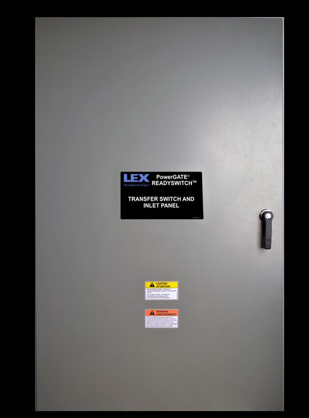
PowerGATE® ReadySwitch™
Installation – Initial Setup - Main Power (continued) Connecting A Portable Generator (continued
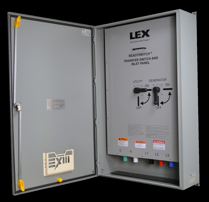
Step 3: Complete a Safety Test Step 3: Making Cam Connections
Do not attempt to use the PowerGATE® ReadySwitch™ prior 1. Open the front door of the PowerGATE® ReadySwitch™
to installation and completing the Pre-Operation and Operation 2. Ensure that the vermin door is un-obstructed and that the
Checklist under Appendix A. cable can flow freely through cable entry holes
Step 4: Completing Set Up 3. Complete the Ground (green) connections first by feeding
the cable through the appropriate port, beginning with the
1. Close utility and re-energize system closest from the door to the left.
2. After ensuring system power, close the door of the Proper connection (See Figure 9):
PowerGATE® ReadySwitch™
A. Grasp connector jacket and firmly insert Cam connector
3. Lock the door, marking the keys as appropriate into Cam plug
B. Push on connector jacket until connector fully seats in
Connecting A Portable Generator plug
C. Rotate connector jacket counterclockwise until it stops.
Step 1: Review Pre-Operation Checklist under Appendix A
(see Figure 9)
prior to operation (page 10)
4. Complete ALL Neutral connections prior to proceeding
WARNING 5. Complete the hot connections by feeding the cable through
the appropriate port and connect to the CAM-Type connector
– DO NOT ATTEMPT CONNECTION WHILE CIRCUITS ARE
LIVE A. (BLACK/BROWN- PHASE A- LINE 1, RED/ORANGE-
– Do not use cables if they appear frayed PHASE B- LINE 2, BLUE/YELLOW- PHASE C- LINE 3
– Do not use cable if connectors or plug do not seat properly B. Utilize the notes concerning phase rotation below
– Do not use cables if any copper cabling is exposed C. Should the phase rotation of the generator (as determined
– To limit risk of shock, disable generator automatic start to in Step 2.3. above) and utility power (label found on
prevent unintended starting the inside of the door for the Cam connection chamber)
match, connect the Hots as follows:
Step 2: Determining phase rotation of generator Generator Hot PowerGATE® ReadySwitch™ Hot
1. Disconnect generator from all loads if needed A A
2. Connect a phase rotation meter to the output phases of the B B
generator C C
3. Record generator phase rotation (clockwise or counter-
clockwise) D. Should the phase rotation of the generator (as determined
in Step 2.3. above) and utility power (label found on the
Figure 9 inside of the door for the Cam connection chamber) NOT
match, connect the Hots as follows:
Generator Hot PowerGATE® ReadySwitch™ Hot
A B
B A
C C
6. Complete ALL Phase connections prior to proceeding
7. Make sure all connections are right and secure
Step 3: Close and secure chamber door, allowing cables to
exit through cable ports at bottom
8 Contact Lex Products: 800.643.4460 info@lexproducts.com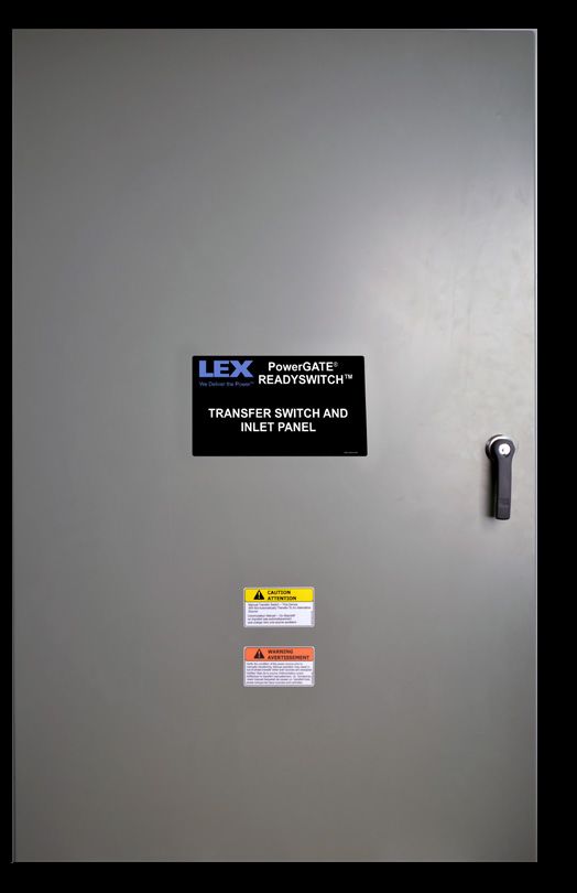
PowerGATE® ReadySwitch™

Operation                                                          Disconnecting a Portable Generator
                                                                   (continued)
        WARNING
                                                                   5. Disconnect the Neutral (white) connection
  Power MUST BE supplied from a single generator
                                                                   6. Disconnect the Ground (green) connection
Switching                                                          Step 4: Close and lock front door of the PowerGATE®
                                                                   ReadySwitch™
1. To switch from MAIN power to BACKUP power:
   A. Portable generator must be connected prior to this step      Limited Warranty
      (see step 3.5 above)
                                                                   When this PowerGATE® ReadySwitch™ is installed and
   B. Start generator per manufacturer instructions
                                                                   operated according to the manual’s instructions Lex Products
   C. Close main breaker on the generator                          will repair or replace any of its mechanical or electrical parts
   D. Open the front door of the PowerGATE® ReadySwitch™           if they are found to be defective in material or workmanship
                                                                   within one year of the purchase date.
   E. Turn the UTILITY BREAKER to OFF
   F. Turn backup breaker to ON                                    Maintenance
  G. Close and lock chamber door, ensuring that all cables exit
                                                                   The PowerGATE® ReadySwitch™ will require periodic
      through the entry holes at the bottom
                                                                   maintenance. Lex Products recommends annual inspections
2. To switch from BACKUP power to MAIN power                       to keep the panel in safe operating condition. Lex Products
   A. Open the front door of the PowerGATE® ReadySwitch™           recommends that the Pre-Operation and Operation Checklist
                                                                   under Appendix A serve as a basis for annual inspection.
   B. Turn the backup breaker to OFF
   C. Turn the MAIN breaker to ON                                  Technical Support
   D. Close and lock chamber door, ensuring that all cables exit
                                                                   Lex Products technical services are available to assist in
      through the cable entry holes at the bottom
                                                                   resolving issues by calling 800.643.4460 or emailing info@
3. Open the main breaker on the generator                          lexproducts.com. For any other information, please call Lex
4. Stop and turn off generator per manufacturer instructions       Products at 800.643.4460 or e-mail info@lexproducts.com.

       WARNING                                                     Figure 10 - Torque Chart ReadySwitch™ Installation
  DO NOT ATTEMPT TO DISCONNECT GENERATOR WHILE                               Location                                 400A
  CIRCUITS ARE LIVE.
                                                                     CB OR SWITCH LUG KIT                       380 IN-LB (43 N-M)
Disconnecting a Portable Generator                                   TERMINAL BLOCKS                            375 IN-LB (42 N-M)
1. Open the front door of the PowerGATE® ReadySwitch™              Figure 11
   A. To limit the risk of shock, disable generator automatic
       start to prevent unintended starting.
2. Disconnect the Phase (hot) connections, beginning with the
   furthest to the right
Proper disconnection (See Figure 9):
   A. Grasp connector jacket firmly and rotate cam connector
       clockwise until it stops
   B. Firmly pull on connector until it separates from the plug
   C. Set aside
4. Continue with ALL Phase (hot) connections
5. Complete disconnect of ALL hot connections prior to
    proceeding
                                                                                 Contact Lex Products: 800.643.4460 info@lexproducts.com   9
PowerGATE® ReadySwitch™

Appendix A                                                         Appendix C
Pre-Operation & Operation Checklist                                Represented Models and Wire Range for ReadySwitch
1. Visual inspection of enclosure
   – Ensure the PowerGATE ReadySwitch is firmly secured to         Part Number                                      Wire Range
      the building                                                 PIPM0400-C-C-AJ-GRXEE                            #6-500MCM
   – Review conduit connection for signs of leakage                PIPM0400-C-C-AJ-GOXEE                            #6-500MCM
   – Ensure enclosure is intact with no signs of cracking          PIPM0400-C-C-AJ-GBXEE                            #6-500MCM
2. Open the front door of the PowerGATE ReadySwitch                PIPM0400-S-S-AJ-GRXFF                            #6-500MCM
   – Ensure the chamber is dry and free of debris                  PIPM0400-S-S-AJ-GOXFF                            #6-500MCM
   – Ensure the vermin door is un-obstructed and that cable        PIPM0400-S-S-AJ-GBXFF                            #6-500MCM
      can flow freely through cable entry holes
   – Ensure that gaskets are pliable and no cracking exists        Appendix D
   – Ensure that door hinges are secure and lubricated
   – Ensure that hasps are intact and operational                  Labels for Replacement - Parts List
3. Inspect all portable cables
   – Do not use cables if they appear frayed
   – Do not use cable if connectors or plug do not seat
      properly                                                                                             WARNING
   – Do not use cables if any copper wiring is exposed                                                     AVERTISSEMENT
4. Lex Products technical services are available to assist in                          Verify the condition of the power source prior to
   resolving issues. If you have any questions or need technical                       manually transferring. Manual operation may result in
                                                                                       out-of-phase transfer when both sources are energized.
   advice or suggestions regarding this product, please contact                        Vérifiez l'état de la source d'alimentation avant

                                                                                                                                                      10519-2-026 rev 000
                                                                                       d'effectuer le transfert manuellement. Un fonctionne-
   Lex Products at 800.643.4460 or e-mail info@LexProducts.                            -ment manuel risquerait de causer un transfert hors
   com                                                                                 phase lorsque les deux sources sont activées.

                                                                                                        p/n: – 10519-2-026
Appendix B                                                                                                       4.00"
Initial Setup Safety Checklist

                                                                                                       DANGER
1. Ensure that all load terminals are securely fastened and that
    the set screws are set at 375lb.-in torque each
2. Ensure electrical connections are intact with no signs of                           Do not start the generator until all connectors are connected
    corrosion or cracking                                                              or made to be inaccessible. Any terminal may be energized
                                                                        2.75"

                                                                                       when any cable is connected. De-energize cables at the
                                                                                       generator prior to connecting or removing any connectors
3. Review all safety labels and ensure that they are present and
    legible. See Appendix E for label nomenclature and location.                       Ne pas mettre la génératrice en marche avant que tous les
                                                                                       connecteurs soient connectés ou rendus inaccessibles.
                                                                                       N’importe quelle borne peut être mise sous tension si un
    Replace as needed
                                                                                                                                                              LBL-PGIP-D2

                                                                                       câble est raccordé. Débrancher les câbles à la génératrice
                                                                                       avant de brancher ou de débrancher les connecteurs
4. Ensure Phase rotation is correct
    – Verify Phase A of MAIN is PHASE A as labeled on the                                               p/n: – LBL-PGIP-D2
        terminals of the input                                                                                  4.00"
                                                                     R 0.125
    – Verify Phase B of MAIN is PHASE A as labeled on the
        terminals of the input                                                                         WARNING
    – Verify Phase C of MAIN is PHASE A as labeled on the                                              AVERTISSEMENT
                                                                           Lex P/N:Risk
                                                                                     LBL-PGIP-D2
        terminals of the input                                             Revision: NS
                                                                                   Plug
                                                                                        of Electric Shock
                                                                                        connection should be in the following order:
                                                                        2.75"

                                                                                    1) Equipment grounding conductor connectors,
    – Verify Phase A of BUILDING is PHASE A as labeled on                  Red color
                                                                                    2) Grounded circuit conductor connectors, and
                                                                                       to be ANSI
                                                                                    3) Ungrounded      Z535.4
                                                                                                   conductor       ‘Danger’ Red
                                                                                                              connectors.
        the terminals of input                                                      Disconnection should be in the reverse order
                                                                                    Risque de choc électrique
                                                                           MaterialsLeto  be the samedevraitor
                                                                                                             êtresimilar
                                                                                                                  effectué to  LBL-CS400
    – Verify Phase B of BUILDING is PHASE A as labeled on the                          raccordement                         dans l’ordre qui suit:
                                                                                    1) Conducteur de mise à la terre de l’appareillage
                                                                                                                                                     LBL-PGIP-W1

        terminals of the input                                                      2) Conducteur du circuit mis à la terre
                                                                                    3) 3) Conducteurs non mis à la terre
                                                                                    La mise hors tension doit se faire dans l’ordre inverse
    – Verify Phase C of BUILDING is PHASE A as labeled on the
        terminals of the input                                                                         p/n: – LBL-PGIP-W1

                                                                    R 0.125
10     Contact Lex Products: 800.643.4460 info@lexproducts.com
PowerGATE® ReadySwitch™
Appendix D (continued)
SHORT-CIRCUIT WITHSTAND AND CLOSING RATINGS
COURANTS NOMINAUX DE RÉSISTANCE AU COURT-CIRCUIT ET DE FERMETURE DE CIRCUIT
When protected by a circuit breaker, this transfer switch is suitable for use in a circuit capable of
BUILDING (LOAD) LBL-RDYSW-BUILDING 000
delivering the short-circuit current for the maximum time duration and voltage marked below.
S’il est protégé par un disjoncteur, ce commutateur convient aux circuits capables d’acheminer
un courant de court-circuit pendant la durée et à la tension maximales indiquées plus bas..
L1 L2 L3
The circuit breaker must include an instantaneous trip response and shall not include a short-time
trip response.
Le disjoncteur doit être à déclenchement instantané sans déclenchement rapide.
p/n: LBL-RDYSW-BUILDING
The maximum clearing time of the instantaneous trip response must be equal to or less than the time
duration shown for the marked short-circuit current.
Le temps de coupure maximal pour le déclenchement instantané doit être égal ou inférieur à la durée
indiquée pour le courant de court-circuit.
SHORT-CIRCUIT CURRENT VOLTAGE MAXIMUM TIME DURATION LBL-RDYSW-GGN 000
COURANT DE COURT-CIRCUIT TENSION MAXIMUM LE TEMPS DURÉE
35,000 A RMS
25,000 A RMS
480V AC
600V AC
0.050 S
0.050 S GG N
This transfer switch does not include short-time current ratings. 400A maximum overcurrent devicew
Ce commutateur n’est pas évalué pour les courants nominaux de courte durée. p/n: – LBL-RDYSW-GGN
400A maximum le dispositif de protection LBL-RDYSW-SCCR-SW 000
p/n: – LBL-RDYSW-SCCR-SW
For Service Entrance Rated Version please use UTILITY (LINE)
p/n: – 10519-2-023
Part Number: LBL-RDYSW-SCCR-SW
LBL-RDYSW-UTILITY 000
L1 L2 L3
p/n: – LBL-RDWSW-UTILITY
CAUTION 3/16”
ATTENTION UTILITY: 43 N-M, 380 IN-LBs
8 mm
Manual Transfer Switch – This Device
BUILDING, N, G: 42 N-M, 375 IN-LBs
Will Not Automatically Transfer To An Alternative
Source
Cu – Al
10519-2-024 rev 000
Commutateur Manuel – Ce dispositif
ne transfert pas automatiquement
une charge vers une source auxiliaire LBL-RDYSW-TSS 000
75°C / 90°C
p/n: – LBL-RDYSW-TSS
p/n: – 10519-2-024
Appendix E
Warning Locations
10519-2-023
READYSWITCH TM
TRANSFER SWITCH AND
INLET PANEL
UTILITY GENERATOR
READYSWITCH TM
ON ON
TRANSFER SWITCH AND
INLET PANEL
10519-2-023 rev 000
OFF OFF
T Type 3R une fois installé avec conduit ou raccords de conduits à l'épreuve de la pluie (homologation UL)
Not for indoor use Ne pas utiliser à l’intérieur
Continuous load current not to exceed 80 percent of switch rating Le courant de charge continu ne doit pas dépasser de 80 pourcent le courant nominal du commutateu r
Suitable only for use with generators that do not have the neutral bonded Approprié seulement pour utilisation avec des générateurs dont le neutre n'est pas mis à la terre ou au
to the ground or the generator frame châssis du générateur.
CAUTION
ATTENTION Installation of the temporary wiring shall be performed according to the
applicable electrical codes
L'installation du câblage temporaire doit être effectuée conformément aux codes de l'électricité applicable s
Manual Transfer Switch – This Device
Will Not Automatically Transfer To An Alternative Temporary cable shall be suitable for hard usage, in wet or outdoor applications Un câble temporaire devra être approprié pour une utilisation dans des applications à l'extérieur ou
Source dans un environnement humide, avec une gaine robuste.
10519-2-024 rev 000
Commutateur Manuel – Ce dispositif Strain relief shall be provided for a connection with a vertical unsupported
ne transfert pas automatiquement length of 2 meters or more Un collier devra être fourni pour une connexion avec une longueur verticale non supportée
une charge vers une source auxiliaire de deux mètres ou plus.
For power inlet use only. Not for use as an outlet.
WARNING
AVERTISSEMENT
Risk of Electric Shock WARNING
DANGER
Do not start the generator until all connectors are connected
Plug connection should be in the following order:
1) Equipment grounding conductor connectors, AVERTISSEMENT or made to be inaccessible. Any terminal may be energized
2) Grounded circuit conductor connectors, and when any cable is connected. De-energize cables at the
3) Ungrounded conductor connectors. More than one live circuit: generator prior to connecting or removing any connectors
Disconnection should be in the reverse order Disconnect all sources before servicing
Risque de choc électrique
Le raccordement devrait être effectué dans l’ordre qui suit: Plus d’un circuit sous tension: Ne pas mettre la génératrice en marche avant que tous les
10519-2-025 rev 000
1) Conducteur de mise à la terre de l’appareillage connecteurs soient connectés ou rendus inaccessibles.
LBL-PGIP-W1
Débrancher toutes les sources d’alimentation avant
LBL-PGIP-D2
2) Conducteur du circuit mis à la terre N’importe quelle borne peut être mise sous tension si un
3) Conducteurs non mis à la terre d’entreprendre le dépannage câble est raccordé. Débrancher les câbles à la génératrice
WARNING
La mise hors tension doit se faire dans l’ordre inverse avant de brancher ou de débrancher les connecteurs
AVERTISSEMENT
Verify the condition of the power source prior to
N
manually transferring. Manual operation may result in E465545
GN L1 L2 L3
TYPE 3R
out-of-phase transfer when both sources are energized. RAINPROOF
Vérifiez l'état de la source d'alimentation avant Transfer Switch / Commutateur
10519-2-026 rev 000
d'effectuer le transfert manuellement. Un fonctionne- Suitable for use as service equipment in the USA only .
-ment manuel risquerait de causer un transfert hors Peut être utilisé comme appareillage de branchemen t
aux Etats-Unis seulement.
phase lorsque les deux sources sont activées.
LBL-RDYSW-3R 000
Model
Rating
S/N
Made in USA www.lexproducts.com 1-800-643-4460
Fabriqué aux Etats-Unis
10519-2-024 10519-2-026 LBL RDYSWNSE-SW
LBL-PGIP-W1 10519-2-025 LBL-PGIP-D2
For Service Entrance Rated Version please use
p/n: LBL-RDYSW-SCCR-BRK
Contact Lex Products: 800.643.4460 info@lexproducts.com 11PowerGATE™ ReadySwitch
400 Amp Transfer Switch and Inlet Panel
Installation Instructions and User Manual
TYPE 3R Rainproof
Appendix F
Service Entrance Switched
Part Number PIPM0400-C-C-AJ-GRXEE PIPM0400-S-S-AJ-GRXFF
Rating 400 Amp, 3 Phase, (H, H, H, N, G) 4 Pole, 5 Wire, 400 Amp, 3 Phase, (H, H, H, N, G) 4 Pole, 5 Wire,
600 VAC Maximum 600 VAC Maximum
Environmental Rating NEMA 3R NEMA 3R
Input (1) Set of (5) 16 Series Cam-type color coded panel (1) Set of (5) 16 Series Cam-type color coded panel
mount inlets (Black, Red, Blue) mount inlets (Black Red, Blue)
Output Direct Wire Direct Wire
Enclosure Powder Coated Steel, ANSI 61 Grey Powder Coated Steel, ANSI 61 Grey
Dimensions 48”x30”x13.5” 48”x30”x13.5”
Approximate Weight 252 lbs 252 lbs
Part Number PIPM0400-C-C-AJ-GOXEE PIPM0400-S-S-AJ-GOXFF
Rating 400 Amp, 3 Phase, (H, H, H, N, G) 4 Pole, 5 Wire, 400 Amp, 3 Phase, (H, H, H, N, G) 4 Pole, 5 Wire,
600 VAC Maximum 600 VAC Maximum
Environmental Rating NEMA 3R NEMA 3R
Input (1) Set of (5) 16 Series Cam-type color coded panel (1) Set of (5) 16 Series Cam-type color coded panel
mount inlets (Brown, Orange, Yellow) mount inlets (Brown, Orange, Yellow)
Output Direct Wire Direct Wire
Enclosure Powder Coated Steel, ANSI 61 Grey Powder Coated Steel, ANSI 61 Grey
Dimensions 48”x30”x13.5” 48”x30”x13.5”
Approximate Weight 252 lbs 252 lbs
Part Number PIPM0400-C-C-AJ-GBXEE PIPM0400-S-S-AJ-GBXFF
Rating 400 Amp, 3 Phase, (H, H, H, N, G) 4 Pole, 5 Wire, 400 Amp, 3 Phase, (H, H, H, N, G) 4 Pole, 5 Wire,
600 VAC Maximum 600 VAC Maximum
Environmental Rating NEMA 3R NEMA 3R
Input (1) Set of (5) 16 Series Cam-type color coded panel (1) Set of (5) 16 Series Cam-type color coded panel
mount inlets (All Black) mount inlets (All Black)
Output Direct Wire Direct Wire
Enclosure Powder Coated Steel, ANSI 61 Grey Powder Coated Steel, ANSI 61 Grey
Dimensions 48”x30”x13.5” 48”x30”x13.5”
Approximate Weight 252 lbs 252 lbs
Lex Products Corporation Lex West www.lexproducts.com © Copyright Lex Products 2021
11 Forest Parkway 12701 Van Nuys Blvd. info@lexproducts.com
Produced in the United States of America
Shelton CT 06484 Suite Q 800.643.4460 All Rights Reserved.
203.363.3738 Pacoima, CA 91331
203.363.3742 Fax 818.768.4474 Lex Products logo and lexproducts.com are
818.768.4040 Fax trademarks or registered trademarks of Lex Products
in the United States, other countries, or both.You can also read