Fluorescent Carbon Dots Ink for Gravure Printing - MDPI
←
→
Page content transcription
If your browser does not render page correctly, please read the page content below
C     Journal of
                 Carbon Research

Article
Fluorescent Carbon Dots Ink for Gravure Printing
Apostolos Koutsioukis 1 , Vassiliki Belessi 2      and Vasilios Georgakilas 1, *
 1   Department of Materials Science, University of Patras, 26504 Rio, Greece; up1057091@upatras.gr
 2   Department of Graphic Design and Visual Communication, University of West Attica,
     Agiou Spyridonos Street, 12210 Egaleo Athens, Greece; vbelessi@uniwa.gr
 *   Correspondence: viegeorgaki@upatras.gr; Tel.: +30-2610-996321

 Received: 8 February 2019; Accepted: 8 March 2019; Published: 14 March 2019

 Abstract: In the present article, we describe the use of highly fluorescent carbon dots (CDs) for
 the preparation of an effective water-based carbon dot ink (CD-ink) for gravure printing. Carbon
 dots were prepared hydrothermally from citrate and triethylenetetramine, and mixed properly with
 certain resins that are used in gravure inks. The as-produced CD gravure ink was used successfully
 for printing high quality fluorescent images.

 Keywords: fluorescent inks; carbon dots; gravure inks

1. Introduction
      Carbon dots (CDs) is a relatively new carbon nanomaterial that has been extensively studied the
last decade, due to its unique characteristics and properties. Strong photoluminescence, easy and
low-cost preparative methods, stability, biocompatibility, and low toxicity are the main characteristics
and properties of CDs that have attracted a huge interest for their use in various potential applications,
especially in bio sensing and imaging, as well as in light emitting devices, fluorescence probes,
environmental engineering, and photocatalysis [1–7]. Among a plethora of different procedures
that have been presented up to now, microwave or thermal pyrolysis, electrochemical oxidation,
hydrothermal treatments, and laser ablation are the most common approaches to create CDs.
As a precursor, a variety of organic compounds, from natural carbohydrates to specific chemicals, have
been reported [1–3,5,8]. After the formation of carbon dots, a post purification step is often required,
as it appears to significantly affect the fluorescence of final products [9,10].
      Up to now, CDs, due to their excellent photoluminescence, high dispersibility in water, and
non-toxicity, appear to be suitable candidates as fluorescent inks for printing applications [11,12].
Printing methods, in general, have a very high impact in the field of material science [11–16]. In the last
few years, there has been tremendous interest about printing techniques and especially inks, as a new
approach for large-scale, high-speed fabrication of printed electronics, in contrast with techniques
already used (lithography, etc.). Carbon-based printing inks have already been studied extensively for
the new era of printed electronics [13,14,17,18].
      In this article, we present the use of CDs for the preparation of a fluorescent gravure ink. Highly
dispersible in water CDs were easily mixed homogenously with water-based specific resins, and the
final product was printed on several substrates (e.g., paper and plastic) or deposited on glass, with high
homogeneity, and showed excellent photoluminescence, which remained after the evaporation of the
solvent, in the solid printed material. Up to now, there are only a few reports in the literature that have
used fluorescent inks for printing methods, most of them for anti-counterfeiting applications [19–26].
However, for the first time, CDs are used for the preparation of gravure printing ink. Gravure printing
is one of the four predominant printing technologies used in the printing industry and is preferable for
low-cost and high-speed mass productions of various products. It also has a wide range of applications,

C 2019, 5, 12; doi:10.3390/c5010012                                             www.mdpi.com/journal/carbon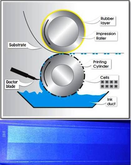
C 2019, 5, 12                                                                                     2 of 7

such as floor coverings, newspapers, and flexible packaging, up to printed electronics [14,27]. A basic
advantage of gravure printing is the excellent image quality and fine resolution that it offers, even
for demanding printing jobs. Printing substrates used in gravure include polymers, glass, metal foils,
and almost all types of papers. The gravure process requires low viscosity (0.05–0.20 Pa.s) and rapidly
dried inks, formulated from soluble materials or nanoparticle dispersions [28]. Thus, the nanometer
size of CDs is ideal for the development of gravure fluorescent inks, since the risk of cylinder cells
clogging during printing is avoided. An additional advantage of CDs comes from the fact that it is
feasible to be produced in large scale using simple synthetic methods and cheap precursors, favoring
their use for low-cost and high-volume industrial applications where gravure is useful.
     A brief description of the principle of the gravure method follows below. The printing unit
includes an engraved cylinder, the ink fountain, a doctor blade, and an impression roller. The engraved
cylinder is made up of recessed (engraved) cells that compose the desired printing image and fill with
ink as the cylinder is immersed and rotated in the ink fountain. The excess ink is removed from the
surfaces that do not have cells using the doctor blade. At the same time, when the substrate passes
through the two cylinders (gravure and impression roller), due to the applied pressure, the ink is
transferred to the substrate, forming the selected image.

2. Materials and Methods

2.1. Materials
    Citric acid and triethylene tetramine (TETA) were purchased from Sigma-Aldrich Chemie GmbH,
Germany. Water-based varnish NAB 056 L 0000 and corona-treated polyethylene terephthalate (PET)
and polyethylene (PE) substrates were supplied from Druckfarben Hellas S.A, Aspropirgos, Attika,
Greece. Optical brightening agent (OBA)-free coated paper was supplied from IGT Testing Systems,
The Netherlands.

2.2. Preparation of Gravure Ink
     CDs were prepared by heating, in a teflon autoclave, a solution of 300 mg of citric acid and
200 mg of TETA in 7 mL of water at 150 ◦ C for four hours. The reaction mixture was then purified
by solid phase extraction using an alumina column, according to [9], and furthermore using dialysis
membrane (3.5 kDa) for 24 h. One mL of the solution of CDs was mixed with 9 mL of the commercial
water-based varnish NAB 056 L 0000 by stirring overnight. The commercial varnish contains a mixture
of styrene-acrylic-emulsion, acrylic resins, and emulsion of polyethylene wax (solid content 58%).
The percentage of the solids in the final suspension was about 1.4% w/w in the CDs.

2.3. Gravure Printing
     The fluorescent ink was printed onto an OBA-free coated paper (150 g/m2 ) obtained from IGT
Testing Systems (404.012.030, CT 2846, black band, ISO 2846) that is used throughout the graphic
industry as a standard paper and on various commercial craft papers. Additionally, corona-treated
PET (12 µm, 56 dynes cm−1 ) and PE (30 µm, 50 dynes cm−1 ) substrates, available from Druckfarben
Hellas S. A., were used.

2.4. Instrumentation
     Optical absorption (OA) spectra in the UV-Vis spectral region were recorded on a Shimadzu
1650 spectrophotometer in the range 200–800 nm, at a sampling step of 0.5 nm with 1.5 nm slits,
using a combination of halogen and deuterium lamps as sources. Photoluminescence (PL) spectra
were obtained from solutions in quartz cuvettes, mounted in a Hitachi F-2500 FL spectrophotometer,
employing a xenon 150 W lamp and a R928 photomultiplier. The excitation and detection slits were
set at 2.5 nm and the accelerating voltage was set to 700 V. Microscopic analysis of the samples was
performed using transmission electron microscopy (TEM) (JEOL-JEM 2100).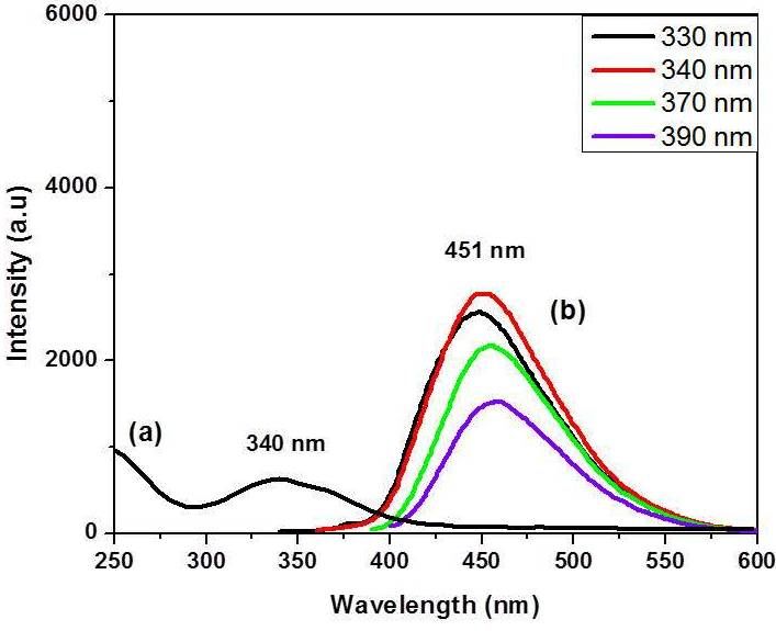
C 2019, 5, 12 3 of 7
C 2019, 5, x FOR PEER REVIEW 3 of 7
Printing teststests
Printing werewere
donedone
using the IGT
using G1-5G1-5
the IGT printability tester
printability withwith
tester a raster patterned
a raster patternedprinting
printing
cylinder named
cylinder by IGT
named as 402.153
by IGT (70 lines/cm,
as 402.153 screen
(70 lines/cm, angleangle
screen 53, stylus angleangle
53, stylus 140, and
140, cell
anddepth 33; 31;
cell depth 33; 31;
30; 29;
30;26;
29;24;
26;20;
24;17;
20; 14;
17; 11
14;μm). The The
11 µm). printing forceforce
printing between the engraved
between the engraveddiscdisc
and and
the substrate was was
the substrate
selected between
selected 100–1000
between N and
100–1000 N the
andprinting speedspeed
the printing was tested in thein
was tested region 0.2–1.0
the region m/s. m/s.
0.2–1.0
Printing teststests
Printing werewere
donedone
also also
using the IGT
using F1 printability
the IGT tester
F1 printability withwith
tester a ceramic, laser-engraved
a ceramic, laser-engraved
cylinder, withwith
cylinder, 4 different engravings.
4 different The The
engravings. printing forceforce
printing between the engraved
between the engraveddisc disc
and and
the substrate
the substrate
was was
selected between
selected 10 and
between 10500
andN,500
andN,theand
printing speed was
the printing tested
speed wasin tested
the region 0.2–1.5
in the regionm/s. Beforem/s.
0.2–1.5
printing, the ink was applied with a pipette in front of a doctor blade and then transferred
Before printing, the ink was applied with a pipette in front of a doctor blade and then transferred to the to
substrate.
the substrate.
2.5. Adhesion
2.5. Adhesion of Inkofon
InkPolymeric
on Polymeric Substrates
Substrates
The The adhesion
adhesion of ofink
ink on
on the
thepolymeric
polymeric printed samples
printed was evaluated
samples according
was evaluated to the ASTMD3359
according to the
standard standard
ASTMD3359 method [ASTM-D3359-09e2, StandardStandard
method [ASTM-D3359-09e2, Test Methods for Measuring
Test Methods AdhesionAdhesion
for Measuring by Tape Test,
ASTM
by Tape International,
Test, USA, 2009].
ASTM International, USA, 2009].
The The printed
printed samples
samples were
were dried
dried at 75 °C◦for
at 75 C for
1515 min.Then,
min. Then,a ascotch
scotchtape
tape(3M,
(3M,width
width of
of 1.5 cm)
cm) was
was applied,
applied,pressed
pressedand andremoved.
removed.The evaluation
The evaluationof of
adhesion is indicated
adhesion by the
is indicated by percentage of residual
the percentage of
area area
residual of inkofon
inkfilm.
on film.
3. Results
3. Results and and Discussion
Discussion
CDsCDswerewere prepared
prepared by by the the hydrothermal
hydrothermal heating
heating of aof mixture
a mixture of citric
of citric acidacid
and and
triethylenetetramine
triethylenetetramine (CDCA-TETA
(CDCA-TETA ) in water
) in water and purified
and purified by solid
by solid phasephase extraction
extraction usingusing an alumina
an alumina
column [9]. The product was further purified by dialysis membrane for
column [9]. The product was further purified by dialysis membrane for the removal of small the removal of small
molecular by-products. The as-prepared CDs exhibited intense blue fluorescence under
molecular by-products. The as-prepared CDs exhibited intense blue fluorescence under UV-radiation UV-radiation
(see (see Figure
Figure 1). TETA
1). TETA and and
citratecitrate
havehavebeenbeen
usedused previously
previously for preparation
for the the preparation of CDs
of CDs using
using
microwaves
microwaves [30,31].[29,30].
Figure 1. Synthetic
Figure procedure
1. Synthetic of CD
procedure ofCA-TETA . Photos
CDCA-TETA with dispersion
. Photos of purified
with dispersion CDs CDs
of purified in water under
in water under
sunlight and UV lamp.
sunlight and UV lamp.
The The
as-prepared CDsCDs
as-prepared had had
a mean diameter
a mean diameterof 2–2.5 nm with
of 2–2.5 a very
nm with narrow
a very narrowsize size
distribution, as as
distribution,
revealed by the
revealed characteristic
by the transmission
characteristic transmissionelectron microscopy
electron microscopy (TEM)
(TEM)image
imagein in
Figure
Figure2. 2.
In In
Figure
Figure 3,
3, the
theUV-Vis
UV-Visabsorption
absorptionand andphotoluminescence
photoluminescencespectra spectraalso
alsoappeared.
appeared.The TheCDCDCA-TETA had had
CA-TETA an an
absorption maximum
absorption maximum at 340atnm
340and
nmaandluminescence maximum
a luminescence at 451 nm
maximum after
at 451 nmirradiation at λmax (340
after irradiation at λmax
nm).(340
The nm).
emission
Theband was slightly
emission band was shifted, from
slightly 448 to 458
shifted, fromnm,
448astoexcitation
458 nm, tuned from 330tuned
as excitation to 390from
nm, 330
respectively.
to 390 nm,Asrespectively.
a consequence, Asana intense blue light
consequence, an was emitted
intense blueunder UV light
light was (Figure
emitted under1, inset).
UV light
(Figure 1, inset).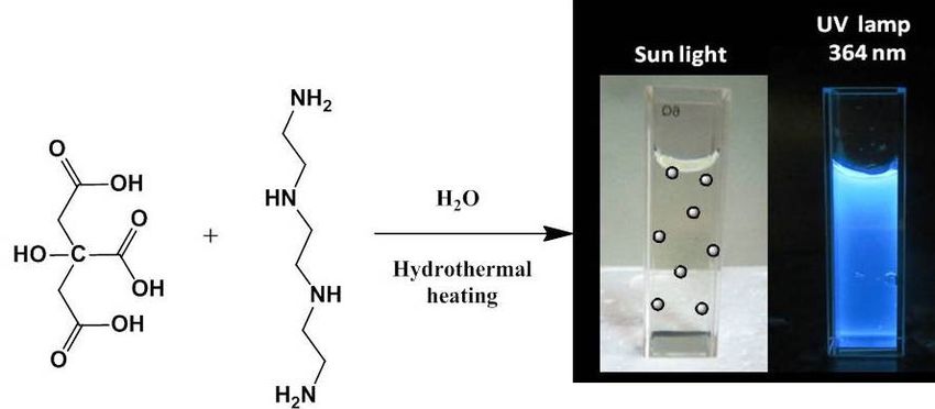
C 2019,
C       5, x12FOR PEER REVIEW
  2019, 5,                                                                                                           4 4of
                                                                                                                         of 77
C 2019, 5, x FOR PEER REVIEW                                                                                         4 of 7

                                          Figure 2. TEM image of CDCA-TETA.
                                          Figure2.2.TEM
                                          Figure    TEMimage
                                                        imageof
                                                              ofCD CA-TETA. .
                                                                 CDCA-TETA

                      Figure 3. UV-Vis (a) and PL (b) spectra of CDCA-TETA dispersed in water.
                      Figure 3. UV-Vis (a) and PL (b) spectra of CDCA-TETA dispersed in water.
                      Figure 3. UV-Vis (a) and PL (b) spectra of CDCA-TETA dispersed in water.
      The water solution of CDCA-TETA was then mixed with a common industrial acrylic resin suitable
     The water solution of CDCA-TETA was then mixed with a common industrial acrylic resin suitable
for gravure   printing
      The water          in several
                  solution             ratios.
                             of CDCA-TETA    wasThe   as-prepared
                                                   then   mixed withinks   showed industrial
                                                                        a common     stable photoluminescence           (PL)
                                                                                                   acrylic resin suitable
for gravure printing in several ratios. The as-prepared inks showed stable photoluminescence (PL)
properties
for gravureunder     theinproper
              printing      severalconditions.        Because of their
                                       ratios. The as-prepared             nanometer
                                                                    inks showed          sizephotoluminescence
                                                                                     stable     (2–2.5 nm), CDs were    (PL)
properties under the proper conditions. Because of their nanometer size (2–2.5 nm), CDs were
formulated    very  easily  into  the   low-viscosity     gravure  ink,  giving   an
properties under the proper conditions. Because of their nanometer size (2–2.5 nm),  ideal   dispersion    in the
                                                                                                                CDs solvent
                                                                                                                       were
formulated very easily into the low-viscosity gravure ink, giving an ideal dispersion in the solvent
system and very
formulated    avoiding
                    easilythe  settlement
                            into             in the inkgravure
                                  the low-viscosity       bottle for  long
                                                                   ink,     periods
                                                                         giving       of time
                                                                                 an ideal       (months).
                                                                                             dispersion    inCD-ink      was
                                                                                                               the solvent
system and avoiding the settlement in the ink bottle for long periods of time (months). CD-ink was
finally  printed  on various    coated    paper   and   polymeric   substrates    (polyethylene
system and avoiding the settlement in the ink bottle for long periods of time (months). CD-ink was   terephthalate,     PET,
finally printed on various coated paper and polymeric substrates (polyethylene terephthalate, PET,
polyethylene,
finally  printedPE)
                  on using
                     various gravure
                                coatedprintability
                                          paper and testers.    Thesubstrates
                                                        polymeric    high-quality   printed matters
                                                                                 (polyethylene           showed intense
                                                                                                    terephthalate,     PET,
polyethylene, PE) using gravure printability testers. The high-quality printed matters showed intense
photoluminescence      that  remained,     without    obvious   reduction,   after at  least two   weeks
polyethylene, PE) using gravure printability testers. The high-quality printed matters showed intense       (see  Figure  4).
photoluminescence that remained, without obvious reduction, after at least two weeks (see Figure 4).
The  stability of the printed    structures    on  paper,   PET, and    PE substrates    were   tested
photoluminescence that remained, without obvious reduction, after at least two weeks (see Figure 4).    according     to the
The stability of the printed structures on paper, PET, and PE substrates were tested according to the
standard
The        ISOof
     stability 2836/2004
                  the printed[31].  In brief, aon
                                 structures     part  of thePET,
                                                  paper,     printed
                                                                 and surface   was placed
                                                                        PE substrates    werebetween     two filter to
                                                                                               tested according       paper
                                                                                                                         the
standard ISO 2836/2004 [31]. In brief, a part of the printed surface was placed between two filter paper
sheets   soaked  into different    liquids,  such    as water,  diluted   alkali (1%   NaOH      in water),
standard ISO 2836/2004 [31]. In brief, a part of the printed surface was placed between two filter paper      and   alcohol
sheets soaked into different liquids, such as water, diluted alkali (1% NaOH in water), and alcohol
(96% ethanol),
sheets           and different
        soaked into   kept under      pressure
                                   liquids,  suchforas24  h or 10
                                                        water,     min (the
                                                                diluted      alkali
                                                                          alkali (1%exposure).
                                                                                       NaOH in All      testsand
                                                                                                    water),    showed     no
                                                                                                                    alcohol
(96% ethanol), and kept under pressure for 24 h or 10 min (the alkali exposure). All tests showed no
obvious
(96%       decrease
       ethanol), andofkept
                        the under
                             luminescence
                                      pressureoffor the24printed
                                                          h or 10 samples.   Furthermore,
                                                                   min (the alkali   exposure).as shown
                                                                                                    All testsinshowed
                                                                                                                [Figure no5],
obvious decrease of the luminescence of the printed samples. Furthermore, as shown in [Figure 5],
luminescence    intensity  of the   printed  matters    was  directly  proportional   to the  thickness
obvious decrease of the luminescence of the printed samples. Furthermore, as shown in [Figure 5],         of  the ink  layer.
luminescence intensity of the printed matters was directly proportional to the thickness of the ink
luminescence intensity of the printed matters was directly proportional to the thickness of the ink
layer.
layer.
C 2019,
C 5, x12FOR PEER REVIEW
2019, 5, 5 5of
of 77
Figure
Figure 4.4.Photos
Photosof
ofpaper
paper(a,b)
(a,b)and
andpolymeric
polymeric(c,d)
(c,d)substrates,
substrates,printed
printedwith
withfluorescent
fluorescent CDs
CDs ink,
ink,under
under
visible
visible (a,c)
(a,c) and
and UV (365 nm) (b,d) light.
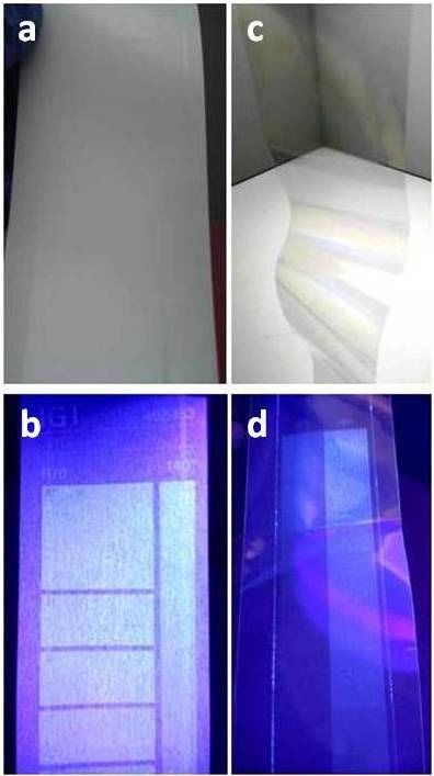
Figure
Figure 5.
5. (Upper)
(Upper) Schematic
Schematic representation
representation of
of gravure
gravure printing
printing technique.
technique. (Lower)
(Lower) Paper
Paper substrate
substrate
printed
printed with fluorescent CDs ink, under UV (365nm) light, showing gradient luminescence in
with fluorescent CDs ink, under UV (365nm) light, showing gradient luminescence in
accordance
accordance toto layer
layer thickness.
thickness.
In
In addition,
addition, CD-ink
CD-ink showed
showed excellent
excellent ink
ink adhesion
adhesion to
to substrates
substrates (99%
(99% according
according toto ASTM
ASTM D3359
D3359
test method),a acritical
test method), critical parameter
parameter in packaging
in packaging applications.
applications. It should
It should be notedbethat
noted
polymerthat substrates
polymer
substrates generally
generally have have low-energy
low-energy surfaces,
surfaces, causing causingproblems,
adhesion adhesion problems,
due to the due to the
higher higher
surface surface
tension of
tension of water-based
water-based inks. This
inks. This means that means that in the as-prepared
in the as-prepared CD-ink, basic CD-ink, basic such
parameters, parameters, such as
as ink viscosity,
ink viscosity,
substrate substrate
surface energy,surface energy,
ink surface ink surface
tension, tension,
interaction interactiontreated
of ink-corona of ink-corona treated
substrate, substrate,
printing speed,
printing speed,were
and pressure, and perfectly
pressure,combined.
were perfectly combined.
4. ConclusionsC 2019, 5, 12 6 of 7
4. Conclusions
In conclusion, in this work we showed that blue-emitting CDs were used successfully for the
preparation of fluorescent inks suitable in gravure printing. CD-ink was printed on paper and
polymer film showing intense and stable, luminescence, proportional to the thickness of the ink layer.
The printed structures also showed stability in various liquids tested, according to the related ISO,
and excellent ink adhesion to substrates.
Author Contributions: A.K. prepared the products and performed the characterization. V.B. performed the
gravure printing and was responsible for the preparation of the ink. V.G. supervised the work and wrote the
manuscript. All co-authors provided advice and helped write the manuscript.
Acknowledgments: The authors gratefully acknowledge (a) Mary Kollia and the Laboratory of Electron
Microscopy and Microanalysis, School of Natural Sciences, University of Patras for the TEM measurements; (b)
IOANNOU ICR S.A. manufacturer of rotogravure cylinders for the donation of the IGT G1-5 printability tester
used in this research; (c) D. Mantis from Druckfarben Hellas S.A. for the donation of the resin system and corona
treated substrates; and (d) G. Vlahopoulos for his helpful comments and technical support.
Conflicts of Interest: The authors declare no conflicts of interest.
References
1. Ying, L.S.; Shen, W.; Gao, Z. Carbon quantum dots and their applications. Chem. Soc. Rev. 2015, 44, 362–381.
[CrossRef]
2. Georgakilas, V.; Perman, J.A.; Tucek, J.; Zboril, R. Broad family of carbon nanoallotropes: Classification,
chemistry, and applications of fullerenes, carbon dots, nanotubes, graphene, nanodiamonds, and combined
superstructures. Chem. Rev. 2015, 115, 4744–4822. [CrossRef]
3. Zhao, A.; Chen, Z.; Zhao, C.; Gao, N.; Ren, J.; Qu, X. Recent advances in bioapplications of C-dots. Carbon
2015, 85, 309–327. [CrossRef]
4. Mishra, V.; Patil, A.; Thakur, S.; Kesharwani, P. Carbon dots: Emerging theranostic nanoarchitectures.
Drug Discov. Today 2018, 23, 1219–1232. [CrossRef] [PubMed]
5. Wu, Z.L.; Liu, Z.X.; Yuan, Y.H. Carbon dots: Materials, synthesis, properties and approaches to
long-wavelength and multicolor emission. J. Mater. Chem. B 2017, 5, 3794–3809. [CrossRef]
6. Han, M.; Zhu, S.; Lu, S.; Song, Y.; Feng, T.; Tao, S.; Liu, J.; Yang, B. Recent progress on the photocatalysis of
carbon dots: Classification, mechanism and applications. Nano Today 2018, 19, 201–218. [CrossRef]
7. Atabaev, T. Doped carbon dots for sensing and bioimaging applications: A minireview. Nanomaterials 2018,
8, 342. [CrossRef] [PubMed]
8. Bourlinos, A.B.; Stassinopoulos, A.; Anglos, D.; Zboril, R.; Georgakilas, V.; Giannelis, E.P. Photoluminescent
carbogenic dots. Chem. Mater. 2008, 20, 4539–4541. [CrossRef]
9. Koutsioukis, A.; Akouros, A.; Zboril, R.; Georgakilas, V. Solid phase extraction for the purification of violet,
blue, green and yellow emitted Carbon dots. Nanoscale 2018, 10, 11293–11296. [CrossRef]
10. Gong, X.; Hu, Q.; Paau, M.C.; Zhang, Y.; Shuang, S.; Dong, C.; Choi, M.M. Red-green-blue fluorescent
hollow carbon nanoparticles isolated from chromatographic fractions for cellular imaging. Nanoscale 2014, 6,
8162–8170. [CrossRef]
11. Liu, Y.; Zhou, L.; Li, Y.; Deng, R.; Zhang, H. Highly fluorescent nitrogen-doped carbon dots with excellent
thermal and photo stability applied as invisible ink for loading important information and anti-counterfeiting.
Nanoscale 2017, 9, 491–496. [CrossRef]
12. Sk, M.P.; Chattopadhyay, A. Induction coil heater prepared highly fluorescent carbon dots as invisible ink
and explosive sensor. RSC Adv. 2014, 4, 31994–31999. [CrossRef]
13. Hu, G.; Kang, J.; Ng, L.W.; Zhu, X.; Howe, R.C.; Jones, C.G.; Hersham, M.C.; Hasan, T. Functional inks and
printing of two-dimensional materials. Chem. Soc. Rev. 2018, 47, 3265–3300. [CrossRef]
14. Yang, W.; Wang, C. Graphene and the related conductive inks for flexible electronics. J. Mater. Chem. C 2016,
4, 7193–7207. [CrossRef]
15. Lee, H.; Lee, J.; Seong, B.; Jang, H.S.; Byun, D. Printing Conductive Micro-Web Structures via Capillary
Transport of Elastomeric Ink for Highly Stretchable Strain Sensors. Adv. Mater. Technol. 2018, 3, 1700228.
[CrossRef]C 2019, 5, 12 7 of 7
16. Bonaccorso, F.; Bartolotta, A.; Coleman, J.N.; Backes, C. 2D-Crystal-Based Functional Inks. Adv. Mater. 2016,
28, 6136–6166. [CrossRef]
17. Koutsioukis, A.; Georgakilas, V.; Belessi, V.; Zboril, R. Highly Conductive Water-Based Polymer/Graphene
Nanocomposites for Printed Electronics. Chemistry 2017, 23, 8268–8274. [CrossRef]
18. Karagiannidis, P.G.; Hodge, S.A.; Lombardi, L.; Tomarchio, F.; Decorde, N.; Milana, S.; Leary, R.K.;
Midgley, P.A.; Pugno, N.M.; Torrisi, F.; et al. Microfluidization of graphite and formulation of graphene-based
conductive inks. ACS Nano 2017, 11, 2742–2755. [CrossRef]
19. Xiao, L.; Sun, H. Novel properties and applications of carbon nanodots. Nanoscale Horizons 2018, 3, 565–597.
[CrossRef]
20. Kalytchuk, S.; Wang, Y.; Poláková, K.; Zboril, R. Carbon Dot Fluorescence-Lifetime-Encoded
Anti-Counterfeiting. ACS Appl. Mater. Interfaces 2018, 10, 29902–29908. [CrossRef]
21. Zhu, S.; Meng, Q.; Wang, L.; Zhang, J.; Song, Y.; Jin, H.; Zhang, K.; Yang, B.; Sun, H.; Wang, H.; et al. Highly
photoluminescent carbon dots for multicolor patterning, sensors, and bioimaging. Angew. Chem. 2013, 125,
4045–4049. [CrossRef]
22. Zhang, J.; Yu, S.H. Carbon dots: Large-scale synthesis, sensing and bioimaging. Mater. Today 2016, 19,
382–393. [CrossRef]
23. Wang, F.; Xie, Z.; Zhang, B.; Liu, Y.; Yang, W.; Liu, C.Y. Down-and up-conversion luminescent carbon dot
fluid: Inkjet printing and gel glass fabrication. Nanoscale 2014, 6, 3818–3823. [CrossRef]
24. Wang, C.F.; Cheng, R.; Ji, W.Q.; Ma, K.; Ling, L.; Chen, S. Recognition of Latent Fingerprints and Ink-Free
Printing Derived from Interfacial Segregation of Carbon Dots. ACS Appl. Mater. Interfaces 2018, 10,
39205–39213. [CrossRef]
25. Li, M.; Yao, W.; Liu, J.; Tian, Q.; Liu, L.; Ding, J.; Xue, Q.; Lu, Q.; Wu, W. Facile synthesis and screen printing
of dual-mode luminescent NaYF 4: Er, Yb (Tm)/carbon dots for anti-counterfeiting applications. J. Mater.
Chem. C 2017, 5, 6512–6520. [CrossRef]
26. Liu, S.S.; Wang, C.F.; Li, C.X.; Wang, J.; Mao, L.H.; Chen, S. Hair-derived carbon dots toward versatile
multidimensional fluorescent materials. J. Mater. Chem. C 2014, 2, 6477–6483. [CrossRef]
27. Kipphan, H. (Ed.) Handbook of Print Media—Technologies and Production Methods, 1st ed.; Springer: Berlin,
Germany, 2001; pp. 48–52.
28. Kahn, B.E. Patterning Processes for Flexible Electronics. Proc. IEEE 2015, 103, 497–517. [CrossRef]
29. Vassilakopoulou, A.; Georgakilas, V.; Koutselas, I. Encapsulation and protection of carbon dots within
MCM-41 material. J. Sol-Gel Sci. Technol. 2017, 82, 795–800. [CrossRef]
30. Vassilakopoulou, A.; Georgakilas, V.; Vainos, N.; Koutselas, I. Successful entrapment of carbon dots within
flexible free-standing transparent mesoporous organic-inorganic silica hybrid films for photonic applications.
J. Phys. Chem. Solids 2017, 103, 190–196. [CrossRef]
31. Bates, I.; Mihić, J.; Radić Seleš, V.; Vuksanović, A. Analysis of Samples Treated by Resistance Test Method
Exposed to Accelerated Aging. Acta Graph. 2015, 26, 23–30.
© 2019 by the authors. Licensee MDPI, Basel, Switzerland. This article is an open access
article distributed under the terms and conditions of the Creative Commons Attribution
(CC BY) license (http://creativecommons.org/licenses/by/4.0/).You can also read