Quasi-Continuous Metasurfaces for Orbital Angular Momentum Generation - arXiv
←
→
Page content transcription
If your browser does not render page correctly, please read the page content below
IEEE ANTENNAS AND WIRELESS PROPAGATION LETTERS, VOL. XX, 2019                                                                                 1

                                                   Quasi-Continuous Metasurfaces for Orbital Angular
                                                                Momentum Generation
                                                       Menglin L. N. Chen, Member, IEEE, Li Jun Jiang, Fellow, IEEE, and Wei E. I. Sha, Senior Member, IEEE
arXiv:1903.01097v1 [physics.class-ph] 4 Mar 2019

                                                      Abstract—A quasi-continuous composite perfect electric                     using geometric-phase based metasurface is to make the local
                                                   conductor-perfect magnetic conductor metasurface and a sys-                   phase change equal to eilφ . Various prototypes of scatterers on
                                                   tematic metasurface design process are proposed for the orbital               these metasurfaces have been proposed for OAM generation,
                                                   angular momentum (OAM) generation. The metasurfaces reflect
                                                   the incident left circularly polarized (LCP)/right circularly polar-          such as split-ring resonators [23, 24], L-shaped and elliptical
                                                   ized (RCP) plane wave to RCP/LCP vortex beams carrying OAM                    nano antennas [25, 26]. However, the performance could be
                                                   at normal or oblique direction. Unlike conventional metasurfaces              degraded due to the unwanted coupling among scatterers and
                                                   that are composed of discrete scatterers, the scatterers on the               high-order diffraction. Hence, a lot of efforts need to be taken
                                                   proposed metasurface form a quasi-continuous pattern. The                     in the design and optimization of scatterers.
                                                   patterning of the metasurface is calculated through grating
                                                   vectors, and no optimization of single scatterer is required.                    In this work, we present a quasi-continuous metasurface
                                                   Furthermore, the distortions from local-response discontinuity                for OAM generation. The metasurface contains an anisotropic
                                                   of discrete scatterers are avoided. This letter provides great                perfect electric conductor (PEC) layer and an isotropic perfect
                                                   convenience to high-quality OAM generation.                                   magnetic conductor (PMC) layer. It reflects the incident left
                                                     Index Terms—Grating vector, orbital angular momentum                        circularly polarized (LCP)/right circularly polarized (RCP)
                                                   (OAM), quasi-continuous metasurface.                                          plane wave to a RCP/LCP wave, along with a locally mod-
                                                                                                                                 ulated geometric phase. The phase distribution on the whole
                                                                            I. I NTRODUCTION                                     metasurface satisfies ei(lφ+kx x+ky y) so that an OAM of order l
                                                                                                                                 can be generated at the k-space position (kx , ky ), where kx and

                                                   I   T is known since 1992 that Laguerre-Gaussian modes carry
                                                       well-defined orbital angular momentum (OAM). Those
                                                   modes have an azimuthally dependent phase factor, eilφ , where
                                                                                                                                 ky are the transverse wavenumbers. The PEC layer presents
                                                                                                                                 a quasi-continuous pattern and the PMC layer can be realized
                                                                                                                                 using any artificial high impedance surface.
                                                   φ is the azimuthal angle, and l is the OAM index [1].
                                                   Since then, OAM has been applied in communications [2],
                                                   imaging [3, 4], and so on. For example, OAM-based multi-                                           II. M ETHODOLOGY
                                                   plexing and demultiplexing have been implemented at different                    Figure 1(a) illustrates one type of composite PEC-PMC
                                                   frequency regimes [5, 6]. As a simple and newly discovered                    metasurfaces to produce vortex wave with l = ±2 [27].
                                                   multiplexing approach, OAM multiplexing needs to be studied                   The top PEC layer is composed of concentric metal loops.
                                                   to overcome the issues of power decay, sensitivity to mis-                    A mushroom-like high impedance surface acting as the PMC
                                                   alignment, and mode crosstalk for practical applications [7–9].               layer is put beneath the PEC layer. Any local area on the
                                                   Furthermore, OAM is promising for applications related to the                 metasurface can be considered as a PEC scatterer on top of
                                                   light-matter interaction, such as the manipulation of particles               a PMC scatterer. One unit cell is extracted and shown in
                                                   and detection of spinning objects [10, 11].                                   Fig. 1(b). The geometric and material parameters are the same
                                                      To introduce OAM to a plane wave, the azimuthal phase                      as in our previous work [27]. The size of one mushroom struc-
                                                   factor, eilφ needs to be added along the wave path. Devices for               ture is around λ0 /7. Therefore, the periodically distributed
                                                   OAM generation include spiral phase plate [12], q plates [13],                mushroom can be considered as an isotropic, homogeneous
                                                   gratings [14], metasurfaces [15–17] and photonic crystals [18].               plane. Complex Jones matrix (Jxx Jxy ; Jyx Jyy ) is used to
                                                   With high flexibility, metasurfaces have been widely used                     model the scatterer. Since it is symmetric about the x and
                                                   in wave manipulation [19–21]. Particularly, as one type of                    y axes, we have Jxy = Jyx = 0. The metal-strip array
                                                   metasurfaces, geometric-phase based metasurface changes the                   behaves like a parallel-plate waveguide. The cut-off frequency
                                                   local phase of electromagnetic (EM) waves by scatterers with                                                           √
                                                                                                                                 of corresponding TE1 mode is 1/(2g µǫ), where g is the
                                                   varying orientations. This phase modification originates from                 gap between adjacent metal strips [28]. Below the cut-off
                                                   the change in the polarization state along different paths on the             frequency, the y-polarized component will be totally reflected
                                                   Poincaré sphere [22]. The key point to produce OAM waves by                  with a π phase shift (Jyy = −1). The penetrated x-polarized
                                                                                                                                 component will be reflected by the PMC plane without phase
                                                     M. L. N. Chen and L. J. Jiang are with the Department of Electrical and
                                                   Electronic Engineering, The University of Hong Kong, Hong Kong (e-mail:       shift (Jxx = 1). When the composite structure is illuminated
                                                   menglin@connect.hku.hk; jianglj@hku.hk).                                      by a circularly polarized wave, the polarization state will be
                                                     W. E. I. Sha is with the Key Laboratory of Micro-nano Electronic Devices    changed from left to right and vice versa. It should be noticed
                                                   and Smart Systems of Zhejiang Province, College of Information Science and
                                                   Electronic Engineering, Zhejiang University, Hangzhou 310027, China (email:   that the whole metasurface is composed of those scatterers
                                                   weisha@zju.edu.cn).                                                           with different orientations. Therefore, besides the polarization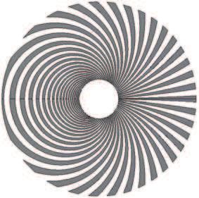
IEEE ANTENNAS AND WIRELESS PROPAGATION LETTERS, VOL. XX, 2019 2
y y
g/2 g/2 Kg
α
ϕ r
θ
d2 t ϕ
x
x
d1 a
p p 2r
(a) (b) Fig. 2. Arbitrary metal-strip pattern modeled by the grating vector Kg which
is normal to the tangent of the metal strips.
Fig. 1. Schematic pattern of the PEC-PMC metasurface. (a) Top view of the
whole metasurface. The inclination angle of the metal strips is denoted by α. 0.6 0.6
(b) A scatterer in the metasurface. 0.4 0.5
Kg 0.2
Kg 0.4
0 0.3
flip, the reflected wave is accompanied by an additional phase -0.2 0.2
which is equal to e±2iα , where α is the inclination angle -0.4 0.1
between the metal-strip tangent and x axis. The plus/minus -0.6
sign is taken when the incident wave is LCP/RCP. As can (a) (b)
be read from the figure, α = φ + π/2. Thus, the reflected
wave carries an OAM of order ±2. Usually, for geometric- Fig. 3. The calculated g when (a) m = 0.5, a = b = 0, D = 0, A = 1 and
(b) m = 0.5, a = b = 0, D = π/2, A = 1.
phase based metasurfaces, rotation of the discrete scatterers
breaks the periodicity along the x and y directions, resulting
in the undesired mutual coupling between the nearest-neighbor To produce vortex beams radiating at the desired direction, θ
scatterers. However, in the composite PEC-PMC metasurface, should satisfy
individual control of the two orthogonal polarizations is real-
ized by the PEC and PMC layers, respectively. No rotation θ(r, φ) = mφ + ar cos φ + br sin φ + D, (2)
operation is required for the scatterers on the PMC layer. where m = l/2 and is also called the topological charge of the
Meanwhile, induced current is continuously guided along the structure. The second and third terms in θ(r, φ) are introduced
smoothly connected metal strips on the PEC layer. From this for realizing oblique reflection. a = kx /2, b = ky /2. D is
point of view, compared to the discrete geometric-phase based a phase constant that determines the direction of Kg at the
scatterers, the unwanted mutual coupling among the PEC- origin.
PMC scatterers is significantly reduced. Moreover, by keeping To ensure the continuity of the grating, it is required that
the local period small enough, no high-order diffraction exists. ∇ × Kg = 0 [29]. By substituting (2) into (1), the general
Regarding vortex beams carrying arbitrary orders of OAM, solution of K0 fulfilling the zero divergence condition is of
in conventional metasurfaces, discrete scatterers are placed the form
at specific locations with pre-designed orientations [23–26]. ear sin φ−br cos φ
K0 = A , (3)
However, the discontinuity and aperiodicity induced by the rm
discrete scatterers will distort the near-field pattern [27] and where A is a scaling factor.
lower the efficiency. To achieve a continuous phase shift on It is supposed that the closed metal strip could be mathe-
the metasurface, the discrete scatterers should be continuously matically described by a curve equation g(r, φ) = C. ∇g is
and smoothly connected. For practical implementation, we the normal vector of the curve. Therefore, ∇g = Kg and it is
consider the metal strips as a grating and model them using solved by integrating Kg over an arbitrary path:
grating vectors. An arbitrary metal-strip pattern is drawn in Z (r,φ0 ) Z (r,φ)
Fig. 2. The grating vector is perpendicular to the tangent of
g(r, φ) = Kr dr + rKφ dφ. (4)
metal strips. In other words, the grating vector is the normal (r0 ,φ0 ) (r,φ0 )
vector of the curve of the metal strips. In polar coordinates, it
In Fig. 3, we show the calculated g when θ(r, φ) = mφ+D.
is written as
As expected, the orientation of the contour line coincides with
θ(r, φ). The grating vector is perpendicular to the contour line
Kg (r, φ) = Kr r̂ + Kφ φ̂ and its initial orientation at φ = 0 is determined by D which
= K0 (r, φ) cos[θ(r, φ) − φ]r̂ (1) is horizontal when D = 0 and vertical when D = π/2.
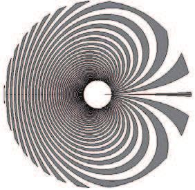
A Lee-type binary grating is then generated from g [30].
+ K0 (r, φ) sin[θ(r, φ) − φ]φ̂,
Figure 4 shows two gratings with different scaling factors A.
where K0 (r, φ) is the local spatial frequency at (r, φ). The grating is a desired pattern for the PEC layer. The local
As discussed, the orientation of the local metal segments orientations of the two patterns are identical while the local
characterized by θ determines the geometric phase, which periods are different. Since adjacent metal strips function as a
will contribute to the phase shift for the wave manipulation. parallel-plate waveguide, proper value of A needs to be chosen
IEEE ANTENNAS AND WIRELESS PROPAGATION LETTERS, VOL. XX, 2019                                                                                             3

                                                                                                  y                                   y

                                                                                                               x                                   x
                                                                                      z                       12.7 dBi     z                       π
                    (a)                                 (b)

Fig. 4. The binary grating generated from the calculated g in Fig. 3(b) when                   (a)                                  (b)
the scaling factor (a) A = 100 and (b) A = 300.                                                   y                                   y

                                                                                                              -34.5                                -π

                                                                                                               x                                   x
                                                                                      z                                    z
                           0        1             -π          π

                          (a)                    (b)
                                                                                               (c)                                  (d)

                                                                                Fig. 6. Simulated far-field radiation patterns for the metasurface with m =
                                                                                0.5. (a) Directivity and (b) phase of the cross-polarized (RCP) component;
                                                                                (c) directivity and (d) phase of the co-polarized (LCP) component.

                           0       1               -π         π
                                                                                components are ix = 1, iy = ±i. The reflected wave
                          (c)                    (d)                            components rx = Jxx = 1, ry = ±iJyy = ±ieip . The am-
                                                                                plitude of the converted
                                                                                                      √ cross-circularly√polarized component
Fig. 5. Simulated field distributions at a transverse plane 20 mm away from
the metasurface with m = 0.5. (a) Amplitude and (b) phase of the field when
                                                                                is a = (rx ± iry )/ 2 = (1 − eip )/ 2. The efficiency of
the metal strips are placed on an ideal PMC boundary; (c) amplitude and (d)     the unit cell, which is equal to the ratio of the power of the
phase of the field when the metal strips are placed on the mushroom-like high   converted wave to that of the incident wave, is |1 − eip |2 /4.
impedance surface.
                                                                                Clearly, for the ideal case that p = π, the efficiency is 1. The
                                                                                metasurface shown in Fig. 1 has been demonstrated to exhibit
so that their gap is small enough to guarantee that the operating               nearly perfect efficiency [27]. For the metasurface with non-
frequency is far below the cut-off frequency of the TE1 mode.                   uniformly distributed metal strips, we calculate the efficiency
                                                                                using the power of the reflected RCP wave divided by that
                                                                                of the incident wave. The efficiency of the metasurface for
                               III. S IMULATION                                 Fig. 5 is 94%. The far-field radiation patterns of both the co-
   For the PEC layer in Fig. 4(b), the outer radius of the pattern              polarized component and cross-polarized component are plot-
is 100 mm and the inner radius is 5 mm. Two scenarios                           ted in Fig. 6. The maximum directivity for the RCP component
are compared in which the ideal PMC boundary and the                            is 12.7 dBi and it is only 5.5 dBi for the LCP component.
mushroom-like high impedance surface are applied beneath                        Moreover, the directivity for the converted component presents
the PEC layer, respectively. Simulations are done in CST                        a donut shape with a gradual phase change around the vortex
MWS. The metasurface is illuminated by a LCP Gaussian                           axis while the co-polarized component does not show such
wave with the beam waist of 50 mm at 6.2 GHz. Figure 5                          feature.
shows the amplitude and phase distributions of the reflected                       In following simulations, we will use the ideal PMC bound-
RCP field component at a transverse plane 20 mm away from                       ary for simplicity. Metasurfaces for generating OAM with
the metasurface. We see the field distribution of an OAM wave                   other orders can be built based on the same procedure. The
with l = 1. A clear phase singularity is observed. The phase                    top metal-strip layers with the topological charge m = 1.5 and
encounters a total 2π change along a closed path enclosing                      m = 2 are shown in Fig. 7. The far-field directivity and phase
the center. The simulated fields in the two scenarios show a                    patterns indicate the successful generation of OAM with order
good agreement with each other.                                                 l = 3 and l = 4.
   The efficiency of the unit cell can be used to evaluate the                     Regarding oblique reflection to be manipulated, transverse
performance of the design. The parameters for the mushroom-                     wavenumbers, kx and ky need to be introduced. They are cal-
like high impedance surface keep same for all metasurfaces.                     culated based on the desired reflected wave direction (θ0 , φ0 ):
Hence, we can assume Jxx = 1 all the time. The y-polarized
                                                                                          kx = k0 cos φ0 sin θ0 ,        ky = k0 sin φ0 sin θ0 .        (5)
component will be totally reflected due to presence of the
ground plane. However, the reflection phase depends on the                      Then, the required orientation θ(r, φ) of metal strips is found
gap between the metal strips. Here, we write Jyy = eip .                        from (2). By following the calculations in (3) and (4), the
For the incidence of a circularly polarized wave, incident                      pattern of the PEC layer can be generated. Figure 8 displays
IEEE ANTENNAS AND WIRELESS PROPAGATION LETTERS, VOL. XX, 2019                                                                                                4

                    (a)                               (b)
                       y                                 y
                                                                                              (a)                                        (b)
                                                                                                 y                                          y

                                     x                                 x
           z                                 z

                    (c)                               (d)                                                         x                                          x
                       y                                 y                        z                                          z

                                                                                              (c)                                        (d)
                                                                                                 y                                         y
                                     x                                 x
           z                                 z

                    (e)                               (f)

Fig. 7. The quasi-continuous PEC-PMC metasurfaces to produce OAM at                                               x                                          x
normal direction and their far-field radiation patterns. When m = 1.5, (a) the
top view of the PEC layer; (c) directivity and (e) phase of the RCP component.    z                                          z
When m = 2, (b) the top view of the PEC layer; (d) directivity and (f) phase
of the RCP component.
                                                                                              (e)                                        (f)
the reflected OAM waves at different directions. As expected,
                                                                                 Fig. 8. The quasi-continuous PEC-PMC metasurfaces to produce OAM at
the OAM indexes are 1 in Fig. 8(a) and 3 in Fig. 8(b).                           oblique directions and their far-field radiation patterns. When m = 0.5, θ0 =
The simulated directivity is consistent with our objective.                      20◦ , φ0 = 0, (a) the top view of the PEC layer; (c) directivity and (e) phase
It is worth noting that the proposed design is not limited                       of the RCP component. When m = 1.5, θ0 = 10◦ , φ0 = 90◦ , (b) the top
                                                                                 view of the PEC layer; (d) directivity and (f) phase of the RCP component.
to radio regime, as long as the responses of the PMC and
PEC layers are replicated. For example, in terahertz regime,
graphene-based high-impedance surfaces [31] and dielectric                                                ACKNOWLEDGMENT
metasurfaces [32] can be used as magnetic mirrors. In optical
regime, dielectric metamaterials acting as perfect reflectors                      This work was supported in part by the Research Grants
with the reflection phases of π and zero could be applied [33].                  Council of Hong Kong GRF 17209918, AOARD FA2386-17-
                                                                                 1-0010, NSFC 61271158, HKU Seed Fund 201711159228,
                           IV. C ONCLUSION                                       and Hundred Talents Program of Zhejiang University under
   We have proposed a quasi-continuous PEC-PMC meta-                             Grant No. 188020*194231701/208.
surface with a systematic design route to generate vortex
beams at normal and oblique directions. The introduction
                                                                                                               R EFERENCES
of spatial phase to the incident plane wave is based on the
concept of geometric phase. Specifically, the local phase shift                  [1] L. Allen, M. W. Beijersbergen, R. J. C. Spreeuw, and J. P.
depends on the orientation of the metal strips of the PEC                            Woerdman, “Orbital angular momentum of light and the
layer. Patterning of the metal strips is accomplished with the                       transformation of Laguerre-Gaussian laser modes,” Phys.
assistance of grating vector, which offers a simple and effective                    Rev. A, vol. 45, pp. 8185-8189, 1992.
way to the design of the whole metasurface. Different from                       [2] A. E. Willner et al., “Optical communications using orbital
existing design protocols for geometric-phase based metasur-                         angular momentum beams,” Adv. Opt. Photonics, vol. 7,
faces, complicated optimization process of single scatterer                          pp. 66-106, 2015.
is not needed. Furthermore, thanks to the quasi-continuous                       [3] F. Tamburini, G. Anzolin, G. Umbriaco, A. Bianchini, and
geometries, high-order diffraction from discrete scatterers are                      C. Barbieri, “Overcoming the Rayleigh criterion limit with
avoided.                                                                             optical vortices,” Phys. Rev. Lett., vol. 97, p. 163903, 2006.
IEEE ANTENNAS AND WIRELESS PROPAGATION LETTERS, VOL. XX, 2019 5
[4] K. Liu, Y. Q. Cheng, Z. C. Yang, H. Q. Wang, Y. L. Qin, [21] H. Y. Shi et al.,, “Generation of multiple modes mi-
and X. Li, “Orbital-angular-momentum-based electromag- crowave vortex beams using active metasurface,” IEEE
netic vortex imaging,” IEEE Antennas Wireless Propag. Antennas and Wireless Propag. Lett., vol. 18, no. 1, pp.
Lett., vol. 14, pp. 711-714, 2015. 59-63, 2019.
[5] F. Tamburini, E. Mari, A. Sponselli, B. Thidé, A. Bian- [22] M. V. Berry, “The adiabatic phase and Pancharatnam’s
chini, and F. Romanato, “Encoding many channels on the phase for polarized light,” J. Mod. Opt., vol. 34, no. 11,
same frequency through radio vorticity: first experimental pp. 1401-1407, 1987.
test,” New J. Phys., vol. 14, p. 033001, 2012. [23] M. L. N. Chen, L. J. Jiang, and W. E. I. Sha, “Ultrathin
[6] Y. Yan et al., “High-capacity millimetre-wave communica- complementary metasurface for orbital angular momen-
tions with orbital angular momentum multiplexing,” Nat. tum generation at microwave frequencies,” IEEE Trans.
Commun., vol. 5, p. 4876, 2014. Antennas and Propag., vol. 65, pp. 396-400, 2017.
[7] G. D. Xie et al., “Performance metrics and design [24] M. L. N. Chen, L. J. Jiang, and W. E. I. Sha, “Orbital an-
considerations for a free-space optical orbital-angular- gular momentum generation and detection by geometric-
momentummultiplexed communication link,” Optica, vol. phase based metasurfaces,” Appl. Sci., vol. 8, no. 362,
2, pp. 357-365, 2015. 2018.
[8] N. B. Zhao, X. Y. Li, G. F. Liu, and J. M. Kahn, “Capacity [25] E. Karimi, S. A. Schulz, I. De Leon, H. Qassim, J.
limits of spatially multiplexed free-space communication,” Upham, and R. W. Boyd, “Generating optical orbital an-
Nat. Photonics, vol. 9, pp. 822-826, 2015. gular momentum at visible wavelengths using a plasmonic
[9] R. Gaffoglio, A. Cagliero, G. Vecchi, and F. P. Andriulli, metasurface,” Light, Sci. Appl., vol. 3, no.5, p. e167, 2014.
“Vortex waves and channel capacity: hopes and reality,” [26] X. L. Ma et al., “A planar chiral meta-surface for optical
IEEE Access, vol. 6, pp. 19814-19822, 2018. vortex generation and focusing,” Sci. Rep., vol. 5, p.
[10] D. G. Grier, “A revolution in optical manipulation,” 10365, 2015.
Nature, vol. 424, pp. 21-27, 2003. [27] M. L. N. Chen, L. J. Jiang, and W. E. I. Sha, “Artifi-
[11] M. P. J. Lavery, F. C. Speirits, S. M. Barnett, and M. cial perfect electric conductor-perfect magnetic conduc-
J. Padgett, “Detection of a spinning object using lights tor anisotropic metasurface for generating orbital angular
orbital angular momentum,” Science, vol. 341, pp. 537- momentum of microwave with nearly perfect conversion
540, 2013. efficiency,” J. Appl. Phys., vol. 119, no. 6, p. 064506, 2016.
[12] M. Beijersbergen, R. Coerwinkel, M. Kristensen, and J. [28] D. M. Pozar, Microwave Engineering, John Wiley and
Woerdman, “Helical-wavefront laser beams produced with Sons, 2009.
a spiral phaseplate,” Opt. Commun., vol. 112, pp. 321-327, [29] A. Niv, G. Biener, V. Kleiner, and E. Hasman, “Formation
1994. of linearly polarized light with axial symmetry by use of
[13] L. Marrucci, C. Manzo, and D. Paparo, “Optical spin-to- space-variant subwavelength gratings,” Opt. Lett., vol. 28,
orbital angular momentum conversion in inhomogeneous no. 7, pp. 510-512, 2003.
anisotropic media,” Phys. Rev. Lett., vol. 96, 163905, 2006. [30] W. H. Lee, “Binary synthetic holograms,” Appl. Optics,
[14] K. Huang et al., “Spiniform phase-encoded metagratings vol. 13, no.7, pp. 1677-1682, 1974.
entangling arbitrary rational-order orbital angular momen- [31] X. C. Wang, W. S. Zhao, J. Hu, and W. Y. Yin, “Reconfig-
tum,” Light, Sci. Appl., vol. 7, p. 17156, 2018. urable terahertz leaky-wave antenna using graphene-based
[15] J. Yang et al., “Generation of radio vortex beams with high-impedance surface,” IEEE Trans. Nanotechnol., vol.
designable polarization using anisotropic frequency selec- 14, no. 1, pp. 62-39, 2015.
tive surface,” Appl. Phys. Lett., vol. 112,p. 203501, 2018. [32] Z. J. Ma et al., “Terahertz all-dielectric magnetic mirror
[16] S. X. Yu, L. Li, G. M. Shi, C. Zhu, and Y. Shi, metasurfaces,” ACS Photonics, vol. 3, pp. 1010-1018,
“Generating multiple orbital angular momentum vortex 2016.
beams using a metasurface in radio frequency domain,” [33] P. Moitra, B. A. Slovick, W. Li, I. I. Kraychencko, D.
Appl. Phys. Lett., vol. 108, p. 241901, 2016. P. Briggs, S. Krishnamurthy, and J. Valentine, “Large-
[17] H. Y. Shi et al., “Transparent metasurface for generating Scale All-Dielectric Metamaterial Perfect Reflectors,” ACS
microwave vortex beams with cross-polarization conver- Photonics, vol. 2, pp. 692-698, 2015.
sion,” Materials, vo. 11, no. 2448, 2018.
[18] M. L. N. Chen, L. J. Jiang, and W. E. I. Sha, “Generation
of orbital angular momentum by a point defect in photonic
crystals,” Phys. Rev. Appl., vol. 10, p. 014034, 2018.
[19] T. J. Cui, M. Q. Qi, X. Wan, J. Zhao, and Q. Cheng,
“Coding metamaterials, digital metamaterials and pro-
grammable metamaterials,” Light, Sci. Appl., vol. 3, p.
e218, 2014.
[20] M. L. N. Chen, L. J. Jiang, and W. E. I. Sha, “Detec-
tion of orbital angular momentum with metasurface at
microwave band,” IEEE Antennas and Wireless Propag.
Lett., vol. 17, no. 1, pp. 110-113, 2017.You can also read