DYNAMICS OF COLLISION OF A SPHERICAL ICE CRYSTAL PARTICLE WITH A PERFECTLY RIGID SUBSTRATE
←
→
Page content transcription
If your browser does not render page correctly, please read the page content below
DYNAMICS OF COLLISION OF A SPHERICAL ICE CRYSTAL
                                                                  PARTICLE WITH A PERFECTLY RIGID SUBSTRATE

                                                                                                    Ilia V. Roisman
arXiv:2007.07568v1 [physics.flu-dyn] 15 Jul 2020

                                                         Institute for Fluid Mechanics and Aerodynamics, Technische Universität Darmstadt, Darmstadt, Germany
                                                                                            roisman@sla.tu-darmstadt.de

                                                                                                         July 16, 2020

                                                                                                         A BSTRACT
                                                            Impact of single particle onto a rigid substrate leads to its deformation and fragmentation. The flow
                                                            associated with the particle spreading on a solid substrate after impact is extremely complicated. In
                                                            this theoretical study a simplified model for the plastic flow with the rate-dependent yield strength
                                                            is developed. The flow in the particle is approximated by an incompressible inviscid flow past a
                                                            thin rigid disk. The expression for the pressure field distribution is obtained in the vicinity of the
                                                            impact axis. The total momentum balance of the particle is used to derive the equations of the
                                                            particle deformation by impact. The theoretical predictions of the typical geometrical parameters
                                                            of the particle, the peak force and the evolution of the force in time are compared with the existing
                                                            experimental data. The agreement is rather good.

                                                   1   Introduction

                                                   Ice particle impact onto a solid substrate is influenced by the impact parameters and material properties of the target. At
                                                   relatively low velocities the impact leads to the elastic rebound. Starting from some limiting velocity the collision leads
                                                   to a significant particle plastic deformation and even break-up. If the target or the particle is wet the impact could lead
                                                   to the particle deposition and further agglomeration.
                                                   Important industrial processes are associated with single ice particle impact. One of them is the ice crystal ice accretion
                                                   in the low pressure compression system of an aircraft [1–8] where the walls are hot enough to partially melt the particles
                                                   during collision. Ice crystal accretion on internal components of aircraft engines and further ice layer shedding [2, 9]
                                                   may lead to flameout, mechanical damage, rollback, etc. Sensors on the aircraft can also be affected by ice crystal
                                                   accretion.
                                                   The physics of ice crystal accretion is not yet completely understood. It is known that the inception of accretion
                                                   can be associated with the cooling of an initially hot substrate. As soon as the wall exposed to the flow of cold ice
                                                   crystals reaches the melting temperature the ice layer starts to grow by accumulating of the fragments of the impacted
                                                   particles [10, 11]. Another important reason leading to the particle deposition is the capillary forces associated with
                                                   the liquid bridges formed between wet contacting particles. In the case of impacting particle the liquid bridge may
                                                   decelerate the rebounding particle significantly [12–16]. The particle will agglomerate on the substrate if the typical
                                                   particle deposition time, determined by the viscous, inertial and capillary forces in the liquid bridge, is shorter than the
                                                   breakup time of the liquid bridge [17–20].
                                                   Ice crystal impact studies are also motivated by the atmospheric and meteorological sciences, since ice collision
                                                   phenomena influence the physical processes in clouds, thunderstorm electrification processes, [5, 21, 22] can lead to the
                                                   generation of fine crystal particles in clouds [23, 24].
                                                   In general particle collision with solid surfaces and between each other is a phenomenon relevant to many other
                                                   technological processes, mainly governed by the dynamics of granular media. Among the examples of such applications
                                                   are mineral processing, agricultural products, detergents, pharmaceuticals, food products and chemicals. The breakage
                                                   of the particles leads to the evolution of the size distribution of the particles [25], while coalescence (promoted by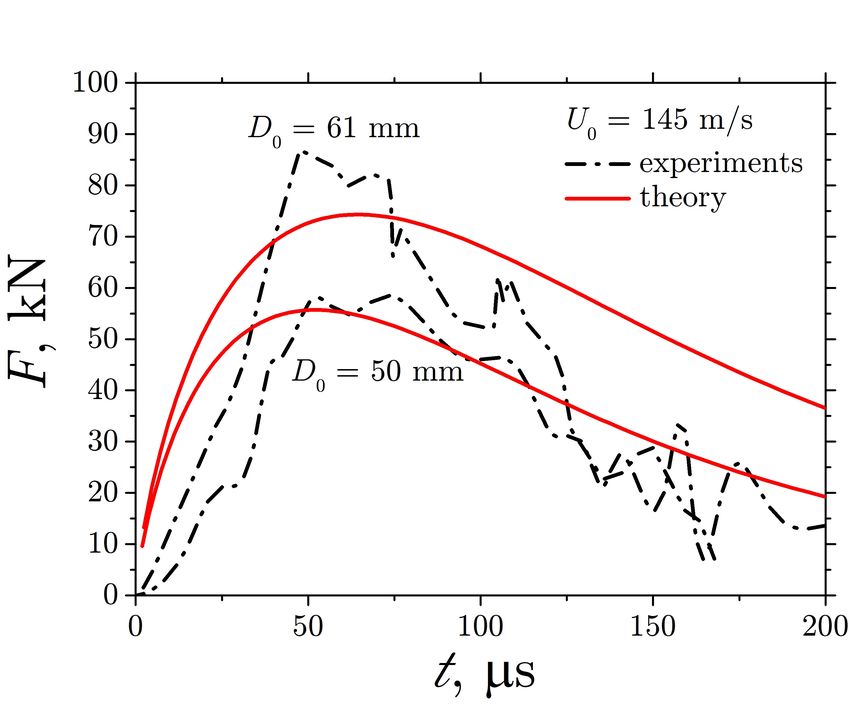
A PREPRINT - J ULY 16, 2020

a presence of a liquid phase), or sintering in some cases, can cause a catastrophic defluidisation [26, 27]. Collision
phenomena, including coagulation, rebound, and fragmentation, are also important physical processes controlling the
dynamics of Saturn’s rings [28, 29] or formation processes of satellites and planets in the outer Solar System [30].
Many existing theoretical approaches to the modeling of the impact, deformation and penetration of solid bodies are
based on the hydrodynamic theories [31–37]. Such models are often based on a kinematically admissible flow, which
satisfies the continuity equations, the boundary conditions and the momentum balance conditions in a simplified form,
for example in integral form of in certain regions of the deforming media. Such models are able to successfully predict
integral parameters of the problem, like penetration depth, projectile deformation, its residual velocity after penetration
of a finite target.
Approximate model of deformation of a long plastic rod has been developed in [38]. The model is based on the
assumption that the rod is deformed by the propagation of a plastic wave, generated by impact onto a perfectly rigid
target. Similar ideas have been applied in [39, 40] for the description of deformation and breakup of an ice particle.
However, these simplified approaches are not sufficient to model the processes of particle fragmentation or heat transfer.
For such advanced modeling some details of the velocity field in the deforming particle are required [41].
The main objective of this study is the theoretical model for deformation of a plastic particle during its collision with
a perfectly rigid target. The flow in the particle is approximated by an instantaneous potential flow past a disc. The
disc in the model is associated with the circular spot of the deforming particle and the rigid substrate. In the plastic
flow in the particle the yields strength Y is a function of the effective strain rate. Such material behaviour is typical to
quasi-brittle ice crystal particles [42]. The momentum balance equation is solve in the proximity to the particle impact
axis. The stress field in the deforming particle allows to estimate the total contact force and to predict evolution of the
particle deformation. The predicted evolution of the force applied to the target by an impacting ice particle agrees well
with the experimental data existing in the literature.

2   Flow field in the deforming particle

The flow field in a particle deforming by a collision with a rigid target is determined by the material properties of the
ice, like yield strength Y , elastic shear modulus G, density. The flow can be also influenced by the developments of
cracks leading to the particle fragmentation. Nevertheless, in many cases a simplified kinematically admissible flow
can be a rather good approximation for the velocity field in the particle, especially if the inertial effects in the flow
are dominant. Such approach is useful for the description of the velocity fields in the penetration mechanics [37]. In
this study a flow in the deforming particle is approximated by an incompressible potential flow, associated with the
axisymmetric flow around a thin disc. The assumption of the particle incompressibility is valid for the impact velocities
much smaller that the speed of sound in ice. The speed of sound for pressure waves at −10◦ C is 3865 m/s, which is
much higher than the typical impact velocities of 100 m/s relevant to the aircraft applications.
Consider a cylindrical coordinate system {r, θ, z} with the corresponding base unit vectors {er , eθ , ez }. The flow field
in the deforming particle is approximated by the flow around a flat disc of the radius a, where a is the instantaneous
radius of the impression. The velocity potential for this flow relative to the wall is obtained from the well-known
solution [43] in the form

                                         2aU
                                             cos η sinh ξ cot−1 (sinh ξ) − 1 − U z,

                                    φ=                                                                                    (1)
                                          π

where ξ, η are dimensionless elliptic coordinates defined through


                                                              −1       z + ir
                                               ξ + iη = sinh                        .                                     (2)
                                                                         a

This velocity satisfies the impenetrability conditions at the solid substrate z = 0, r < a. The velocity field at the infinity
approaches to the uniform flow uz = −U .

                                                              2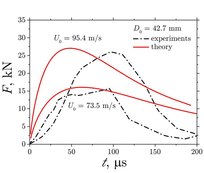
A PREPRINT - J ULY 16, 2020
Equation (2) allows to explicitly derive the expressions for the coordinates in the cylindrical system
(z + S cos β)2 + (r + S sin β)2
1
ξ = ln (3a)
2 a2
r + S sin β
η = tan−1 (3b)
z + S cos β
1/4
S = 4r2 z 2 + (a2 − r2 + z 2 )2
, (3c)
1 −1 2rz
2 tan z2 +a2 −r2
if r2 < z 2 + a2
β = 1 −1 2rz π
if r2 > z 2 + a2 (3d)
2 tan z 2 +a2 −r 2 + 2
π
if r2 = z 2 + a2
2
The components of the velocity field in the cylindrical coordinate system can be now obtained from the potential
function
u = ∇φ = (φ,ξ ξ,r + φ,η η,r )er + (φ,ξ ξ,z + φ,η η,z )ez . (4)
2.1 Velocity field in the vicinity of the impact axis
The velocity components can be obtained from (4) with the help of (1)-(3d). Near the axis the expressions for the
velocity components can be reduced to
" 3 #
2a3 rU r
ur = U 2 +O a3
(5a)
π (a2 + z 2 )
" 3 #
2 cot−1 az
2az 4a3 r2 z r
uz = U − −1− 3 +O (5b)
π π (a2 + z 2 ) 2
π (a + z ) 2 a 3
The corresponding rate-of-strain tensor E is the symmetric part of the velocity gradient at the impact axis
γ̇ 4rz
E = er ⊗ er − 2 (er ⊗ e z + e z ⊗ er ) + eθ ⊗ eθ − 2e z ⊗ e z , (6)
2 a + z2
4a3 U
γ̇ = 2, (7)
π (a2 + z 2 )
p √
where the symbol ⊗ denotes the usual tensor product, and γ̇ ≡ 2/3 E : E is the equivalent rate of strain.
2.2 Dimensionless particle dislodging during impact
Let us introduce a dimensionless particle dislodging ζ(t) scaled by the particle initial radius R
1 t
Z
ζ= U (t)dt. (8)
R 0
The evolution of the particle height can be estimated by the numerical integration of the equation dh/dt = uz (z = h)
leading to
2 cot−1 ha
1 dh 2ah
= − − 1, (9a)
R dζ π π (a2 + h2 )
h = 2R, at ζ = 0. (9b)
It is known that in the case of impact of an inviscid drop the flow near the wall does not influence the outer flow. The
value of U is thus constant and the dislodging is reduced to the dimensionless time ζ = U0 /R, where U0 is the impact
velocity. Theoretically predicted shapes of the impacting particle, computed using the velocity field (4), is shown in
Fig. 1. These predictions do not account for the ejection of the lamella along the substrate. Nevertheless, the shapes are
very similar to the observed forms of the deforming liquid drop during its high-velocity impact onto a dry substrate.
In Fig. 2 the predicted particle dimensionless height h/R is shown as a function of ζ in comparison with the computations
of a liquid drop impacts with very high Reynolds and Weber numbers [44]. These computations are validated by
comparison with the numerous experimental data. The agreement between the present theory and the CFD computations
is rather good, although no adjustable parameters have been introduced in the theory.
3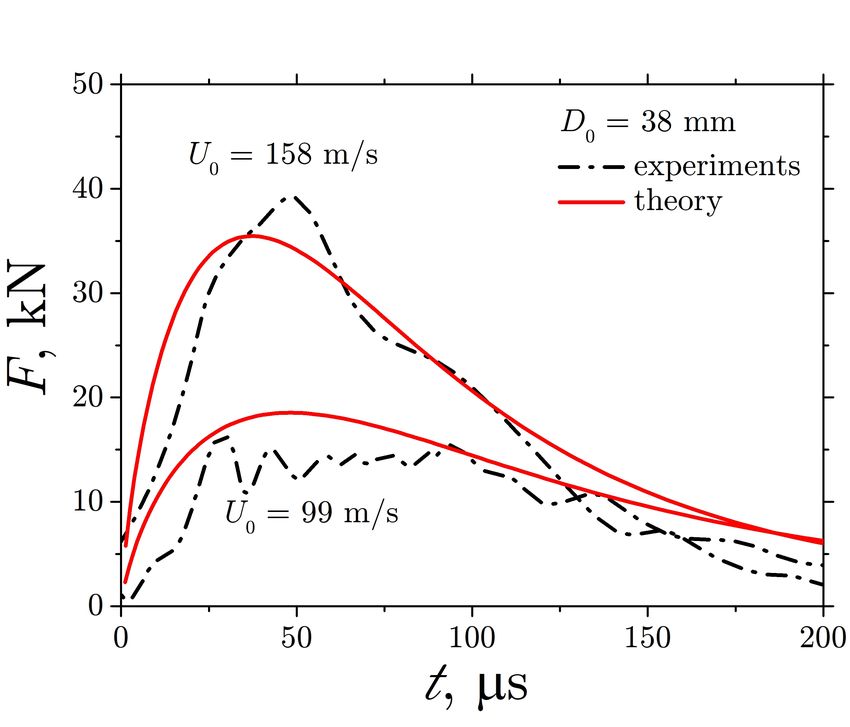
A PREPRINT - J ULY 16, 2020

Figure 1: Theoretically predicted dimensionless shapes of the impacting particle at different values of the dimensionless
displacement ζ.

Figure 2: Theoretically predicted dimensionless particle height h/R as a function of ζ, in comparison with the
computations for high-speed impact of a liquid drop [44].

                                                           4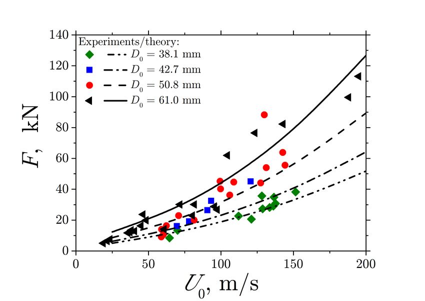
A PREPRINT - J ULY 16, 2020

3     Stress fields in the deforming plastic particle
3.1   Plastic stresses near the particle axis

The stress tensor in the particle is determined by the velocity field and by the yield strength Y
                                                                1/2
                                                     0     0      2          Y
                                       σ = −pI + σ , σ =                  √        E                                   (10)
                                                                  3         E:E
where p is the pressure and I is the unit tensor.
In this study the effect of the strain rate on the hardening of the particle material is taken into account. The material
hardening is an important property of the ice crystals [42]. This means the uniaxial yield strength is modeled in the
form:
                                                       Y = Y0 y(γ̇),                                                 (11)
where y is a dimensionless function of the the equivalent rate of strain γ̇, determined in (7) and Y0 is the static yield
strength at γ̇ → 0.
Near the particle axis, r → 0, the deviatoric part of the stress is obtained using (6) and (10) and further linearization it
for small r
                      0    Y                 4rz
                    σ =         er ⊗ er − 2         (er ⊗ ez + ez ⊗ er ) + eθ ⊗ eθ − 2ez ⊗ ez .                        (12)
                           3               a + z2
The momentum balance equation in the particle flow can be written in the form

                                          ∂φ ρ
                                   ∇ ρ        + ∇φ · ∇φ + p = ∇ · σ 0 .                                                (13)
                                          ∂t     2
where the divergence of the deviatoric stress at r → 0 is obtained from (12)
                                        "                                             #
                                    0       32Y0 a3 U z dy(γ̇)         8zY0
                              ∇·σ =                      3       −               y(γ̇) ez .                            (14)
                                           3π (a2 + z 2 ) dγ̇       3(a2 + z 2 )

Integration of (13) with the help of (14) yields
                                           2Y0 γ̇ y(γ̇)
                                                Z
                                   2Y                        ρ            ∂φ
                            p=−         +               dγ̇ − ∇φ · ∇φ − ρ    + f (t),                                  (15)
                                     3      3 γ̇(0) γ̇       2            ∂t
where f (t) is a function of time which has to be determined from the boundary conditions. The expression for the
pressure at the axis of the particle for the velocity potential defined in (1) is therefore
                                                   2Y (z) 2Y0 γ̇ y(γ̇)
                                                                  Z
                                  p = f (t) −             +                   dγ̇
                                                      3        3 γ̇(0) γ̇
                                           ρz h               z i dU         2ρz 2 U da
                                      −         π − 2 cot−1              −
                                            π                  a     dt     π (a2 + z 2 ) dt
                                                (                                     )2
                                           ρ 2 2 cot−1 az

                                                                        2az
                                      −      U                   −                −1                         (16)
                                           2            π           π (a2 + z 2 )

The function f (t) is determined from the condition at the rear tip of the particle z = h(t) where the normal stress
σzz = −p − 2Y (h)/3 vanishes:
                                          2Y0 γ̇(h) y(γ̇)
                                               Z
                             f (t) = −                     dγ̇                                                  (17)
                                           3 γ̇(0)     γ̇
                                                                            2ρh2 U da

                                        ρh                  h     dU
                                    +        π − 2 cot−1              +
                                        π                    a     dt    π (a2 + h2 ) dt
                                              (                                  )2
                                        ρ 2 2 cot−1 ha

                                                                    2ah
                                    +     U                   −              −1                                 (18)
                                        2            π          π (a2 + h2 )

                                                             5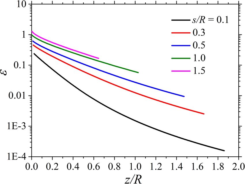
A PREPRINT - J ULY 16, 2020

Finally, the normal stress at the wall surface, z = 0, r = 0, is obtained from (16) and (18) in the form
                                             dU
                      −σzz = A(ζ)ρU              + B(ζ)ρU 2 + CY0 ,                                                   (19a)
                                             dζ

                                    h        2     −1   h
                          A =           1 − cot              ,                                                        (19b)
                                   R         π          a
                                                            (                                 )2
                                                   da 1 2 cot−1 ha

                                         2h2                                     2ah
                          B =                          +                   −              −1 ,                        (19c)
                                   πR (a2 + h2 ) dζ       2        π         π (a2 + h2 )
                                   2 γ̇(0) y(γ̇)
                                      Z
                          C =                     dγ̇.                                                                (19d)
                                   3 γ̇(h) γ̇
where A(ζ) and B(ζ) are dimensionless functions of the dimensionless particle dislodging ζ, and C is a dimensionless
function based on the distribution of the of the strain rates.

3.2   Momentum balance of an entire particle

Let us assume the total axial momentum of the deforming particle in integral form
                                                P (ζ) = πρR3 U K(ζ),                                                   (20)
where K(ζ) is a dimensionless function of ζ. The momentum balance equation
                                                     dP
                                                         ≈ πa2 σzz ,                                                   (21)
                                                     dt
can be rewritten with the help of (19a) and (20) in the form
                                    a2 A                        a2 B         a2 CY0

                                             dU            dK
                              K+ 2 U               +          + 2 U2 +              = 0.                               (22)
                                    R        dζ            dζ    R             R2 ρ
The momentum balance equation can be solved numerically if the dependence of the dimensionless particle axial
momentum K(ζ) is known. This function is determined from the consideration of a high-speed particle impact governed
exclusively by the inertial terms.
The effect of the elastic region in the deforming particle is neglected in this study since the strains in the particle grow
rather fast as soon the particle is deforming. The analysis of the elastic region is described in A, where the minor effect
of the elastic stresses is demonstrated.

4     High impact velocity approximation in the limit Y  ρU 2
In the case of very high impact velocity the effect of the yield stress can be much smaller than the inertia. Therefore the
terms associated with the yield strength in (22) can be neglected.
Moreover, since the inviscid is flow is disturbed only in a finite region near the wall of the size comparable with a, the
value of U far from the wall is assumed to be constant. The following expression for the axial momentum balance is
obtained from (22) for U (ζ) = U0
                                                 dK  a2 B
                                                    + 2          =   0.                                                (23)
                                                 dζ   R
                                                                     tU0
                                                            ζ    =       .                                             (24)
                                                                      R
                                                                                                                  √
The impression radius at early times can be roughly approximated by the radius of the truncated sphere a ≈ R 2ζ.
This assumption is confirmed by the numerous experimental data [46]. In Fig. 3 the theoretical predictions for B(ζ) are
compared with the CFD computations [44, 45] for the initial stage of a high Reynolds number impact of a liquid drop.
The agreement between the theory and the computations is rather good which means that the model accounts for the
main physical players. Note that no adjustable parameters have been used in the present theory.
Integration of the ordinary differential equation (23) subject the initial conditions K = 4/3 at ζ = 0, corresponding to
the axial momentum of a rigid sphere, yield the following expression for K(ζ) which can be reduced to
                                                            Z ζ
                                                      4
                                                K = −2           ζB(ζ)dζ.                                           (25)
                                                      3       0

                                                             6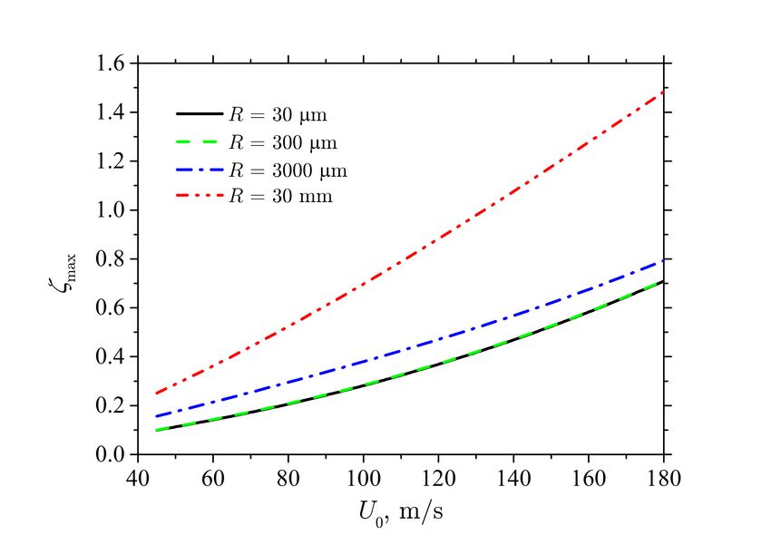
A PREPRINT - J ULY 16, 2020

Figure 3: Theoretically predicted dimensionless pressure B defined in (19c) as a function of ζ, in comparison with the
CFD computations [44, 45] of a high-speed liquid drop impact.

     Figure 4: Theoretically predicted dimensionless axial momentum K(ζ) defined in (25) as a function of ζ.

The computed values of the dimensionless axial momentum of the drop K(ζ) is shown in Fig. 4.
Note that the present solution is valid only for relatively small values of ζ. For long times ζ  1 the spreading of
the drop is governed by a radially expanding flow in a thin lamella. Such flow has been intensively studied in the
literature [37, 44, 47] and is out of the scope of this study.

5   Equations of motion of the deforming plastic particle

The governing equations of particle deformation can be now written in the dimensionless form using

                                    a   =   a(ζ)R,    h = h(ζ)R,         t = tR/U0 ,                             (26)
                                   U    =   U U0 ,   Y0 =   ρU02 Y   .                                           (27)

                                                          7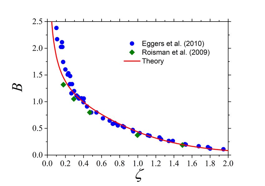
A PREPRINT - J ULY 16, 2020
√
Expression (22) in the dimensionless form is written assuming a ≈ 2ζ with the help of (26), (27) and (9)
dU 2ζCY
U = − . (28a)
dζ K + 2ζA
√
dh h 2g A
= − √ − , (28b)
dζ π ζ h
dt 1
= , (28c)
dζ U
where
2 −1 h
A ≡ h 1 − cot √ , (28d)
π 2ζ
2 2
h g 1 A 2hg
B ≡ √ + + √ , (28e)
2πζ 3/2 2 h π 2ζ
2ζ
g ≡ 2. (28f)
2ζ + h
The system of the ordinary differential equations (28) can be integrated numerically with the help of the solution of the
differential equation (9) for h and of the expression for the dimensionless axial momentum of the particle (25) subject
the initial conditions
ζ = 0, U = 1, h = 2, at t = 0. (29)
The total force produced by the particle impact on the target can be now evaluated in the form
2 CKY
Fz (ζ) ≈ −πa2 σzz = 2ζπρR2 U02 BU + (30)
K + 2Aζ
6 Results and discussion
The relation of the dependence of the yield strength on the strain rate can be estimated by examining the existing values
of the maximum impact force. For a perfectly plastic material the function y(γ̇) defined in (11) is constant, y = 1. But
this simplification is not sufficient for a reliable description of ice particle impact.
In this study we use the value for the static yield strength of the ice particle Y0 = 5.6 MPa determined in [42]. The
dimensionless evolution of the yield stress, defined in (11), is assumed in the form
y(γ̇) = 1 + χ − χ exp(−τ γ̇) (31)
which corresponds to the conditions
y(0) = 1, y(∞) → 1 + χ, (32)
which ensures finite stresses even at very high strain rates, typical to the very early stages of particle impact ζ
1. The
dimensionless constant χ and the characteristic time τ have to be determined from by the fitting with the experimental
data.
Integration of the expression (19d) for the function C with the help of (7) and (31) yields
2 √
4 2ζ + h 2χ 8 2τ U0 ζ 3/2 U
C = (χ + 1) ln + Ei −
3 2ζ 3 2 2
πR 2ζ + h
" √ #
2χ 2 2τ U0 U
− Ei − . (33)
3 πRζ 1/2
In Fig. 5 the theoretical predictions of the peak force computed using (30) is plotted as a function of the impact
velocity U0 in comparison with the experimental data from [42]. In all the computations the fitting values χ = 5.0
and τ = 0.0002 s are used. The agreement is rather good for various ice particle initial diameters D0 . Moreover, in
Fig. 6 the assumed dependence of the yield strength Y (γ̇) on the strain rate is compared with the estimations from
8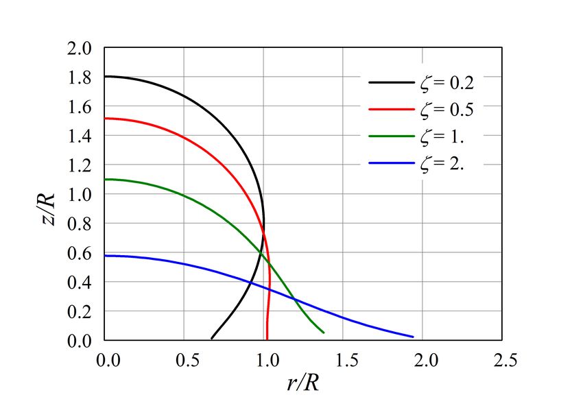
A PREPRINT - J ULY 16, 2020

Figure 5: Comparison of the experimental data from [42] for the peak force F with the theoretical predictions using
fitting values χ = 5. and τ = 0.0002 s.

Figure 6: Comparison of the data for the yield strength Y from [48] with the assumed approximated function (11) used
in (31) the values χ = 5. and τ = 0.0002 s obtained from the data for the maximum force, shown in Fig. 5.

                                                         9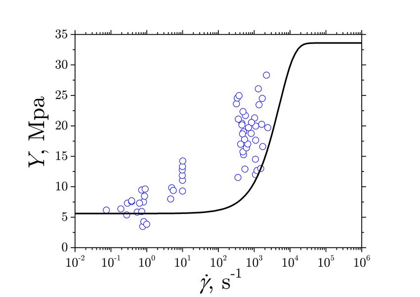
A PREPRINT - J ULY 16, 2020
Figure 7: Theoretically predicted force evolution F (t) in comparison with the experimental data from [49].
Figure 8: Theoretically predicted force evolution F (t) in comparison with the experimental data from [48].
the full CFD computations [48]. The values of the yield strength are of the same order despite the fact that a very
simplified model is used in this study. It should be noted that the form (31) is chosen accounting for the possibility of
the derivation of the solutions for the stresses in an explicit form. We have also tried to minimize the number of the
fitting parameters. Generally any form of the function y(γ̇) can be used in the solution for different particle materials.
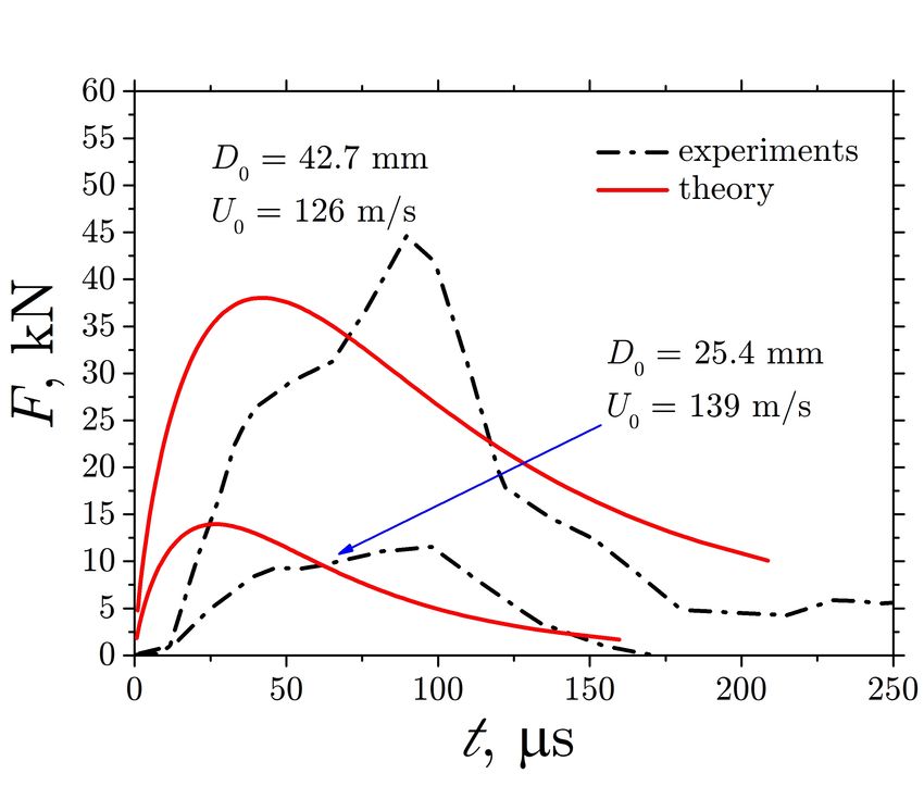
The theoretical predictions of the force F (t) computed using expression (30) are shown in Figs. 7 and 8 in comparison
with the experimental data from [49] and [48], respectively. In all the cases the theory allows to predict rather well
the peak value and the order of magnitude of the contact duration. In Fig. 7 the predicted time corresponding to the
force peak is slightly underpredicted. As already mentioned in [49] this delay can be explained by the not perfectly
spherical shape of the ice particle which leads to the difficulties in the precise determination of the instant of contact.
Moreover, the target used in the experiments, which is a carbon/epoxy composite panel, can be deflected by particle
impact if the impact velocity is high enough. The possible target deformation and damage can be evaluated using the
forces predicted by this theory, however their effect on the particle deformation is not yet accounted for.
The predictions in Fig. 8 agree with the experimental data much better than in Fig. 7. The initial instant in the
experiments shown in the graph in Fig. 8 is defined by the inception of the rise of the measured force.
10A PREPRINT - J ULY 16, 2020
Figure 9: Theoretically predicted maximum dimensionless particle dislodging ζ as a function of the impact velocity U0
for various particle radii R.
In some cases the theory slightly overpredicts the value of the contact force at the later stages of drop deformation after
the force reaches the maximum value. This overprediction can be explained by the particle fragmentation. The effect of
the particle fragmentation on the value of the effective yield strength is not considered in this theoretical model.
The value of the maximum dimensionless particle dislodging ζmax at which the particle velocity vanishes can serve as a
measure of the particle total deformation. The theoretically predicted values of ζmax are shown in Fig. 9 as a function
of the impact velocity for several particle initial radii. The value of ζmax is mainly determined by the impact velocity
U0 . However it reduces also for smaller particles. This effect is caused by the particle hardening for higher strain
rates, which are of order γ̇ ∼ U0 /R. For smallest particle sizes the dependence on the radius is only minor. However,
accurate experimental data with such relatively small particles are necessary for the confirmation of these predictions.
7 Conclusions
A theoretical model has been developed for the deformation of a spherical particle due to its normal collision with a
perfectly rigid target. The stress field in the deforming particle takes into account the hardening effects, namely the
increase of the yield strength Y on the local effective strain rate. This model is applied to the description of an impact
of ice crystal particle.
The model is based on the potential flow field around a thin disc. It satisfies the continuity and momentum balance
equations for initial stages of impact of an spherical particle. The momentum balance equations is solved in the vicinity
of the impact axis. The obtained stress at the target interface is used for the estimation of the total force.
In the limit Y = 0 the flow is reduced to the flow in spreading inviscid drop. The theoretical predictions for the
evolution of the drop height in time and for the evolution of the pressure at the substrate agree very well with the
existing computational results for drop impact with very high value of the Reynolds and Weber numbers.
The dependence of the yield strength Y on the local strain rate is estimated by the fitting of the theoretical predictions
for the maximum force with the experiments. Finally, the model is applied for the prediction of the time evolution of
the force. The theoretical predictions agree rather well with the experiments data for various particle impact velocity
and initial diameter. This indicates that the theory is able not only to predict the total force but also to estimate the
characteristic time of collision process and the characteristic strain rate. These results indicate that the approach in this
study can be potentially applied to the prediction of the heat transfer during collision. The flow field can be used for the
description of the particle fragmentation.
11A PREPRINT - J ULY 16, 2020
Acknowledgement
The funding received within the European Union’s Horizon 2020 research and innovation program under grant agreement
MUSIC-haic-767560 is gratefully acknowledged.
References
[1] T. C. Currie, D. Fuleki, and A. Mahallati, Experimental studies of mixed-phase sticking efficiency for ice crystal
accretion in jet engines, in 6th AIAA Atmospheric and Space Environments Conference, p. 3049, 2014.
[2] J. G. Mason, P. Chow, and D. M. Fuleki, Journal of engineering for gas turbines and power 133 (2011).
[3] T. Currie, P. Struk, J.-C. Tsao, D. Fuleki, and D. Knezevici, Fundamental study of mixed-phase icing with
application to ice crystal accretion in aircraft jet engines, in 4th AIAA Atmospheric and Space Environments
Conference, p. 3035, 2012.
[4] A. J. Bucknell et al., Experimental studies of ice crystal accretion on an axisymmetric body at engine-realistic
conditions, in 2018 Atmospheric and Space Environments Conference, p. 4223, 2018.
[5] C. Saunders and S. Peck, Journal of Geophysical Research: Atmospheres 103, 13949 (1998).
[6] J. P. Veres and P. C. Jorgenson, Modeling commercial turbofan engine icing risk with ice crystal ingestion, in 5th
AIAA Atmospheric and Space Environments Conference, p. 2679, 2013.
[7] E. Ayan, S. Ozgen, C. Murat, and E. Tarhan, Prediction of ice crystal accretion with TAICE, in SAE 2015
International Conference on Icing of Aircraft, Engines, and Structures, SAE Technical Paper 2015-01-2148, 2015.
[8] J. Veres, P. Jorgenson, and W. Wright, A model to assess the risk of ice accretion due to ice crystal ingestion in a
turbofan engine and its effects on performance, in 4th AIAA Atmospheric and Space Environments Conference, p.
3038, 2012.
[9] R. S. Mazzawy, Modeling of ice accretion and shedding in turbofan engines with mixed phase/glaciated (ice
crystal) conditions, in 2007 SAE Aircraft and Engine Icing International Conference, SAE Technical Paper
2007-01-3288, 2007.
[10] J. Löwe et al., Journal of Physics: Conference Series 745, 032013 (2016).
[11] T. Hauk, Investigation of the impact and melting process of ice particles, PhD thesis, Technische Universität
Darmstadt, 2016.
[12] S. Antonyuk, S. Heinrich, N. Deen, and H. Kuipers, Particuology 7, 245 (2009).
[13] B. Crüger et al., Particuology 25, 1 (2016).
[14] F. Gollwitzer, I. Rehberg, C. A. Kruelle, and K. Huang, Physical Review E 86, 011303 (2012).
[15] B. J. Mullins, I. E. Agranovski, and R. D. Braddock, Aerosol Science & Technology 37, 587 (2003).
[16] J. Fu, G. K. Reynolds, M. J. Adams, M. J. Hounslow, and A. D. Salman, Chemical Engineering Science 60, 4005
(2005).
[17] S. Brulin, C. Tropea, and I. V. Roisman, Colloids and Surfaces A: Physicochemical and Engineering Aspects 587,
124271 (2020).
[18] C. Weickgenannt, I. V. Roisman, and C. Tropea, New Journal of Physics 17, 083059 (2015).
[19] B. Qian and K. S. Breuer, Journal of Fluid Mechanics 666, 554 (2011).
[20] K. Curran, S. Colin, L. Baldas, and M. Davies, Microfluidics and Nanofluidics 1, 336 (2005).
[21] C. Saunders, Journal of Applied Meteorology 32, 642 (1993).
[22] I. Brooks, C. Saunders, R. Mitzeva, and S. Peck, Atmospheric research 43, 277 (1997).
[23] L. Vardiman, Journal of the Atmospheric Sciences 35, 2168 (1978).
[24] D. M. Murphy et al., Aerosol science and technology 38, 401 (2004).
[25] G. Reynolds, J. Fu, Y. Cheong, M. Hounslow, and A. Salman, Chem. Eng. Sci. 60, 3969 (2005).
[26] D. Geldart, Powder Tech. 6, 201 (1972).
[27] S. J. Antony, W. Hoyle, and Y. Ding, editors, Granular materials: fundamentals and applications (Royal Society
of Chemistry, Gateshead, Tyne and Wear, UK, 2004).
[28] M. Higa, M. Arakawa, and N. Maeno, Icarus 133, 310 (1998).
12A PREPRINT - J ULY 16, 2020
[29] K. D. Supulver, F. G. Bridges, and D. Lin, Icarus 113, 188 (1995).
[30] M. Kato et al., Icarus 113, 423 (1995).
[31] Z. Rosenberg, E. Marmor, and M. Mayseless, International Journal of Impact Engineering 10, 483 (1990).
[32] A. Tate, International Journal of mechanical sciences 28, 599 (1986).
[33] I. Frankel and D. Weihs, Journal of Fluid Mechanics 216, 213 (1990).
[34] J.-f. Lou et al., Defence Technology 10, 239 (2014).
[35] A. Seguin, Y. Bertho, P. Gondret, and J. Crassous, Physical review letters 107, 048001 (2011).
[36] C. E. Anderson Jr, International Journal of Impact Engineering 108, 3 (2017).
[37] A. L. Yarin, I. V. Roisman, and C. Tropea, Collision Phenomena in Liquids and Solids (Cambridge University
Press, 2017).
[38] G. I. Taylor, Proceedings of the Royal Society of London. Series A. Mathematical and Physical Sciences 194, 289
(1948).
[39] T. Hauk, E. Bonaccurso, I. V. Roisman, and C. Tropea, Proc. R. Soc. A 471, 20150399 (2015).
[40] I. Roisman and C. Tropea, Proceedings of the Royal Society A: Mathematical, Physical and Engineering Sciences
471, 20150525 (2015).
[41] A. L. Yarin, I. V. Roisman, K. Weber, and V. Hohler, International Journal of Impact Engineering 24, 171 (2000).
[42] J. D. Tippmann, H. Kim, and J. D. Rhymer, International Journal of Impact Engineering 57, 43 (2013).
[43] G. K. Batchelor, An Introduction to Fluid Dynamics (Cambridge University Press, 1967).
[44] I. V. Roisman, E. Berberović, and C. Tropea, Physics of fluids 21, 052103 (2009).
[45] J. Eggers, M. A. Fontelos, C. Josserand, and S. Zaleski, Physics of Fluids 22, 062101 (2010).
[46] R. Rioboo, M. Marengo, and C. Tropea, Experiments in fluids 33, 112 (2002).
[47] A. Yarin and D. Weiss, Journal of fluid mechanics 283, 141 (1995).
[48] J. D. Rhymer, Force criterion prediction of damage for carbon/epoxy composite panels impacted by high velocity
ice, PhD thesis, UC San Diego, 2012.
[49] H. Kim and K. T. Kedward, AIAA journal 38, 1278 (2000).
A Elastic region of the particle
The strain tensor ε in the elastic region can be estimated through
dε
= E. (34)
dt
The strain tensor can be expressed using (5b)-(34)
ε = ε(er ⊗ er + eθ ⊗ eθ − 2ez ⊗ ez ), (35a)
dε 2Ra3
= 2, (35b)
dζ π (a2 + z 2 )
2 cot−1 az
1 dz 2az
= − − 1, (35c)
R dζ π π (a2 + z 2 )
The impression radius a = a(ζ) is determined only by ζ and the initial shape of the particle.
The elastic-plastic boundary can be now determined from the yield condition
√
G 6ε · ε = Y, (36)
where G is the shear modulus of ice particle. This condition at the axis yields
Y
ε= . (37)
6G
For a spherical
p particle of radius R, the coordinate z = z ? of the elastic-plastic boundary is obtained using the relation
a = R 1 − (1 − ζ)2 . In Fig. 10 the computed values of the strain ε at the particle axis are shown for various s. Since
for ice Y /G ∼ 10−3 already at relatively small particle displacements the particle is completely plastic.
In the further analysis for very high impact velocities leading to significant particle deformation the effect of the
elasticity at the initial stage is neglected.
13A PREPRINT - J ULY 16, 2020
Figure 10: Evolution of the strain ε along the particle axis.
14You can also read