Development of Bladeless Thruster for an UAV Application - Journal of Emerging Technologies ...
←
→
Page content transcription
If your browser does not render page correctly, please read the page content below
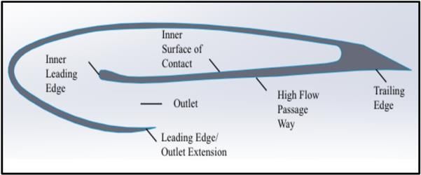
© 2020 JETIR May 2020, Volume 7, Issue 5 www.jetir.org (ISSN-2349-5162)

 Development of Bladeless Thruster for an UAV
 Application
 1
 Anutha M A, 2Aparna Ravi, 3Arun Luke Dsouza, 4Sunil Kumar, 5Tejaswini G
 1
 Assisstant Professor, 2,3,4,5Student
 1,2,3,4,5
 Department of Aeronautical Engineering,
 1,2,3,4,5
 Dayananda Sagar College of Engineering, Shavige Malleshwara Hills, Kumaraswamy Layout, Bangalore -78.

Abstract : Conventional multi-copters include a plurality of propellers designed to provide lift, propulsion and altitude control of
the UAV. Inspired by the Dyson bladeless fan, the proposed thruster has the significant advantage of a bladeless technology in
terms of safety. The thruster is composed of a vertical inlet duct with an Electric Ducted Fan and a special nozzle ring. The pressure
difference created through the airfoil-like cross-section of the ring combined with the Coanda effect helps to create at a thruster that
has no externally rotating blades or propellers.

Index Terms - Bladeless thruster, Coanda effect, entrained air, induced air.
 I. INTRODUCTION
 The idea of a Bladeless Thruster system was inspired by the British tech manufacturer Dyson when they released
merchandise called the Air Multiplier – a quieter fan, more power-efficient, safer and most importantly ‘bladeless’. The mechanism
of the thrusters employed will be composed of two parts – an Electric Ducted Fan (EDF) or a specifically designed compressor and
a discharge frame.

 The purpose of the electronic components is to provide a form of suction of air from the surroundings and channel it towards
the discharge frame. The discharge frame is held in position to accelerate the incoming flow. Similar concepts of pressure differences
over the surface of the airfoil are employed across the nozzle ring. The induced airflow through the suction mechanism creates a
region of low pressure over one end of the ring. The combination of the induced flow and the accelerated flow creates a high-pressure
area across the other end of the ring. The fundamentals used here are basic concepts of lift generation and thus it can be employed in
creating a propulsion system that creates a state-of-the-art bladeless design on an Unmanned Aerial Vehicle (UAV).
 II. EXPERIMENT DETAILS
 2.1 Feasibility of Bladeless Thruster
 Referring to various research papers, the ideology of a bladeless propulsion system was conceived through Dyson’s bladeless
fan. Based on the research by Daniel Valdenegro et al [1] the thruster assembly is composed of two parts -an EDF or a compressor
and a discharge frame with an inlet. The EDF will provide high velocity or high-pressure air to the discharge frame, which in turn
creates a suction of air termed as induction [2] through the discharge frame. The surrounding air is drawn into the injected flow and
is termed as entrainment [2]. Here, fundamental concepts of lift are involved that creates a low-pressure on the suction surface of the
airfoil and a high-pressure on the pressure surface of the airfoil.

 The induced airflow creates a low-pressure area on the periphery of the ring. The combination of induced airflow and
injected airflow create a high- pressure area in the component. the fundamental concept of low- and high- pressure areas for creating
lift are employed. This concept of a propulsive system can be applied to create the first start of the art bladeless UAV [7]. A change
in pressure from the inlet and outlet is necessary to create thrust from a propulsion system. A net change of pressure in the flow
causes an additional change in momentum.

 Fig.1. Airfoil Parts.

2.2 Thruster Cross-section
 In order to achieve a better performance, an airfoil profile Fig.1 was selected among standardized airfoils and evaluated as
the thruster’s cross-section, because it has a high curvature (good Coanda surface) [3]. Thus, an enhanced suction of air from the rear
portion of the discharge ring can be achieved. The airfoil like cross-section of the nozzle is essential to increase the performance of
the thruster. The airfoil can be modified to obtain maximum thrust by varying parameters like throat size, inlet duct length, hydraulic
diameter and taper angle. The capacity to acquire greatest thrust from each thruster necessitates a uniform flow (laminar) of air that
is not constrained by any horizontal flow components along its thrust axis (turbulence).

 Another important concept that needs to be understood completely in order to successfully design the thruster is the Coanda
effect and subsequently the Coanda ejector [4]. The Coanda ejector Fig.2 is an axisymmetric device that uses the injected primary
flow on the inward curved surface of the geometry while entraining a secondary flow on the outer curved surface. A Coanda ejector

JETIR2005257 Journal of Emerging Technologies and Innovative Research (JETIR) www.jetir.org 856
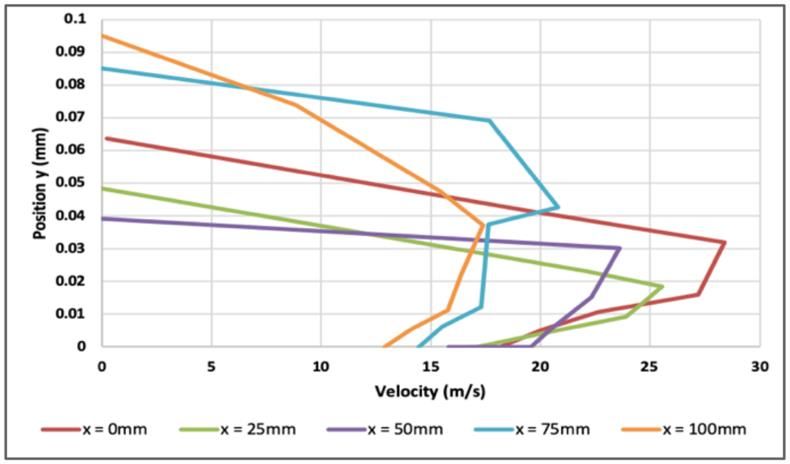
© 2020 JETIR May 2020, Volume 7, Issue 5 www.jetir.org (ISSN-2349-5162)
is primarily used to deliver a high ratio of the induced mass flow rate to the injected mass flow rate. The ratio of induced mass flow
rate to injected mass flow rate is called w factor [4].

 The primary flow is provided by a compressor, which follows the curved contour of the ejector after flowing through the
throat, due to Coanda effect. A turbulent mixing zone is developed as a result of expansion/compression waves created due to the
pressure at the outlet section. The effects of pressure ratio, outlet and ejector configurations on the system performance are estimated
based on the performance parameters. The mixing layer growth is crucial to enhance the performance of the Coanda ejector as it
controls the w factor and the mixing length. Based on the velocity profile shape Fig.3, which is measured by the amount of the
outlet throat gap, the mixing characteristics can be approximated. Complete mixing ratio between the primary and the secondary or
induced jets is indicated by the flattened shape of the profile. To yield a better ejector performance, these characteristics need to be
achieved in a section closer to the inlet.

 Fig.2. Coanda Ejector Surface.

 Fig.3. Velocity magnitude in five sections of the thruster.

2.3 Design of Thruster Cross-section
 The airfoil cross-section of the thruster has evolved primarily from Dyson’s bladeless fan’s cross- section. The best thruster
design was chosen after running a CFD 3D Analysis of the thruster. The cross-section design and analysis were done using
SolidWorks. A k-epsilon model was preferred as the required turbulence model [5]. SolidWorks 3D CAD data is directly used for
fluid flow simulation using SolidWorks Flow Simulation using built-in functions. The fluid domain is automatically generated
based on the geometry and is then revised for any design changes. Flow conditions are well-defined directly on the SolidWorks
CAD model.

 SolidWorks was chosen as it can easily handle our geometry containing constricted openings and sharp angles without the
need to defeature the model. SolidWorks Flow Simulation provides an exceptionally efficient automatic mesher for both fluid and
solid regions and boundaries with mesh refinement appropriate to geometrical or physical requirements. In SolidWorks Flow
Simulation the internal flow space containing the fluid is not modelled as a discrete domain in the design. This makes the 3D
analysis of the geometry easy.

 The first design chosen has a larger slit size with the intention of obtaining an increased mass flow rate at the expense of
loss of outlet velocity (Fig.4(a)). On analysis it was observed that the first design does not provide sufficient thrust as the outlet
velocity was too low. In order to overcome this drawback, a CD nozzle type arrangement Fig.4(b) was added to the outflow section
of the airfoil [5]. This helped in increasing the exit velocity, but it did not produce sufficient thrust. The third design Fig.4(c) was
created by decreasing the throat size to 3 mm and this design successfully provided the required thrust with uniform flow.

JETIR2005257 Journal of Emerging Technologies and Innovative Research (JETIR) www.jetir.org 857
© 2020 JETIR May 2020, Volume 7, Issue 5 www.jetir.org (ISSN-2349-5162)

 (a)

 (b)

 (c)

 Fig.4. (a) Design 1 (b) Design 2 (c) Design 3.

III. RESULTS AND DISCUSSION
3.1 Analysis of Bladeless Thruster
 The design conditions applied were based on the dimensions of the EDF available. A 64mm 4500 rpm EDF was chosen
for the study based on the availability. Hence, the inlet duct diameter was fixed at a diameter of 64mm. The maximum hydraulic
diameter of the thruster outlet was 200mm.Since mass flow rate is required as an inlet boundary condition during CFD analysis, it
was calculated using equation 1 and 2 as shown below

 3.14 × 4500 × 0.064
 = = = 15.08 / … … … … … … … … … … … … (1)
 60 60

 (0.064)2
 = = 1.225 × (3.14 × ) × 15.08 = 0.0594 / … … … … … (2)
 4

 Here, ‘v’ is velocity, ‘N’ is the rpm of the motor, ‘D’ denotes the diameter of the fan, ‘m’ represents the mass flow rate,
‘A’ is the area encompassed by the fan and ‘v’ in equation 2 is the velocity calculated from equation 1.

 The drawbacks of design 1 were that the exit mass flow rate obtained was very small and negligible and outlet velocity
obtained was much less than the inlet velocity. Hence, the thrust obtained was very small. The drawbacks of design 2, which was
designed with the aim of increasing both the mass flow rate and the velocity at the outlet by employing a convergent-divergent
passage at the exit of the airfoil, were that the mass flow rate obtained was nearly the same as that of the inlet but the velocity was
much less than that obtained at the outlet of design.

 The drawbacks of both design 1 and design 2 were overcome in design 3 with a throat size of 3mm Fig.4(c) and sufficient
thrust was obtained. In order to further compare the designs obtained, a few parameters were considered, the results of which are
described in the next section. The consolidated results of the 3D flow analysis of the three designs are as given in Table 1.

 Table 1: 3D flow analysis of the three designs.

 Design 1 Design 2 Design 3
 Mass Flow Rate at
 0.06 kg/s 0.06 kg/s 0.06 kg/s
 Inlet
 Velocity at Inlet 15.5 m/s 15.5 m/s 15.5 m/s
 Mass Flow Rate at
 0.00020 kg/s 0.061 kg/s 0.067 kg/s
 Outlet
JETIR2005257 Journal of Emerging Technologies and Innovative Research (JETIR) www.jetir.org 858

© 2020 JETIR May 2020, Volume 7, Issue 5 www.jetir.org (ISSN-2349-5162)
 Velocity at Outlet 5.27 m/s 4.61 m/s 27.17 m/s
 Thrust 0.93 N 1.21 N 2.75 N
 Thruster Mass
 0.10 kg/s 0.08 kg/s 0.29 kg/s
 Flow Rate
 Thruster Velocity 1.97 m/s 2.44 m/s 5.85 m/s

3.2 Simulations and Experimental Results
 The first parameter considered was the Throat Size which would control the two main contributing factors to thrust-
velocity and mass flow rate. It was observed that with a smaller throat size, the mass flow rate was slightly more than the inlet mass
flow rate. Also, the exit velocity at the outlet was high, thus giving a considerable amount of thrust. The Coanda effect takes place
effectively with a smaller size. The next parameter considered was the Length of the Inlet Duct. Two variants were tried in each
of the design. The first version was with an inlet duct length was 30 mm, which means that the EDF was placed far away from the
thruster ring. The second case was where the EDF was placed close to the thruster ring, where the duct length was 10mm. It was
observed that placing the EDF closer to the ring helps generate a more uniformly distributed flow at the exit of the thruster. When
the EDF was placed far from the ring, greater outflow was observed from the top of the ring and almost no flow was obtained from
the bottom of the ring (the section near the inlet).

 Another parameter analysed was the Taper Angle of the ring cross-section. A taper angle of 15o and 20o was chosen for
the study. It was seen that the taper angle does not contribute significantly to the final thrust obtained. Hence no taper angle was
chosen for the final design in order to reduce constraints and restrictions on manufacturing.

 The next parameter chosen for analysis was Hydraulic Diameter. It was observed that the best results were obtained for
an optimum hydraulic diameter of 200mm. Increasing the hydraulic diameter to 300mm or 250mm produced a lower thrust, and
decreasing the hydraulic diameter to 150mm gave a non-uniform flow at the exit. The increment in mass flow rate is quite small
and negligible although the cross-sectional area increases as the hydraulic diameter increases. The details of the values obtained are
as shown in Table 2.

 Table 2: Values obtained for various Hydraulic Diameter.

 Hydraulic Diameter
 150mm 200mm 250mm 300mm
 Mass Flow
 0.06 kg/s 0.06 kg/s 0.06 kg/s 0.06 kg/s
 Rate at Inlet
 Velocity at
 26.39 m/s 15.22 m/s 15.2 m/s 15.467 m/s
 Inlet
 Mass Flow
 0.058 kg/s 0.059 kg/s 0.067 kg/s 0.066 kg/s
 Rate at Outlet
 Velocity at
 76.83 m/s 44.98 m/s 27.17 m/s 19.87 m/s
 Outlet
 Thrust 6.04 N 3.61 N 2.75 N 2.248 N
 Thruster Mass
 0.285 kg/s 0.306 kg/s 0.296 kg/s 0.267 kg/s
 Flow Rate
 Thruster
 16.0 m/s 9.55 m/s 5.875 m/s 3.796 m/s
 Velocity

 (a)

JETIR2005257 Journal of Emerging Technologies and Innovative Research (JETIR) www.jetir.org 859

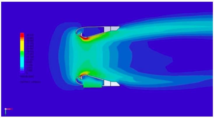
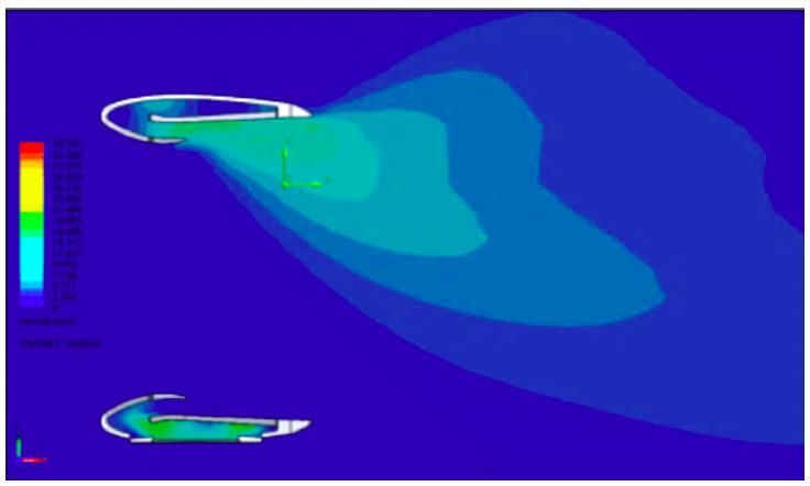
© 2020 JETIR May 2020, Volume 7, Issue 5 www.jetir.org (ISSN-2349-5162)

 (b)

 (c)

 Fig.5. Velocity Cut-Plot of (a)Design 1 cross-section (b)Design 2 cross-section (c)Design 3 cross-section with 200mm Hydraulic Diameter.

 The velocity contours for the three different cross-sections are as shown in Fig.5 (a), (b) and (c). It is observed that Design
2 gives a symmetric flow at the exit, but thrust produced is very low. Hence, Design 3 is considered to be the most apt design for
our thruster.

 The next parameter analysed was the position of the inlet duct. In previously conducted analysis, the inlet duct was placed
at the centre of the ring thruster. Considering a forward position that is closer to the leading edge resulted in a lower thrust, but an
aft position, i.e. near the trailing edge shows a slight increase in thrust. The results are as shown in Table 3.

 Table 3: Values obtained for various position of the inlet duct

 Position of Inlet Duct
 Aft Forward
 (near trailing Centre (near leading
 edge) edge)
 Mass Flow
 0.06 kg/s 0.06 kg/s 0.06 kg/s
 Rate at Inlet
 Velocity at
 14.7 m/s 15.47 m/s 15.27 m/s
 Inlet
 Mass Flow
 0.066 kg/s 0.064 kg/s 0.067 kg/s
 Rate at Outlet
 Velocity at
 44.2 m/s 43.2 m/s 27.15 m/s
 Outlet
 Thrust 3.825 N 3.725 N 2.75 N
 Thruster Mass
 0.24 kg/s 0.25 kg/s 0.29 kg/s
 Flow Rate
 Thruster
 7.55 m/s 7.73 m/s 5.77 m/s
 Velocity

JETIR2005257 Journal of Emerging Technologies and Innovative Research (JETIR) www.jetir.org 860
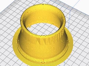
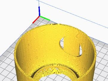
© 2020 JETIR May 2020, Volume 7, Issue 5 www.jetir.org (ISSN-2349-5162)
IV. PROTOTYPING AND MANUFACTURING
 Fused deposition modeling (FDM) is an additive manufacturing (AM) process in which a physical object is created directly
from a computer-aided design (CAD) model using layer-by-layer deposition of a feedstock plastic filament material extruded through
a nozzle. FDM process was selected as it comes across as the most accessible and a cost efficient method to produce a prototype in
the required dimensions and size. Products manufactured using Fused Deposition Modelling technology are characterized by
technical indices like good tensile strength, flexural strength or impact resistance, as well as economic indices, such as manufacturing
time and amount of support and build material used. These indices make FDM ideal method to prototype the bladeless thruster UAV.

4.1 Software and Printer Used
 Cura is an open source 3D printer slicing application. It was created by David Braam who was later employed by Ultimaker,
a 3D printer manufacturing company, to maintain the software. Ultimaker Cura is used by over one million users worldwide, handles
1.4 million print jobs per week, and is the preferred 3D printing software for Ultimaker 3D printers, but it can be used with other
printers as well. Ultimaker Cura works by slicing the user’s model (CAD) file into layers and generating a printer specific g-code.
Once the g-code is generated, it can be sent to the printer for the manufacture of the physical model. Cura is compatible with most
desktop 3D printers, can work with files in the 3D formats such as STL, OBJ, X3D, 3MF also with image file formats such as BMP,
GIF, JPG, and PNG.

 Creality Ender 3 printer is a compact designed 3D printer with decent build volume of 220 x 220 x 250mm, a magnetic
bed, a power recovery mode, and a tight filament pathway.

4.2 Manufacturable Design Analysis
 The material used to prototype our thruster was PLA. In order to minimize the use of support structures, which would have
to be removed separately, the thruster ring was divided into 16 parts. The exploded view is as shown in Fig 6.

 Fig.6. Exploded view of Design 3 cross-section thruster with 16 parts.

 On actual manufacturing, a few inconsistencies and defects were found. The 16 parts did not mate with each other perfectly
and some gaps were found. The front, bottom and isometric view of the manufactured thruster is shown in Fig 7. It can be seen that
there are gaps in between which will allow the air to escape thus leading to loss in efficiency.

 Fig.7. 3D printed Design 3 cross-section thruster with 16 parts.

 A 100mm hydraulic diameter thruster was designed in order to make the model more compact and suitable for an UAV
application. As the air emerges from the ramp, it creates a circular low-pressure region that pulls in the air into the casing and
generates a thrust of nearly 6 N. The flow characteristic found in the 100mm hydraulic diameter thruster was similar, in fact, better
with a more uniform exit profile than the flow found in the 200 mm hydraulic diameter thruster. The comparison is as shown in
Table 4.

JETIR2005257 Journal of Emerging Technologies and Innovative Research (JETIR) www.jetir.org 861
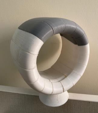
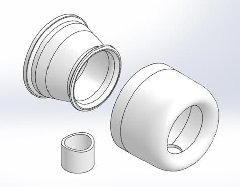
© 2020 JETIR May 2020, Volume 7, Issue 5 www.jetir.org (ISSN-2349-5162)
 Table 4: Comparison between 100mm and 200 mm Hydraulic Diameter Bladeless Thruster.

 Hydraulic Diameter
 100mm 200mm
 Mass Flow
 0.06 kg/s 0.06 kg/s
 Rate at Inlet
 Velocity at
 57.73 m/s 15.22 m/s
 Inlet
 Mass Flow
 0.04 kg/s 0.059 kg/s
 Rate at Outlet
 Velocity at
 65.36 m/s 44.98 m/s
 Outlet
 Thrust 6.16 N 3.61 N
 Thruster Mass
 0.13 kg/s 0.306 kg/s
 Flow Rate
 Thruster
 18.06 m/s 9.55 m/s
 Velocity

 In order to overcome the defects observed with the initial method of manufacturing, a new method was tried which proved
to be more efficient. The thruster was divided into three sections – the inlet, an outer shell and an inner shell. This helps remove the
gaps encountered in the previous method. Fig. 8 shows the three sections of the thruster to be manufactured.

 The bladeless thruster’s inner shell is approximated to take 8 hours and 38 minutes weighting 51g, while the outer shell
is approximated to take 11 hours and 39 minutes weighting 65g and the print material as Polylactic Acid (PLA). Fig 9 (a) and(b)
shows the bladeless thruster as rendered on Cura software and Fig 10 shows the 3D printer prototype.

 (a) (b) (c)

 Fig.8. (a) Exploded view thruster cross-section - inlet section, the inner shell and the outer shell; (b) Bladeless thruster Inner shell & (c) Outer shell
 rendered on Cura software.

 Fig.10. 3D printed Prototype 2 Thruster with three components.

 V. SUSTAINABLE DESIGN
 Sustainable design refers to creating products that are beautiful, functional and cost effective while having a reduced impact
on the environment. Sustainable design is also an explosive trend which has even grown through recession slowed years. What we’ve
done is Qualitative Life Cycle Assessment (LCA) [6] using real industry average numerical data and this type of assessment is
referred to as a screening level LCA. So we’ve selected certain parameters and then we baseline these parameters. Next make some
changes against the baseline. Once changes are made in the model and graphs automatically update. We’ve used assembly
visualization to rank these parts in the order of decreasing environmental impact. We can see that the outer and inner shell are the
worst offenders.

JETIR2005257 Journal of Emerging Technologies and Innovative Research (JETIR) www.jetir.org 862
© 2020 JETIR May 2020, Volume 7, Issue 5 www.jetir.org (ISSN-2349-5162)

 Fig.11. Assembly Visualization and Component Environmental Impact

 Fig.11. Comparison between Baseline and Current Design

VI. RESULTS AND DISCUSSIONS
 The bladeless thruster designed was successfully analysed taking into consideration variations in geometric parameters like
Throat Size, Length of Inlet Duct, Taper Angle, Hydraulic Diameter and Position of Inlet Duct. Based on the 3D Flow analysis using
SolidWorks, a bladeless thruster that provides sufficient thrust was achieved as shown in Fig.10.The manufacturing and design
limitations have been identified through comparisons between computational and experimental data. Further probing must be carried
out on the nature of flow and its influence on the mixing region.

 The thruster performance was evaluated by solving mass, momentum and thrust equations by simulating the thruster inside
a cuboidal domain. The thrust produced may be further increased by increasing the inlet mass flow rate by using a higher powered
EDF or a compressor. The bladeless thruster so devised may be used for a UAV Application which would be greatly beneficial in
terms of safety. the successful completion of this project on time.

VII. ACKNOWLEDGEMENT
 The authors gratefully acknowledge Karnataka State Council for Science and Technology for sponsoring this Project (Grant
number 43S_BE_2087).

JETIR2005257 Journal of Emerging Technologies and Innovative Research (JETIR) www.jetir.org 863
© 2020 JETIR May 2020, Volume 7, Issue 5 www.jetir.org (ISSN-2349-5162)
REFERENCES
[1] Daniel Valdenegro, Austin Capunay, Daniel Gonzalez, Luis Rodolfo Garcia Carrillo, Pablo Rangel 2018, Improving Safety:
 Design and Development of a Bladeless Thruster for Autonomous Multicopters, DOI: 10.1109/ICUAS.2018.8453474.
[2] Hossein Afshin, Mohammad Jafari, Bijan Farhanieh, Atta Sojoudi, 2015, Numerical investigation of geometric parameter effects
 on the aerodynamic performance of a Bladeless fan.
[3] M. Jafari, H. Afshin, B. Farhanieh and H. Bozorgasareh, Numerical Aerodynamic Evaluation and Noise Investigation of a
 Bladeless Fan - Journal of Applied Fluid Mechanics, Vol. 8, No. 1, pp. 133-142, 2015.
[4] Alexandru Dumitrache, Florin Frunzulica, Tudor Ionescu, Coanda Effect On The Flows Through Ejectors and Channels -
 Scienific Research and Education in the Air Force, June 2018.
[5] Lasse C. M ̊ansson, Simon H. Traberg-Larsen, 2014, Flow Characteristics of the Dyson Air Multiplier.
[6] PRé Consultants “Sima Pro LCA software, Sustainability software for fact-based decisions” Retrieved from https://www.pre-
 sustainability.com/about-pre.
[7] Edgar Herrera, retrieved from https://www.yankodesign.com/2017/08/18/the-dyson-of- drones/ .

JETIR2005257 Journal of Emerging Technologies and Innovative Research (JETIR) www.jetir.org 864
You can also read