Humidity Simulation Status: progress and recap May 25, 2020
←
→
Page content transcription
If your browser does not render page correctly, please read the page content below
Humidity Simulation Status:
progress and recap May 25, 2020

M. Bhamjee a , P.T. Mafa b , S.H. Connell a , L. Leeuw     b   and D. Boye   a,b

a   University of Johannesburg (UJ),   b   University of South Africa (UNISA)

                                  Assisted by
                               Marco Oriunno     c

        c   SLAC National Accelerator Laboratory, Stanforf University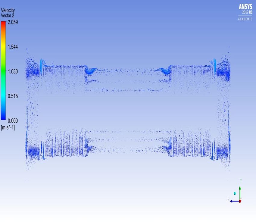
Brief Intro to CFD

• Governing Equations for fluid flow are:

                 ∂ρ
                    + ∇.(ρu) = 0                (1)
                 ∂t
 ∂(ρu)               ∂p
       + ∇.(ρuu) = −    + ∇.(µ∇u) + Bx + SM x   (2)
  ∂t                 ∂x
 ∂(ρv)               ∂p
       + ∇.(ρvu) = −    + ∇.(µ∇v) + By + SM y   (3)
   ∂t                ∂y
 ∂(ρw)               ∂p
       + ∇.(ρwu) = −    + ∇.(µ∇w) + Bz + SM z   (4)
   ∂t                ∂z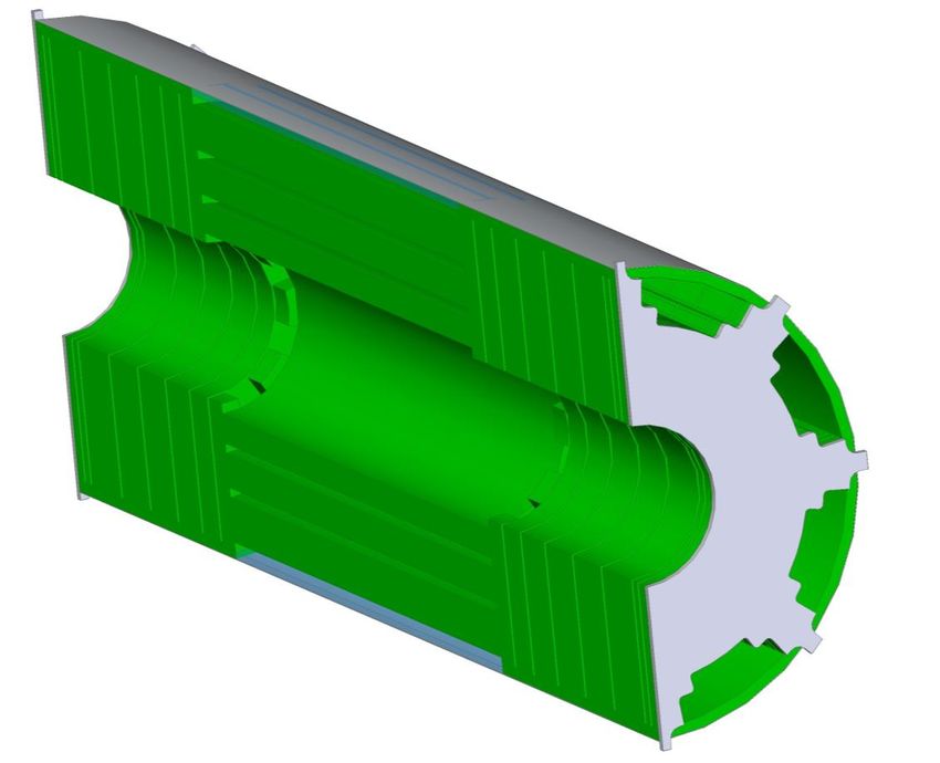
Brief Intro to CFD

• The above equations can be re-written in the form of a
  generalised scalar transport equation for the general
  transport variable named φ:

          ∂(ρφ)
                + ∇.(ρφu) = ∇.(Γ∇φ) + Sφ               (5)
           ∂t

• The aim in CFD is to solve this generalised scalar
  transport equation for the relevant transport variables
  in a problem
• The solution of such is done numerically
• The most common method is the Finite Volume
  Method (FVM) - Best for Fluid Flow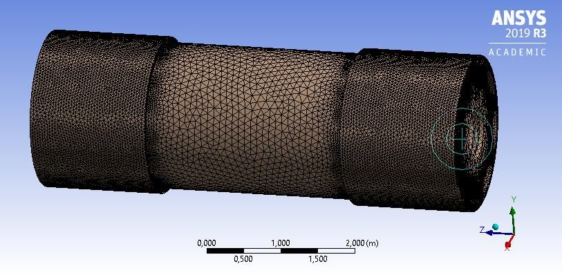
Brief Intro to CFD

• To execute the FVM the geometry (computational
  domain) is discretised into small computational cells as
  in the figure below
• This is referred to as the mesh
Brief Intro to CFD

• Thus, the genralised equation can be re-written for
  each cell as:

          Nf aces                Nf aces
∂(ρφ)      X                      X
      V +         ρf φf uf .Af =         Γf ∇φf .Af + Sφ V (6)
 ∂t
             f                    f

• Boundary conditions, initial conditions and transport
  properties are accounted for in the numerical solution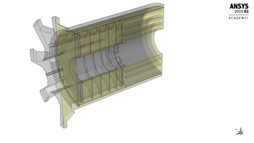
Aim of this Project

Research purpose of the simulations:
  • The Humidity Sensors planned for the ITK Upgrade
    are expensive and therefore optimisation of the number
    and placement of sensors are required;
  • Considering that their role could evolve from
    monitoring to interlock, consequently, the expected
    performance of the sensors needs to be well understood;
  • Include effect of different chemical species due to leaks
    and accidental events
  • Understand the spatial region protected by a sensor,
    location of dead spaces of low atmosphere renewal rates
    and timescales for the propagation of vapours from leak
    events to sensors.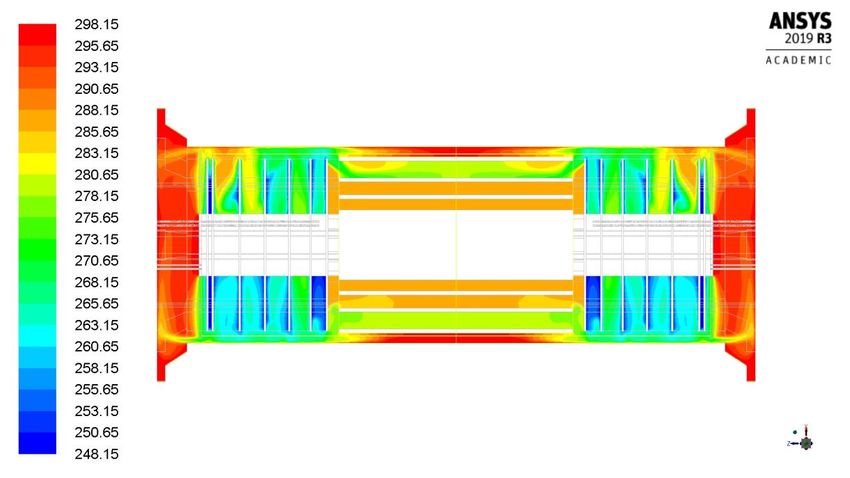
Aim of this Project

As part of this study:
  • Understand the need for local vs. global monitoring of
    the dewpoint inside the detector volume
  • Provide the simulations for temperature and humidity
    distribution inside the detector volume
  • Note that the detector will operate at a different temp
    over time, warmer at startup and colder in later years.
  • Will dewpoint requirements be unchanged - perhaps
    iterate over several scenarios to confirm.
  • Provide the final effective number and position of
    sensors. Verify that all constraints can be met (eg.
    Location colder than -20o C) - CFD can be used to
    decide.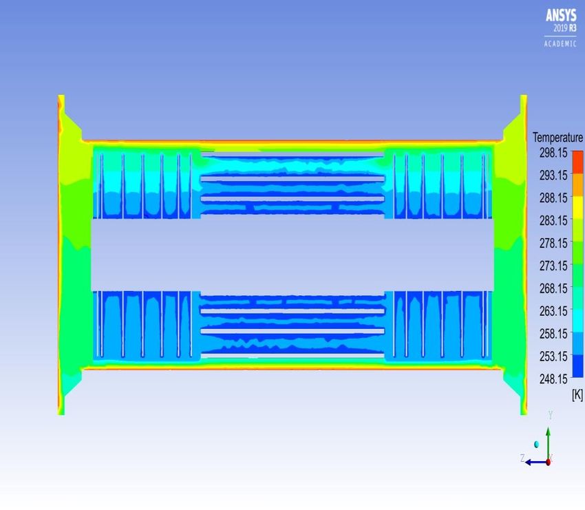
Progress Made and Challenges
             Faced

Progress made
  • Have a model that represents the SR1 case with all
    physics accounted for in the strips.

Challenges faced:
 • Meshing = week(s) of work - for small change
 • including new inlets/outlets/leaks requires geometry
    changes
 • Convergence is an issue but only for mass conservation
  • Issue where unrealistic humidities are being predicted
    in the OSV - needs further investigation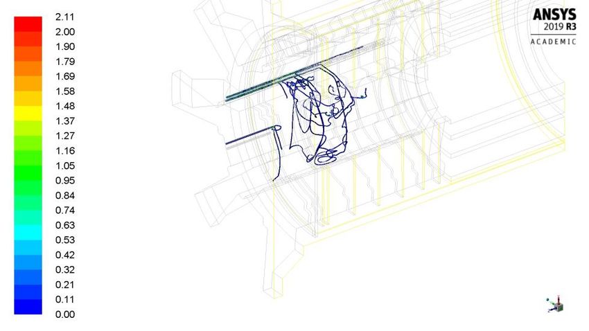
Progress Made and Challenges
             Faced

Steps In Progress (or to be taken) to resolve issues:
  • Introduce meshing schemes beyond tetrahedral meshing
  • Break up volumes into multi-zones (done)
  • Introduce Virtual Topology to repair issues - CAD
    model to a CFD Mesh (done)
  • Execute mesh
  • Test improved mesh for convergence
  • Look at modelling and numerics
  • Need to freeze geometry and model parameters to fix
    converegence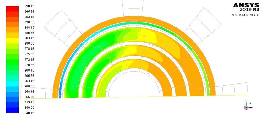
Progress Made and Challenges
             Faced

Steps In Progress (or to be taken) to resolve issues:
  • Latest progress annd results to follow in
    ”Backup” slides
Backup
Status update on the CFD humidity
                       modelling

                          PT Mafa2, M Bhamjee1, SH Connell1, L Leeuw2 and D Boye1,2
                               1. University of Johannesburg (UJ), 2. University of South Africa (UNISA)

                                                             Assisted by

                                                       Marco Oriunno3
                                3. SLAC NATIONAL ACCELERATOR LABORATORY, Stanford University

P Mafa Takisa: May 2020                       Status update on the CFD humidity modelling                  1
Status update on the CFD humidity modelling
Recap and progress
❖ Good convergence aspects (momentum (3D), mass transfer, heat flow and turbulence) on ITK
model with dry N2 flush only (SR1 Case 1 without leaks )
❖ Test leak species in simple tube scenario ( All working ).
❖ ITK model built (SR1 Case 2 with leaks ) : most issues are resolved except the convergence on
the mass continuity.
Need to get better Convergence for Mass continuity (currently 10^-3)
❖ Break the geometry in multiple bodies as shown in Figs. 1, 2 below and do a selective meshing
(selective meshing)
❖ Remesh using different technique depend on the geometry of different selected body , maximise
hexagonal mesh volume,
❖ worst case feel tetrahedral in minimum of zones and convert later into polyhedral
❖ The requirements for good quality of the mesh: skewness and aspect ratios to be less than 0.80
ideal 0.85 still accept and aspect ratio < 5, but may have to accept more < 20,
❖ So far, quality metrics, skewness is 0.82 and aspect ratios 9 for about half the geometry.
❖ Some remaining parts still require meshing (selective meshing) which can be finalised within a
day. And we should then test for improved convergence
P Mafa Takisa: 19 May 2020 Status update on the CFD humidity modelling 2Status update on the CFD humidity modelling ( Mesh Fig.1)
bulkhead
OSV
Strips-endcap
region
Strips-barrel
region
P Mafa Takisa: 19 May 2020 Status update on the CFD humidity modelling 3Status update on the CFD humidity modelling Recap and progress Need to get better Convergence for Mass continuity (currently 10^-3) ❖ If there are still problems, then need to look at modelling (physics) and numeric (algorithms) Other issue was 100% humidity in the OSV ❖ Not yet sure of the source of this ❖ Initialise it to 0%, it then iterates to a non-zero value ❖ Flow field not leading to this (checked) ❖ May have to check with the ANSYS developers (not uncommon) ❖ Dr Muaaz will contact Danie de Kok (Stephan Schmitt) Outstanding ❖ SR1 Case 2 - With Leaks as specified in previous presentation (adding leaks lead to problems ❖ Operation Case: Leaks @ 00C and dew point of -300C, Skin material - k = 50 W/mK ❖ Outlet set to obtain pressure drop of 4mbar P Mafa Takisa: 19 May 2020 Simplified model of species 4
Humidity Simulation Status: Geometry and
   Boundary Conditions Check, 2020

                       PT Mafa2, M Bhamjee1, SH Connell1, L Leeuw2 and D Boye1,2
                               1. University of Johannesburg (UJ), 2. University of South Africa (UNISA)

                                                             Assisted by

                                                       Marco Oriunno3
                                3. SLAC NATIONAL ACCELERATOR LABORATORY, Stanford University

Muaaz Bhamjee, Simon Connell
- 8 May 2020
                                                        N2 gas flushing concepts                           1
Status
Problem with changing Setup
1. Changes the require re-meshing
1. Changes in the geometry
2. Changes in the flushing scheme
2. Changes that are less arduous
1. Changes about temperatures at surfaces etc
Need to freeze, as makes a lot of work re-meshing and re-achieving convergence.
Current situation is have convergence except for mass concept
Also, OSV stubbornly has 100% humidity, whereas no humidity change is expected
• Navier Stokes approach is 4 eqns in 3D, Momentum and Mass flow, add Heat transfer + Turbulence
• Have 10-4 iteration-to-iteration for momentum and 10-6 iteration-to-iteration in energy (acceptable)
• However, for continuity (mass conservation) have 10-3, need improvement
On continuity, for momentum equations, expect solution is to improve meshing
• Introduce meshing schemes beyond tetrahedral meshing.
• Break up volumes into multi-zones (done)
• Introduce Virtual Topology to repair issues in going from a CAD model to a CFD Mesh (done)
• Execute mesh
• Test improved mesh for convergence
• Look at modelling and numerics as other sources of convergence issues.
• Iterate on the red parts.
Muaaz Bhamjee, Simon Connell
N2 gas flushing concepts 2
- 8 May 2020Status
ITk CFD Sim : ANSYS Fluent N2 flushing with air leak operational. Several requests
1. N2 inlets at the Bulkhead are drawn. Need further distribution of the N2 between the strip EC-disks.
2. Rel. humidity used in the plots/graphs. The dew-point is the figure of merit. Change plots to dewpoint.
3. Use ATLAS coordinate system, because this will led to mistakes. Swap XY
4. In a next iteration, make some detailed plots of the gradient of the stiffener disk. (At the moment there
are clearly problems with the boundary conditions.)
From Side 2 on are slide from ITk DCS Meeting of 7/3/2020. The previous slides referred before that.
Below is a summary of the decisions:
1. SR1 Case: Leaks as specified in slides
2. Operation Case: Leaks @ 00C and dewpoint of -300C
3. Skin material - k = 50 W/mK
4. Outlet set to obtain pressure drop of 4mbar
5. Set leaks to result in 1mbar overpressure
Then run three cases:
1. No Leaks with SR1 settings
2. Leaks - SR1
3. Leaks - Operation
We need to still look at potential options for benchmarking the model
– either humidity or temperature measurements from similar cases (preferably both), eg with ID
Muaaz Bhamjee, Simon Connell
N2 gas flushing concepts 3
- 8 May 2020Geometry and Boundary Conditions Check
Position of inlet tubes, outlet tube and leaks on the bulkhead.
Leak points via PP1
Feedthroughs
N2 Inlets
N2 Outlet
Muaaz Bhamjee, Simon Connell
N2 gas flushing concepts 4
- 8 May 2020Geometry and Boundary Conditions Check
New N2 Flushing Scheme Geometry and Model:
➢ N2 Inlets for full distribution via distributed manifold that distributes N 2 between the stiffener
disk and the detectors. Does not run into the barrel.
➢ N2 inlet between bulkhead and stiffener disk has been removed
➢ See adapted figure below as proposed by A.Korporaal-Nikhef-Amsterdam (Version: Sept.
11 2019).
Stiffener Disk
Bulkhead
N2 Inlet (this has been
Barrel removed as requested)
N2 Inlet (Distributed Manifold)
N2 Outlet
➢ Disks 0 – 5 are the detectors
Muaaz Bhamjee, Simon Connell
N2 gas flushing concepts 5
- 8 May 2020Geometry and Boundary Conditions Check
Blue arrows in Figure below illustrate inlet feeds between disks. Red arrow represents outlet.
Green arrows represent leaks
Muaaz Bhamjee, Simon
N2 gas flushing concepts 6
Connell - 8 May 2020Modelling of Species Transport in the ATLAS ITK
Boundary Conditions:
1. Inlets, Outlet and Leaks:
Boundary Type Mass Flow/ Temp (⁰C) Species Humidity
Velocity
Inlets (2 Uniform 2.4 m/s (per 15 N2 0%
manifolds) Velocity Inlet inlet tube)
Outlet Pressure Atmospheric Fluent Mixture – Fluent Calculated Fluent
Outlet Pressure Calculated Calculated
Leaks Mass Flow 0,0083333l/s 25 Air (composition - nitrogen 50-60%
Inlet per leak (12 (mass fraction of 0.78), oxygen
leaks total) (mass fraction of 0.21), water
vapour (mass fraction of 0.01).)
2. Walls:
Boundary Type Heat Transfer Conditions Temp (⁰C) Material
OSV Outer Wall Constant Temperature 25 Graphite
Wall
Detector Wall Constant Temperature -25 Graphite
Disks
Rest Wall Coupled Fluent Polymoderator and Skin – Glass
Calculated Inlet and outlet tubes - steel
Muaaz Bhamjee, Simon
N2 gas flushing concepts 7
Connell - 8 May 2020Modelling of Species Transport in the ATLAS ITK
Initial Conditions Conditions:
Zone Temp (⁰C) Species
Entire 15 N2
Domain
Muaaz Bhamjee, Simon
N2 gas flushing concepts 8
Connell - 8 May 2020Humidity Simulation Status: progress and
recap March 18, 2020
PT Mafa2, M Bhamjee1, SH Connell1, L Leeuw2 and D Boye1,2
1. University of Johannesburg (UJ), 2. University of South Africa (UNISA)
Assisted by
Marco Oriunno3
3. SLAC NATIONAL ACCELERATOR LABORATORY, Stanford University
PT Mafa : 17 March 2020 Model of species 9Modelling of Species Transport in the ATLAS ITK Aims ❖ implementation of the species model in the ITK geometry ❖ Presentation of the results ❖ Testing and fine tuning the model to improve the convergence PT Mafa : 17 March 2020 10
Modelling of Species Transport in the ATLAS ITK

  We introduced Leaks via PP1 feedthroughs @ a leak rate of 0.1 L/s air @ room temp –
  introduce near bulkhead

                                             Leak points via PP1
                                             Feedthroughs

                                                               N2 Inlets

                                                              N2 Outlet

PT Mafa: 17 March 2020                                                                  11
Modelling of Species Transport in the ATLAS ITK Model input ❖ The N2 being pump at the velocity of 2.4 m/s – originally 3 inlets @ 1.6m/s, the bottom inlet has been removed as requested. Thus, 2 inlets @ 2.4 m/s @ 15⁰C ❖ Humid air leaks entering the domain at a rate of 0.1/12 L/s (total leak rate) @ 25⁰C. ❖ We use air with three species: nitrogen (mass fraction of 0.78), oxygen (mass fraction of 0.21), water vapour (mass fraction of 0.01). Model setup We selected the Species transport model with mixture material: Nitrogen and air. the turbulence chemistry interaction is set to Eddy dissipation. We considered these options: inlet diffusion, diffusion energy source, full multicomponent diffusion and thermal diffusion PT Mafa: 17 March 2020 12
Modelling of Species Transport in the ATLAS ITK
 Results
 The most important parameters such: Relative humidity, Temperature and Velocity and are
 presented in the figures below.

 Relative Humidity [%] in the XZ - plane of OSV and Nitrogen volume (Pixel cylinder,
 Barrell and Endcap layers). High humidity profile in the OSV need to be investigated

                                                                     Low humidity in the
                                                                     range of [0 to 5%] with
                                                                     few dead zones

                                                                     High humidity regions
                                                                     with Humidity in the
                                                                     range of [25 to 30%]

PT Mafa : 17 March 2020                                                                        13
Modelling of Species Transport in the ATLAS ITK Results The relative humidity is presented in the figures below. Relative Humidity [%] in the YZ - plane of OSV and Nitrogen volume. PT Mafa : 17 March 2020 14
Modelling of Species Transport in the ATLAS ITK
   Results
   The relative humidity in the detector walls is presented in the figures below.

   Relative Humidity [%] in XYZ - plane of Walls of detector ( high humidity at the
   bottom region of walls in the range of [25 to 30%] )

PT Mafa : 17 March 2020                                                               15
Modelling of Species Transport in the ATLAS ITK
   Results
   The relative humidity is presented in the figure below. The humidity at the leak inlets is
   55%, Inlets 0% and Outlet 10%.

   Relative Humidity [%] in XY- plane of the OSV.

                                Outlet                          Inlets

                                                Leaks

PT Mafa : 17 March 2020                      Model of Species                                   16
Modelling of Species Transport in the ATLAS ITK
Results
The temperature is presented in the figure below.
Temperature [K] contours on XZ - plane
High temperature
region in the range of
[-6.85 ⁰C to 16.48 ⁰C]
Low temperature
region in the range of
[-25⁰C to -19.82 ⁰C]
PT Mafa: 17 March 2020
17Modelling of Species Transport in the ATLAS ITK
Results
The temperature is presented in the figure below.
Temperature [K] contours on YZ - plane
PT Mafa: 17 March 2020
18Modelling of Species Transport in the ATLAS ITK
Results
The temperature is presented in the figure below. Low temperature profile on the
left panel of Y- symmetry. Low
Temperature [K] contours on XY - plane
PT Mafa: 17 March 2020
19Model of species
Modelling in the
of Species ATLAS ITK
Transport in the ATLAS ITK
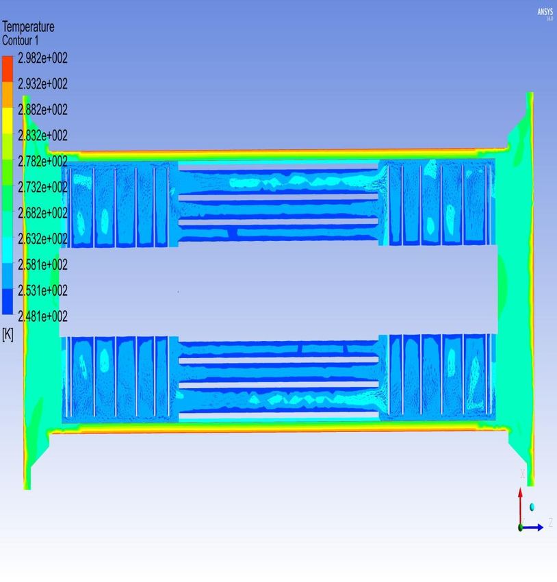
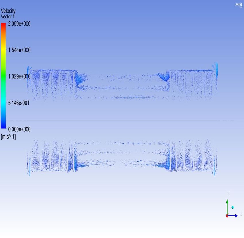
Results
The velocity is presented in the figures below. It is noted that a uniform velocity is seen in
the Nitrogen and OSV regions
Relative velocity [m/s] in XZ - plane
PT Mafa : 17 March 2020 20Modelling of Species Transport in the ATLAS ITK Results The velocity is presented in the figures below. It is noted that a uniform velocity is seen in the Nitrogen and OSV regions Relative velocity [m/s] in YZ - plane PT Mafa : 17 March 2020 21
Modelling of Species Transport in the ATLAS ITK

  Next step

  ❖ Fine tuning the model:

       ❖ Investigating the high humidity profile displayed in the OSV.
       ❖ Working on improving the convergence to ensure greater confidence in
         the results.

PT Mafa: 17 March 2020                                                          22
N2 gas flushing concepts and results in the ATLAS ITK
Backup
Muaaz Bhamjee: 05 February 2020 N2 gas flushing concepts 23Simplified model of species
Aims
❖ Model the species in a simplified model.
❖ Removing the geometrical complexities of the ITK
❖ Focusing on complexity of the physics in the model – specifically the species
transport phenomena
❖ Study the results from the simplified model
❖ Testing and fine tuning the model
❖ Thereafter, implementation of the species model in the ITK geometry
❖ Testing and fine tuning the model
P Mafa Takisa: 26 February 2020 Simplified model of species 24Simplified model of species
Simplified model of species
❖ We have built a simplified model in a 2D domain with N2 being pump at the velocity of 1.6 m/s
and a the leak of air (humid) entering the domain at a rate of 0.1/12 L/s .
❖ We use three species: nitrogen (mass fraction of 0.78), oxygen (mass fraction of 0.21),
vapour of water (mass fraction of 0.01) in the air. Ignored the CO2 and Ar.
❖ Model setup
We have chosen the Species transport model with mixture material: Nitrogen and air. The
reaction is volumetric; the turbulence chemistry interaction is set to Eddy dissipation: helping in
the convergence of our solution. We considered these options: inlet diffusion, diffusion energy
source, full multicomponent diffusion and thermal diffusion
❖ Boundary conditions
Air inlet: Mass flow rate: 0.1/12 kg/s, Temperature: 25⁰C, Mass fraction: nitrogen (0.78),
oxygen (0.21) and vapour water (0.01)
N2 inlet: velocity: 1.6 m/s, Temperature: 25⁰C, Mass fraction: nitrogen (1)
Outlet : Gauge pressure: 0 pascal, Temperature: 15⁰C
P. Mafa Takisa: 26 February 2020 Simplified model of species 25Simplified model of species
Results of the simplified model
➢ Most important feature of this simplified model is that all the residuals
dropped bellow the (1.0e-06) as required for deep convergence.
➢ Convergence is vital for ensuring confidence in the results.
P. Mafa Takisa: 26 February 2020 Simplified model of species 26Simplified model of species
Results of the simplified model
The most important parameters such: species mass fractions and relative humidity are
presented in the figure below. The humidity at the air inlet is 50% and decreasing while
spreading throughout the domain.
mass fraction of
Muaaz Bhamjee: 05 February 2020 Simplified species model 27Simplified model of species Results of the simplified model The most important parameters such: species fractions and relative humidity are present in the figure below. The N2 mass fraction is almost 1 at the N2 inlet and decreasing (almost 0.94) with the mixture of the species from the air. P. Mafa Takisa: 26 February 2020 Simplified species model 28
Simplified model of species

   Results of the simplified model
   The most important parameters such: species fractions and relative humidity are presented in the figure
   below. The Oxygen mass fraction is almost 0.21 at the air inlet and decreasing (almost 0.06) the mixture
   of the species from the air.

P. Mafa Takisa: 26 February 2020              Simplified model of species                                     29
Simplified model of species

   Results of the simplified model
   The most important parameters such: species fractions and relative humidity are
   presented in the figure below. The vapour of water mass fraction is almost 0.01 at the air
   inlet and decreasing (almost 0.003) the mixture of the species from the air.

P. Mafa Takisa: 26 February 2020              Simplified model of species                       30
Simplified model of species

   Next step
   ❖ Implementing the above approach model in the ITK volume geometry

      ➢ Use our Specie transport model with the predefined settings

      ➢ Introduce leaks via the inlets at a leak rate of (0.1) L/s air at room temp
        – Total of 0.1 l/s divided over 12 leak points as showed in the modified
        ITK geometry.

P. Mafa Takisa: 26 February 2020         N2 gas flushing concepts                     31
Simplified model of species
Leak points via PP1
Feedthroughs
N2 Inlets
N2 Outlet
P. Mafa Takisa: 26 February 2020 N2 gas flushing concepts 32N2 gas flushing concepts and results in the ATLAS ITK
Research purpose of the simulations
❖ The Humidity Sensors planned for the ITK Upgrade are expensive and therefore
optimisation of the number and placement of sensors are required;
❖ Considering that their role could evolve from monitoring to interlock, consequently
the expected performance of the sensors needs to be well understood;
❖ Include effect of different chemical species due to leaks and accidental events
❖ Understand the spatial region protected by a sensor, location of dead spaces of low
atmosphere renewal rates and timescales for the propagation of vapours from leak
events to sensors.
❖ As part of this study:
1. Understand the need for local vs. global monitoring of the dewpoint inside the detector volume
2. Provide the simulations for temperature and humidity distribution inside the detector volume
3. Note that the detector will operate at a different temp over time, warmer at startup and colder in
later years. Will dewpoint requirements be unchanged - perhaps iterate over several scenarios
to confirm.
4. Provide the final effective number and position of sensors. Verify that all constraints can be met
(eg. Location colder than -20⁰C) – The CFD study won’t provide this information. However, the
results from the study can be used to make these decisions.
Muaaz Bhamjee: 05 February 2020 N2 gas flushing concepts 33N2 gas flushing concepts and results in the ATLAS ITK
Progress Made to Date (As Reported at the GM-PRR in 2019)
❖ Initially modelled the old N2 flushing scheme – presented by Dr. P.T. Mafa at CERN
on 11 November 2019 - See backup slides for summary of those findings.
❖ Improved the computational mesh to provide more accurate/reliable results
❖ Modelled the new N2 flushing scheme (main focus of the presentation at the GM-
PRR in 2019) – See backup slides for summary of those findings.
Muaaz Bhamjee: 05 February 2020 N2 gas flushing concepts 34N2 gas flushing concepts and results in the ATLAS ITK
Future plan for further development of the simulations
➢ Include the Pixel volume to the existing thermal CFD simulations after modelling of the
strips region is concluded.
➢ Muaaz will collect information of the Geometry of the Pixel volume and Services. In contact
with Jo Pater and Martin Janda in this regard.
➢ Include the diffusion modelling of the additional chemical species (air) - species model
which will allow us to model the momentum, heat and mass transfer between the species.
➢ Results from GM-PRR were based on OSV @ -15⁰C – requested to change this to -25⁰C
➢ Leaks introduced via, air - ingress via PP1 feedthroughs @ a leak rate of 0.1 L/s air @
room temp – introduce near bulkhead
➢ Study the results as they may indicate dead areas, well flushed areas, vulnerable areas.
➢ Currently the work on this, is in the stages of a field study and will be used to work
out the design details in coming months with the aim of having a more realistic
view by mid 2020. However, between these and the results from Marco Oriunno, first
look at realistic fluid and thermal behaviour.
Muaaz Bhamjee: 05 February 2020 N2 gas flushing concepts 35N2 gas flushing concepts and results in the ATLAS ITK
OSV (CFD)
Nitrogen Purge Volume (CFD)
OC (Solid) Poly-moderator (Solid)
Bulk heads (Solid)
Marco Oriunno, SLAC (Ver. Nov.23, 2018) - ITK – Purge Volume CFD 36N2 gas flushing concepts and results in the ATLAS ITK
Cavities in the ITK purge volume and the OSV representing
the space occupied by the services
Marco Oriunno, SLAC (Ver. Nov.23, 2018) - ITK – Purge Volume CFD 37N2 gas flushing concepts and results in the ATLAS ITK
OSV -> natural buoyancy, Nitrogen at room temperature. Closed recirculation
Nitrogen Purge -> Natural buoyancy + two inlets and two outlets per side
N2 IN N2 IN
N2 Out
N2 Out
Pixel cylinder, Barrel and Endcap layers = -25o C
ECAP Support Ring
Marco Oriunno, SLAC (Ver. Nov.23, 2018) - ITK – Purge Volume CFD 38N2 gas flushing concepts and results in the ATLAS ITK
New N2 Flushing Scheme Geometry and Model:
Symmetry Planes
N2 Inlets for full
distribution
N2 Inlet
N2 Outlet
Muaaz Bhamjee: 05 February 2020 N2 gas flushing concepts 39N2 gas flushing concepts and results in the ATLAS ITK
New N2 Flushing Scheme Geometry and Model:
➢ N2 Inlets for full distribution via distributed manifold that distributes N 2 between the stiffener
disk and the detectors. Does not run into the barrel.
➢ See adapted figure below as proposed by A.Korporaal-Nikhef-Amsterdam (Version: Sept.
11 2019).
Stiffener Disk
Bulkhead
Barrel
N2 Inlet
N2 Inlet (Distributed Manifold)
N2 Outlet
➢ Disks 0 – 5 are the detectors
Muaaz Bhamjee: 05 February 2020 N2 gas flushing concepts 40N2 gas flushing concepts and results in the ATLAS ITK
Boundary Conditions, Humidity Modelling and Results:
➢ Flow velocity at the pipes is 1.6 m/s for N2 @ 25⁰C.
➢ Outlet – Pressure outlet – at atmospheric pressure
➢ Detector walls @ -25 ⁰C.
➢ OSV filled with N2 @ -25⁰C (changed from - 15⁰C)
➢ Stiffener disk @ -25⁰C.
➢ Species Transport Model was used to include air ingress and humidity.
➢ Accounted for Inlet and multicomponent diffusion
➢ Relative Humidity of air taken as 50% - is this a correct assumption?
➢ Initial Model – Leaks introduced via the inlets @ a leak rate of 0.1 L/s air @ room temp –
Total of 0.1l/s divided over the total number of inlets.
➢ Next step is to incorporate air - ingress via PP1 feedthroughs @ a leak rate of 0.1 L/s air @
room temp – introduce near bulkhead – divided/smeared across. This step requires a minor
modification to the geometry and mesh to account for the ingress points.
➢ Change of OSV temp produced negligible change in results – Temperature gradient across
stiffener disk is still in excess of 4.5⁰C.
➢ Humidity model is still running to convergence. Due to load shedding ~ 50% of
computational power is unavailable – models are taken longer to run than expected.
➢ Should have more concrete results in coming weeks.
Muaaz Bhamjee: 05 February 2020 N2 gas flushing concepts 41N2 gas flushing concepts and results in the ATLAS ITK
Overview of the mesh and boundary conditions
Began with the significant progress made by Marco Oriunno which provided a
springboard to advance the modelling.
a) Mesh improvement:
Our results show an improvement in meshing and quality parameters.
We used the Tetrahedral Mesh Methods with Patch Conforming.
The reason is that the mesh must conform to the boundaries of the faces, yielding a very fine
mesh in regions with small faces.
➢ Mesh metric Max Aspect ratio: we obtain 17.704 ( our results) < 35.118 (oriunno’s
result)
➢ Mesh Metric skewness: average of 0.2022 (our results) < 0.23353 (Oriunno result)
➢ Mesh Metric Orthogonal Quality: Average of 0.79725(Our results) > 0.76609 (Oriunno
results).
➢ Another possibility is to apply the Hexahedron Meh Method. This method can fill a given
volume more efficiently than other mesh shapes. It takes approximately 5-6 tetrahedrons
to fill 1 hexahedron and reducing the Elements with lead to faster solution times (
iterations) and see if the solution can still converge.
Our result
b) Boundary conditions: we used the preloaded boundary conditions for the purpose of
comparison of the results.
Muaaz Bhamjee: 12 December 2019 N2 gas flushing concepts 42N2 gas flushing concepts and results in the ATLAS ITK
OSV (CFD)
Nitrogen Purge Volume (CFD)
OC (Solid) Poly-moderator (Solid)
Bulk heads (Solid)
Marco Oriunno, SLAC (Ver. Nov.23, 2018) - ITK – Purge Volume CFD 43N2 gas flushing concepts and results in the ATLAS ITK
Cavities in the ITK purge volume and the OSV representing
the space occupied by the services
Marco Oriunno, SLAC (Ver. Nov.23, 2018) - ITK – Purge Volume CFD 44Humidity
N2 gas flushing
Monitoring
concepts
in the
andATLAS
results
ITKin the ATLAS ITK
Comparison between Marco Oriunno’s simulation and our simulation
We have run the simulation of the dry nitrogen gas fluid flow in the ITK volumes with
preloaded settings:
➢ The have regained the results similar to the previous investigation of Oriunno’s simulations.
➢ Most important feature of this is that the T-energy in blue (Bulkheads) and T-energy in orange
(OC) are converging reaching the value (1.0e-06) unlike in the previous simulation.
➢ This value can drop under (1.0e-06) by increasing iteration time – Can be seen from the
negative slope in the residuals.
➢ Convergence is vital for ensuring confidence in the results.
After re- Before re-
meshing meshing
Muaaz Bhamjee: 12 December
N2 gas flushing concepts 45
2019N2 gas flushing concepts and results in the ATLAS ITK
OSV -> natural buoyancy, Nitrogen at room temperature. Closed recirculation
Nitrogen Purge -> Natural buoyancy + two inlets and two outlets per side
N2 IN N2 IN
N2 Out
N2 Out
Pixel cylinder, Barrel and Endcap layers = -25o C
ECAP Support Ring
Marco Oriunno, SLAC (Ver. Nov.23, 2018) - ITK – Purge Volume CFD 46N2 gas flushing concepts and results in the ATLAS ITK
• Gross (Empty) ITK Volume 22 m3
• Net (Occupied) ITK Volume 13 m3
• Present N2 flow 3’900 L/hr -> 0.3 Vol/hr ~ 1.1 L/s
• If re-using CO2 pipes + 2’900L/hr -> 0.5 Vol/hr (Total)
• With two inlets and two outlets per side, ID20 mm pipes, the flow velocity at the pipes
is 1.6 m/s and 2.78 m/s for 3’900 L/hr and 6’800 L/hr respectively.
Marco Oriunno, SLAC (Ver. Nov.23, 2018) - ITK – Purge Volume CFD 47Humidity
N2 gas flushing
Monitoring
concepts
in the
andATLAS
results
ITKin the ATLAS ITK
Mesh comparison ( Existing Mesh with inflated cells between the two Endcaps. The resulting
mesh contains 11531434 cells
Muaaz Bhamjee: 12 December 2019 N2 gas flushing concepts 48Humidity
N2 gas flushing
Monitoring
concepts
in the
andATLAS
results
ITKin the ATLAS ITK
Mesh comparison ( New Mesh without inflation of cells between the both Endcaps. The
resulting mesh contains 460000+ cells – lower cell count results in faster run times. Improved
mesh quality leads to more accurate and stable runs.
Our results
Muaaz Bhamjee: 12 December 2019 N2 gas flushing concepts 49N2 gas flushing concepts and results in the ATLAS ITK ➢ We . find a similar profile in the velocity with Oriunno’s results. ➢ Minor differences due to mesh changes – max velocity in our model 2.066 m/s (0.007 m/s higher than Oriunno (
N2 gas flushing concepts and results in the ATLAS ITK
 ➢ We find a similar temperature profile in comparison to Oriunno’s results throughout
   the domain.
 ➢ The differences are due to deeper numerical convergence in the simulations.

                                                                     Oriunno’s
                           Our results
                                                                      results

Muaaz Bhamjee: 12 December 2019          N2 gas flushing concepts                        51
N2 gas flushing concepts and results in the ATLAS ITK ➢ Temperature for YZ and YX planes of Outer Barrel and Outer EndCap ( Our results) Muaaz Bhamjee: 12 December 2019 N2 gas flushing concepts 52
N2 gas flushing concepts and results in the ATLAS ITK

  As we have regained the results similar to the previous study, we are moving forward :
  ➢ First step:
  ❖ Skin to be modelled as a thin wall boundary condition – acceptable as thickness to length
     ratio is sufficient to assume 1D Fourier conduction model through the skin.
  ❖ Incorporate the new N2 flushing scheme

  ❖ Based on discussions with Marco:
     ➢ The current model does not include the Pixel volume.
     ➢ The thermal CFD simulations of the Strips volume has priority. Thus, current
        simulation and results are focused on the strips with the new flushing scheme.
     ➢ Generate a simplified yet accurate CFD model with the goal to generate a full
        integrate model of the ITK.
     ➢ We did not discuss the locations and the wiring of the Humidity sensors, since this
        falls outside the role of Marco and Muaaz. Simon has a report on current status.

Muaaz Bhamjee: 12 December 2019         N2 gas flushing concepts                                53
N2 gas flushing concepts and results in the ATLAS ITK
New N2 Flushing Scheme Geometry and Model:
Symmetry Planes
N2 Inlets for full
distribution
N2 Inlet
N2 Outlet
Muaaz Bhamjee: 12 December 2019 N2 gas flushing concepts 54N2 gas flushing concepts and results in the ATLAS ITK
New N2 Flushing Scheme Geometry and Model:
➢ N2 Inlets for full distribution via distributed manifold that distributes N 2 between the stiffener
disk and the detectors. Does not run into the barrel.
➢ See adapted figure below as proposed by A.Korporaal-Nikhef-Amsterdam (Version: Sept.
11 2019).
Stiffener Disk
Bulkhead
Barrel
N2 Inlet
N2 Inlet (Distributed Manifold)
N2 Outlet
➢ Disks 0 – 5 are the detectors
➢ Potentially need to move outlets as it is close to the inlet – may lead to short-circuit.
CFD will be used to assess this.
Muaaz Bhamjee: 12 December 2019 N2 gas flushing concepts 55N2 gas flushing concepts and results in the ATLAS ITK
New N2 Flushing Scheme Boundary Conditions and Results:
➢ Used Data from Marco to set inlet boundary velocities = the flow velocity at the pipes is 1.6
m/s for N2 @ 25⁰C.
➢ Outlet – Pressure outlet – at atmospheric pressure
➢ Detector walls @ -25 ⁰C.
➢ OSV filled with N2 @ -15⁰C.
➢ Stiffener disk @ -25⁰C.
➢ New model has four times the cell density over the previous model with improved quality.
➢ Total Run Time = between 20 - 60 minutes on Centre for High Performance Computing
(CHPC) – 120 cores.
Muaaz Bhamjee: 12 December 2019 N2 gas flushing concepts 56N2 gas flushing concepts and results in the ATLAS ITK
Temperature (K) contours on centre-plane
➢ Difference between wall temperature
and wall adjacent temperature near
stiffener disk is ≈ 4.66⁰C
➢ Average wall adjacent temperature
(temperature of the fluid approximately
½ cell size away from the wall – in this
case 10 mm from the wall)
Muaaz Bhamjee: 12 December 2019
N2 gas flushing concepts 57N2 gas flushing concepts and results in the ATLAS ITK
Temperature (K) contours on centre-planes
➢ High temperatures – potential detector cooling impact.
Muaaz Bhamjee: 12 December 2019
N2 gas flushing concepts 58N2 gas flushing concepts and results in the ATLAS ITK
Velocity (m/s) pathlines from inlets and outlet
➢ Non-uniform distribution of N2 via inlet ➢ No short-circuit from inlet to outlet – so outlet
manifold – common problem with distributed position is not an issue
manifolds
Muaaz Bhamjee: 12 December 2019
N2 gas flushing concepts 59You can also read