Engineered Emissivity of Textile Fabrics by the Inclusion of Ceramic Particles - Dr. David Anderson, Matthew Pooley, Haskell Beckham and Dr. James ...
←
→
Page content transcription
If your browser does not render page correctly, please read the page content below
Engineered Emissivity of Textile Fabrics
by the Inclusion of Ceramic Particles

Dr. David Anderson, Matthew Pooley, Haskell Beckham and Dr. James F Brennan
Engineered emissivity of textile fabrics by the
            inclusion of ceramic particles
               Matthew A. Pooley,1,* David M. Anderson,2 Haskell W. Beckham,3
                                 and James F. Brennan III4
 1
   Electrical Engineering and Computer Science, Exponent, Inc., 420 Lexington Avenue, Suite 1740, New York, New
                                                   York 10170, USA
        2
          Thermal Sciences, Exponent, Inc., 3350 Peachtree Road NE, Suite 1125, Atlanta, Georgia 30326, USA
 3
   Polymer Science and Materials Chemistry, Exponent, Inc., 3350 Peachtree Road NE, Suite 1125, Atlanta, Georgia
                                                     30326, USA
    4
      Electrical Engineering and Computer Science, Exponent, Inc., 3350 Peachtree Road NE, Suite 1125, Atlanta,
                                                  Georgia 30326, USA
                                               *
                                                 mpooley@exponent.com

           Abstract: Composite textile materials, created from a blend of different
           fibers, have long been used to engineer the properties and performance of
           fabrics to combine comfort with functionality, such as to create materials
           with differing optical properties. Some changes to the optical properties of
           materials in the infrared are subtle and difficult to measure. We present a
           measurement technique, experimental apparatus, and associated data
           analysis procedure for detecting small changes in the emissivity of
           fabrics in the mid-infrared wavelength range (7.5–14 µm). Using this
           technique, we demonstrate that the emissivity of polyester fabric can be
           engineered controllably via the inclusion of ceramic microparticles
           within the fabric fibers.
           ©2016 Optical Society of America
           OCIS codes: (110.3175) Infrared imaging; (110.6820) Thermal imaging; (120.6810) Thermal
           effects.

References and links
1.   S. B. Warner, Fiber Science (Prentice Hall, 1995), pp. 213–229.
2.   W. H. Hills, “Apparatus for making profiled multi-component yarns,” US Patent, No: 5344297 (1994).
3.   X. Hu, M. Tian, L. Qu, S. Zhu, and G. Han, “Multifunctional cotton fabrics with graphene/polyurethane coatings
     with far-infrared emission, electrical conductivity, and ultraviolet-blocking properties,” Carbon 95, 625–633
     (2015).
4.   ISO 20473:2007(E), Optics and Photonics – Spectral Bands, (International Organization for Standardization,
     2007).
5.   F. P. Incropera and D. P. Dewitt, Fundamentals of Heat and Mass Transfer, 5th ed (John Wiley & Sons, 2002),
     pp. 713–717.
6.   D. D. Horinek and M. E. Foumberg, “Lightweight x-ray and gamma radiation shielding fibers and
     compositions,” US Patent Application Publication, No: 2013/0045382 A1 (2013).
7.   ASTM D1777–96 (2015), Standard Test Method for Thickness of Textile Materials, (ASTM International, 2015).
8.   ASTM D3776 / D3776M–09 (2013), Standard Test Methods for Mass Per Unit Area (Weight) of Fabric,
     (ASTM International, 2013).
9.   S. Schleimann-Jensen and K. Forsberg, New Test Method for Determination of Emissivity and Reflection
     Properties of Protective Materials Exposed to Radiant Heat (ASTM International, 1986).

1. Introduction
Optical properties of textile fibers can be modified by incorporating a large variety of dyes
and other additives, varying the fiber cross-sectional shape, or co-spinning of multi-materials
[1,2]. The optical properties of the fabrics constructed from fibers are related to the fiber
optical properties. While this has been extensively studied for optical properties in the visible
region, less has been published on the optical properties of fabrics and other engineered
fibrous structures in the infrared regime. Optical properties of fabrics in the infrared regime

#262126                   Received 29 Mar 2016; revised 25 Apr 2016; accepted 25 Apr 2016; published 5 May 2016
(C) 2016 OSA                16 May 2016 | Vol. 24, No. 10 | DOI:10.1364/OE.24.010556 | OPTICS EXPRESS 10556
are of current commercial interest. Manipulation of the infrared absorption and emission
characteristics of fabrics may find applications across a range of different fields, for example
in radiative heat management systems that require flexible surfaces or in thermal camouflage
coverings.
    In the work presented in this article, the infrared optical effects resulting from
incorporation of ceramic particles within polyester fibers utilized in textile fabrics were
studied. In particular, changes in the mid-infrared (MIR) emissivity of fabrics that are knitted
with differing amounts of ceramic-bearing fibers were investigated. Specifically, we
developed a method to measure the emission of textile fabrics between 7.5 and 14 µm. While
this region is sometimes referred to as the far-infrared (FIR), especially in the textile field [3],
we are using the ISO definition of the divisions of the infrared spectrum [4], and therefore
will refer to this region as the MIR in this report. The method we present incorporates
spatially resolved radiance imaging and data analysis techniques to enable increased
sensitivity when measuring small differences in emissivity between samples.
    The amount of radiation emitted from an object at a given temperature, T , is proportional
to the emissivity, , of the surface. Ideal emitters, known as black bodies, have an emissivity
of 1 and emit a power spectrum as a function of wavelength, λ , described by Planck’s law
[5]
                                                         2hc 2
                                 P (λ,T ) =                                ,                      (1)
                                              λ   2
                                                      exp hc          −1
                                                               k BT

where h , c , and k B are the Planck constant, the speed of light in a vacuum, and
Boltzmann’s constant, respectively. The radiance of a black body, Wb , is given by the integral
of the power spectrum, Wb = P ( λ , T ) d λ .
    Non-ideal emitters, such as the fabric samples in this study, have an emissivity of
 0 < < 1 , which may vary with temperature and wavelength. If the ranges of wavelengths and
temperatures under investigation are narrow compared to the spectral variability of the object,
a useful approximation is to assume that the object is a grey body and exhibits a temperature-
dependent radiance given by
                                         Wg (T ) = Wb (T ) .                                      (2)

    The radiance of an object is thus determined by both the object temperature and its
emissivity. Consequently, manipulation of an object’s emissivity enables the total radiated
power of an object at a given temperature to be varied.
    In the present study, we approximate textile fabrics as grey body emitters and test this
assumption over temperature ranges of interest. We measure fabrics that were engineered to
have varying degrees of emissivity in the MIR and show that, by including ceramic particles
in the core of the fibers used in the fabric, the MIR emissivity can increase over 2%. We
observed a statistically significant positive correlation between the amount of ceramic-bearing
fibers added to the fabric and the increase in emissivity.
2. Sample information
Fabric samples, made from fibers produced by Hologenix, LLC (Santa Monica, CA),
contained varying amounts of ceramic-bearing polymeric fibers. These specialty fibers are
similar in construction to multimode optical fibers, except the core of the fiber is a blend of
polyethylene terephthalate (PET, i.e., polyester) and ceramic particles (e.g., titanium dioxide),
and the cladding of the fiber, which dictates visual appearance and shields the fiber core [6],
is PET. Fabrics were knitted using differing amounts of the ceramic-containing fibers to
produce fabrics with three different compositions, along with a control fabric that contained
no added specialty fibers. All the fabrics were reported to contain 8% elastane fibers, with the

#262126               Received 29 Mar 2016; revised 25 Apr 2016; accepted 25 Apr 2016; published 5 May 2016
(C) 2016 OSA            16 May 2016 | Vol. 24, No. 10 | DOI:10.1364/OE.24.010556 | OPTICS EXPRESS 10557
remaining 92% made from polyester or a blend of polyester and ceramic-containing polyester
fibers. The fabrics were nominally identical except for the percentage of ceramic-containing
polyester fibers.
The ceramic content of the fabrics was measured using an ash analysis technique.
Approximately 2 g of each fabric was heated in air at 850°C for 2.5 hours to burn off the
polyester and elastane fibers. The mass remaining was composed of the inorganic material
contained by the samples. The increased percentage mass remaining of the three ceramic-
bearing samples, compared with that of the control sample, gives the percentage mass of these
fabrics due to the additional ceramic particles. Table 1 shows the ceramic content, along with
the thickness, measured in general accordance with the American Society for Testing and
Materials (ASTM) standard ASTM D 1777 [7] under a mass delivering 0.045 g/mm2 of
pressure, and the basis weight, measured in general accordance with ASTM D 3776 [8] for
each of the four sample fabrics.
Table 1. Physical Properties of Sample Fabrics a
Sample No. Thickness Basis weight Ceramic content
(mm)b (g/m2)c (% mass)
1 0.58 152 1.22 ± 0.04
2 0.58 152 1.03 ± 0.06
3 0.59 156 0.53 ± 0.03
4 0.58 150 0
a
Sample 4 is the control and contains no ceramic material; samples 3 to 1 contain increasing
amounts of ceramic material as indicated. Errors bars are derived from the standard deviation
of multiple measurements.
b
Thickness was measured under a compression of 0.045 g/mm2; standard deviations are ≤
0.01 mm.
c
Standard deviations are ≤ 3 g/m2.
Optical microscopy was used to confirm that all the fabric samples exhibited the same
color, knit structure, and texture, as shown in Fig. 1.
Fig. 1. Color optical microscope images of the fabric samples confirm that all samples have the
same color and knit structure. Sample identifier numbers are overlaid in white.
#262126 Received 29 Mar 2016; revised 25 Apr 2016; accepted 25 Apr 2016; published 5 May 2016
(C) 2016 OSA 16 May 2016 | Vol. 24, No. 10 | DOI:10.1364/OE.24.010556 | OPTICS EXPRESS 105583. Experimental details
Briefly, we used an MIR-sensitive camera to measure the infrared emission from a set of
fabric samples as they were all held at the same temperature, as shown in Fig. 2. To obtain
statistically significant results, we used temporal averaging over 50 images to reduce the
effects of pixel noise and spatial averaging to reduce effects due to variations across fabric
surfaces. Finally, the spatially and temporally averaged infrared emission values were used, in
conjunction with measured values for blackbody and background ambient reflected radiation,
to calculate the emissivity of each fabric sample.
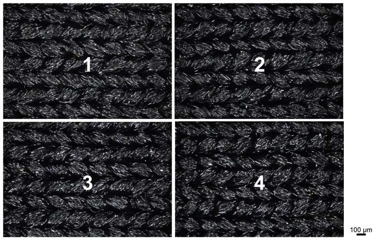
3.1. Experimental apparatus
As shown in Fig. 2(a), four fabric samples, nominally 32-mm-square swatches, were placed
on a 152.4-mm-diameter copper disk, with all samples being placed at the same radial
distance from the disk center and each sample positioned within its own 72° segment. A plate
of polished brass (emissivity of 0.03 [9]) was placed in the remaining segment to act as a
surface with approximately 100% reflectivity. To provide good thermal contact between the
copper disk and the samples, the fabric and brass were adhered to the copper disk using
thermal paste with a conductivity of 0.92 W/m K. A uniform and consistent thickness of the
thermal paste was ensured by first placing a thin template with a square cutout matching the
dimensions of the fabric sample on the copper disk, then using a blade extended across the
template to pull the paste down the application area. Upon removal of the template, a square
section of paste with a thickness matching that of the template was left behind. To ensure that
each fabric sample was placed on the thermal paste with uniform contact pressure, a 19-mm-
thick copper square with dimensions matching that of the fabric sample was briefly placed on
top of each fabric sample once it was situated on top of the thermal paste. To aid with the
automatic image analysis described below, the brass plate was framed with high emissivity
tape.
A circular resistive heating pad (Omega P/N SRMU0206D-P) with a diameter equal to
that of the copper disk was placed under the copper disk and connected to a variable voltage
supply (Payne Controls, McMaster-Carr P/N 3641K43). The cylindrical symmetry of the
apparatus helped ensure that each sample position was exposed to nominally identical thermal
conditions during the experiment. To confirm a uniform, and minimum in magnitude, radial
temperature gradient, six high-aspect-ratio holes (3.18-mm diameter by 19-mm deep) were
drilled into the 25.4-mm-thick copper disk: one in the disk center and five near the edge of the
disk in the angular centers of each of the 72° segments. These holes acted as blackbody
resonant cavities, with an effective emissivity of 1, and enabled accurate measurement of the
local temperature and maximum possible (i.e., blackbody) emissive power of the heated
copper disk. Using the measured cavity temperature of each hole, the maximum deviation in
temperature from center to edge of the disk was measured to be less than 0.2°C for a nominal
disk temperature of 35°C. The deviation in temperature between the outer holes in different
segments was measured to be less than 0.1°C, confirming uniform thermal conditions for all
sample positions.
#262126 Received 29 Mar 2016; revised 25 Apr 2016; accepted 25 Apr 2016; published 5 May 2016
(C) 2016 OSA 16 May 2016 | Vol. 24, No. 10 | DOI:10.1364/OE.24.010556 | OPTICS EXPRESS 10559Fig. 2. Experimental apparatus: a) samples mounted to copper disk, four fabric samples
containing different amounts of ceramic additive and one highly reflective brass plate are
positioned around the disk at a constant radial distance; b) the copper disk within the
measurement rig, an infrared camera is positioned above the disk, melamine foam reduces the
radial temperature gradient of the copper and a clear acrylic tube limits convection.
Figure 2(b) shows the experimental apparatus configuration used for measurements. The
copper disk was surrounded in melamine foam to reduce the radial temperature gradient, and
a clear poly(methyl methacrylate) (PMMA) cylindrical tube was mounted around the copper
disk to limit the effects of convective heat transfer in the vicinity of the samples. A scientific
grade thermal imaging camera (FLIR Systems, Inc., Model T650sc, Wilsonville, OR) was
mounted directly over the samples to acquire images at an angle normal to the surface of the
copper disk. The camera was set to detect the radiance in the MIR wavelength range between
7.5 – 14.0 µm using a 640 x 480 array of microbolometer sensors with a pitch of 25 µm, and
the vertical distance between the camera and the samples was 430 mm.
3.2. Measurement methodology and image processing
With the samples mounted, the copper disk was heated to a nominal temperature of 35°C by
adjusting the voltage controller. For these thin fabrics with a ~0.6-mm measured thickness, it
was assumed that the temperature gradient across the thickness of the fabric could be
neglected. At thermal equilibrium, the temperature of the fabric surface was taken to be equal
to that of the copper disk, and differences in radiance measured were due solely to emissivity
differences of the materials.
Once the copper disk and fabric samples reached a temperature of 35°C and stabilized for
a minimum of 1 minute, a series of 50 images were acquired by the camera at a frequency of
7.5 Hz. The images were processed to create a single composite image in which each pixel is
the mean radiance of the corresponding pixels in every image within the series. This process
was used to temporally average the images, thereby smoothing out random noise fluctuations
in the camera sensors to increase the signal-to-noise ratio.
#262126 Received 29 Mar 2016; revised 25 Apr 2016; accepted 25 Apr 2016; published 5 May 2016
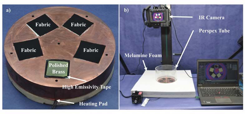
(C) 2016 OSA 16 May 2016 | Vol. 24, No. 10 | DOI:10.1364/OE.24.010556 | OPTICS EXPRESS 10560Fig. 3. Example composite radiance image and regions extracted for analysis: a) The fabric
samples, cavity holes, and the tape framing the brass plate show up as regions of high radiance.
The position of the cavity holes and the center of the copper disk, as detected by the automatic
image analysis are indicated with green crosses and a red circle, respectively; b) The regions
from which radiance data were extracted from each segment are indicated with fabric surface
regions shown in white and the brass region shown in pink.
The spatial average of the radiance over the surface of each sample was extracted from the
composite image via an image processing analysis technique. An example composite image is
shown in Fig. 3(a), the location of the cavity holes and the disk center are indicated with
green crosses and a filled red circle, respectively. Using the disk center, the copper disk was
divided into equal-sized 72° segments that each contained one sample position. Thresholding
and image masking techniques were used to extract and average the values of the pixels from
each of the fabric samples and the brass plate. To avoid capturing any emission from the
thermal paste, which can extrude slightly beyond the edge of samples, values near the edge of
the sample regions were not included in the spatial averaging. Figure 3(b) shows the image
from Fig. 3(a) with the regions from which radiance values were extracted for each of the
fabric samples and the brass plate indicated. The spatial averaging, which reduces the
measurement variation over the surface of the samples due to fabric sample properties,
allowed an average value of detected radiance to be extracted from each fabric sample and the
brass plate. In addition, the radiance values from the six cavity holes were calculated.
The emissivity of the fabric samples was calculated from the average detected radiance
values. Other laboratory measurements have confirmed that the fabrics are opaque to this
region of infrared radiation, so it is a valid assumption that no radiation from the copper disk
penetrates the fabric. The detected radiance from a given fabric sample, Wd , was taken to be
comprised of two components: radiation directly emitted by the fabric sample and ambient
radiation that is reflected from the fabric sample. The radiance due to emission from the
fabric is the product of the radiance of a black body at the sample temperature, taken as the
average radiance from the cavity holes in the copper block, and the emissivity of each sample
surface. The radiance due to the reflected ambient radiation, Wa , was calculated as the
average detected radiance from the polished brass plate with a reflectivity of ~1. Thus, the
emissivity of each fabric sample was obtained as
Wd = Wb + (1 − ) Wa
Wd − Wa (3)
= ,
Wb − Wa
where Wb is the component directly emitted by the fabric and (1 − ) Wa is the component
reflected from the fabric sample due to ambient radiation from the surrounding environment.
Note that as the sample temperature approaches the ambient room temperature, Wa
#262126 Received 29 Mar 2016; revised 25 Apr 2016; accepted 25 Apr 2016; published 5 May 2016
(C) 2016 OSA 16 May 2016 | Vol. 24, No. 10 | DOI:10.1364/OE.24.010556 | OPTICS EXPRESS 10561approaches Wd and Wb , leading to a reduction in the signal-to-noise ratio for the measured
emissivity. Thus, Eq. (3) dictates that measurements using this experimental method must be
made at sample temperatures that are above or below the ambient room temperature.
The above experiment was repeated several times with different fabric samples in each
position of the copper block. Since the magnitude of the measured changes in emissivity were
small, the cumulative measured emissivity results were monitored, using the standard
deviation for each fabric type, to estimate the reliability of the measured emissivity values as
data were accumulated. After 12 experimental runs, it was determined that further repeated
measurements were yielding little change to the average calculated emissivity of each sample
and would therefore not increase the measurement reliability. For each experimental run, the
location of the different samples was varied to ensure that any measured changes in infrared
emissive power were not due to non-ideal cylindrical symmetry of the sample thermal
environment.
4. Results and discussion
Figure 4 shows the emissivity of the fabric samples as a function of the percentage mass of
ceramic material in the fabric, xc . The data points are the mean value of the 12 independent
measurements and the error bars have a length of one standard deviation above and below the
mean. A linear fit to the data yields a trend line described by = 0.0148 xc + 0.9039 , and the
resulting line of best fit to these mean values, shown in black on the figure, has an R 2 value
of 0.976.
Fig. 4. Emissivity of the fabric samples as a function of the percentage mass of added ceramic
material. Data points are the mean of 12 independent measurements and the error bars a range
of one standard deviation above and below the data point values. The black line shows a linear
fit to the data with an R2 value of 0.976.
The emissivity of the fabric is 0.904 ± 0.003 when the fabric contains no added ceramic
particles, 0.913 ± 0.006 when the fabric contains 0.53 ± 0.03 wt% added ceramic particles,
#262126 Received 29 Mar 2016; revised 25 Apr 2016; accepted 25 Apr 2016; published 5 May 2016
(C) 2016 OSA 16 May 2016 | Vol. 24, No. 10 | DOI:10.1364/OE.24.010556 | OPTICS EXPRESS 105620.918 ± 0.004 when the fabric contains 1.03 ± 0.06 wt% added ceramic particles, and 0.923 ±
0.006 when the fabric contains 1.22 ± 0.04 wt% added ceramic particles. When ceramic
material is added to be 1.22% of the fabric mass, the emissivity is increased by 2.1% over the
case where no additional ceramic is added to the polyester/elastane blend.
The experimental methods described above were used to investigate the effects of
temperature on the fabric sample that contained 1.22% added ceramic material by mass,
achieved by mounting four samples of the 1.22% fabric on the copper disk, along with the
high reflectivity brass plate. Figure 5 shows that the resulting emissivity is independent of
temperature over the wavelength range of 7.5 – 14 µm; there is no statistically significant
correlation between the emissivity and temperature with a p-value for linear correlation of
0.216.
Fig. 5. Emissivity of the fabric containing 1.22% mass of added ceramic particles as a function
of temperature over the wavelength range of 7.5 – 14 µm.
These experiments center on the range of temperatures that may be encountered by fabrics
in garments during typical wearing activities in temperate climates. The increase in emissivity
as more ceramic is incorporated into the fabric, combined with the temperature-independent
nature of the emissivity, offer encouragement that these results may be extrapolated to a
broader range of scenarios involving more extreme temperature ranges and larger ceramic
contents.
This methodology for measuring small variations in the emissivity of fabric surfaces, and
possibly other surfaces, may find applications across a variety of fields ranging from textile
technology to research into the properties and deposition of thin-film materials. An immediate
application of this work is to use the techniques detailed above to investigate the emissive
properties of other fabrics, such as cotton or man-made fibers. This could enable, for
example, effects on the thermal performance of garments due to modifications of fabric
structure, surface texture or coating, and fiber or additive content, to be assessed. In addition,
such investigations could be used to optimize fabric structure or composition for use in
specific thermal conditions.
#262126 Received 29 Mar 2016; revised 25 Apr 2016; accepted 25 Apr 2016; published 5 May 2016
(C) 2016 OSA 16 May 2016 | Vol. 24, No. 10 | DOI:10.1364/OE.24.010556 | OPTICS EXPRESS 10563Acknowledgments Partial funding for this work was provided by Hologenix, LLC (Santa Monica, CA). We thank Ke Zhao (Exponent, Inc., Menlo Park, CA) for fruitful discussions regarding the statistical significance of the data, and Dr. Scott Seidel (Exponent, Inc., Atlanta, GA) for organizing the ash analysis of the fabric samples. #262126 Received 29 Mar 2016; revised 25 Apr 2016; accepted 25 Apr 2016; published 5 May 2016 (C) 2016 OSA 16 May 2016 | Vol. 24, No. 10 | DOI:10.1364/OE.24.010556 | OPTICS EXPRESS 10564
You can also read