INSTALLATION INSTRUCTIONS - TileWarm DIY
←
→
Page content transcription
If your browser does not render page correctly, please read the page content below

TileWarm™ DIY
         INSTALLATION INSTRUCTIONS

                                     Speedheat® US
                                     Woodstock, Georgia
                                     Phone: 678‐391‐3244
                                     Toll Free: 1‐888‐WARM FLOOR
                                     Fax: 678‐391‐3248
                                     Toll Free Fax: 1‐888‐927‐6357
                                     www.speedheat.us                1
TWDIY-000-INST-01-07-09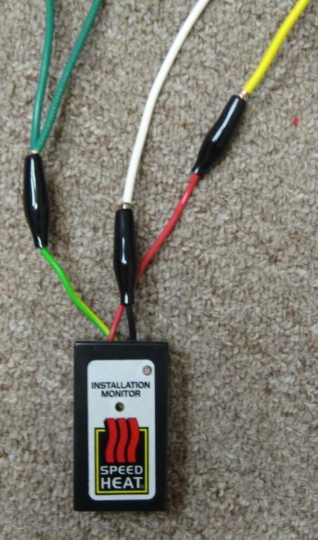
Congratulations on choosing TileWarm™ by Speedheat® as the safe, energy efficient way to add a
      touch of warmth and luxury to your floors!

      In the following pages, you will find detailed, step‐by‐step instructions for installing your new
      flexible TileWarm™ electric floor heating strips.

      For Safety Reasons and to Avoid Damaging the Product, please pay special attention to all items
      labeled:

                    Indicates a tip to help make your life
                    easier!

TWDIY-000-INST-01-07-09
TileWarm™ Installation Instructions
                                                          Index
                                                                                  Page
       IMPORTANT NOTICE                                                             1
   1.0 Electrical Rough‐in                                                          2
   2.0 Sub Floor Preparation                                                        3
   3.1 Contents of your TileWarm™ DIY System Package                                4
   3.2 Check the Contents of the Heater Package                                     5
   4.0 SecuraMat™ Measurement and Preparation                                       6
   5.0 Drywall & Sub‐floor Access Holes                                             7
   6.0 Test Heaters                                                               8–10
   7.0 Sample Heater Layout and Installation Terminology                           11
   8.0 Floor Temperature Sensor Cable Installation                                 12
   9.0   Heater Installation
                 9.1 Install Connector Block 1                                     13
                 9.2 Attach Heater Strip to the Sub Floor                          13
                 9.3 Install the Heater According to the Layout Requirements       14
                 9.4 Tear and Turn Instructions                                    15
                 9.5 Freehand Instructions                                         16
                 9.6 Install Connector Block 2                                     17
                 9.7 Fish Hookup Wires & Floor Temp. Sensor Cable thru Conduits     17
                 9.8 Cover Connector Blocks with Tape                              17
                 9.9 Re‐Attach Monitors to Heaters                                18–19
   10.0 Apply MatTac™ to Floor                                                     20
   11.0 Install SecuraMat™                                                        21–25
   12.0 Thermostat Hookup                                                          26
   13.0 Thermostat Programming                                                    27–28

   14.0 PRECAUTIONS                                                                29

   15.0 Preparation Guidelines                                                     30

TWDIY-000-INST-01-07-09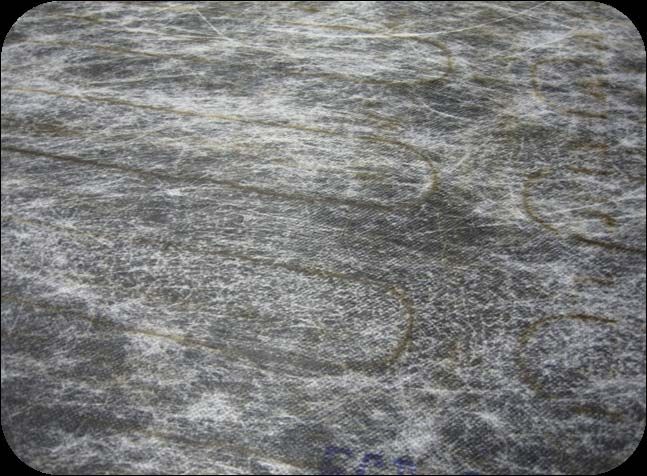
IMPORTANT NOTICE
                                           THESE INSTALLATION INSTRUCTIONS ARE ISSUED
                                            ON THE EXPRESS UNDERSTANDING THAT THE
                                           HEATING SYSTEM SUPPLIED HAS BEEN SPECIFIED
                                             BY AN AUTHORIZED SPEEDHEAT RESELLER.

                                    BEFORE PROCEEDING BE SURE OF THE FOLLOWING:
1.    You will be using vinyl or ceramic, stone, marble, or porcelain tiles for your floor covering.
      TileWarm™ heaters are not designed for installation under laminate or wood floors, wall‐to‐wall carpets, or area rugs.
      Speedheat® has other specifically designed products for those applications.
2.    The heaters supplied will adequately cover floor area to be heated without having to lengthen or shorten the element.
3.    The correct electrical requirements have been specified:
      3.1      Supply Voltage Required – 120 Volts or 240 Volts.
      3.2      Current draw (Amps).
      3.3      Required Voltage & Amperage of Dedicated Circuit Breaker.
               (Example – 240 Volt/30 Amp; 120 Volt/15 Amp ; 120 Volt/20 Amp, etc.)
      3.4      Size & Type of Electrical Boxes to house the thermostat.
               Some require ¾” knockouts for specified electrical conduit.
               (Standard size is Double Gang with Single Gang Adapter Plate).
      3.5      Electrical Cable from Service Panel to electrical box should be Correct Gauge and Number of Wires.
               (Example – 14/2; 12/2; 10/3, etc.)
      3.6      Quantity & Diameter of Electrical Conduit to be installed from the specified electrical box to floor level for hookup wires
               and floor temperature sensor cable.
               (Example – ½”; ¾”; plastic or metal). Thermostat box must have correct knockouts for conduit size.

                  CAREFULLY READ THE PRECAUTIONS AND PREPARATIONS ON PAGES 29 TO 30
     TWDIY-000-INST-01-07-09                                                                                                      Page 1 of 30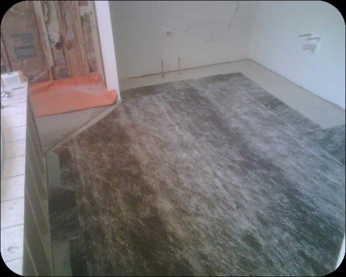
1.0 Electrical Rough-in

       Cable from                          Double Gang Electrical Box
       Dedicated                           with at least two (2) ¾” knockouts
     Circuit Breaker                       with Single Gang Adapter Plate for
    in Service Panel                       the Thermostat

                                            Wall Stud

                                           One (1) or Two (2) ¾” Electrical
                                           Conduits for Floor Temperature
                                           Sensor Cable & Heater Hookup
                                           Wires
                                           (as specified with TileWarm™ DIY system).

                                                                       Complete Electrical Rough‐in BEFORE Heater
                  Heater Hookup Wires                                  Installation
                                           Drywall
                                                                       1.1. Check that voltage and amperage of
                                                                             circuit breaker is as specified in TileWarm™
                                        Floor Temperature                    DIY electrical requirements.
                                           Sensor Cable                1.2. Ensure the cable from the service panel
                                                                             is the correct gauge to carry the load specified
                       Plate                                                 in the TileWarm™ electrical requirements.
                                                                       1.3. Ensure the single gang adapter plate (mud ring)
                                                                             has the correct lip size and has been correctly
                                                                             attached for a flush mount thermostat.
                                                                       1.4. ENSURE THAT ELECTRICAL BOXES AND
                                                                             CONDUITS COMPLY WITH LOCAL ELECTRICAL
                                                                             REGULATIONS.
Heating Element

 TWDIY-000-INST-01-07-09                                                                                           Page 2 of 30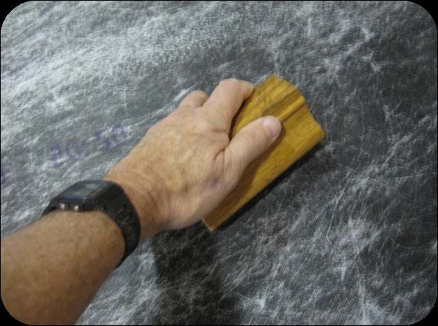
2.0 Sub Floor Preparation

   2.1                                                           2.2

2.1 PLY WOOD SUB FLOOR PREPARATION                            2.2 CONCRETE SLAB REPARATION
2.1.1. Cover the ply wood sub floor with a cement board       2.2.1. Concrete slab must be dry and cured. Any surface cracks
de‐coupler in accordance with the tile manufacturer’s         to be filled in accordance with tile manufacturer’s
requirements.                                                 requirements.
2.1.2. Fill or cover gaps between adjoining cement boards.    2.2.2. Ensure the floor is smooth and free from protruding
2.1.3. Ensure the floor is smooth and free from protruding    lumps of cement, etc.
screws, nails, lumps of cement, etc.                          2.2.3. Thoroughly sweep or vacuum all dust off prepared sub
2.1.4. Thoroughly sweep or vacuum all dust off prepared sub   floor. Use a damp cloth to remove dust from new concrete
floor.                                                        slabs.

TWDIY-000-INST-01-07-09                                                                                            Page 3 of 30
3.1    TileWarm™ DIY System Package Contents

        120 Volt
         Heater                           MatTac™ Primer
                                         with Roller and Tray

                                                                                     Wooden Block
                                                                                     for Smoothing
                                                                                                            DetectaBreak™
                                                                                      SecuraMat™
                                                                                                              Continuity
                                                                                                               Monitor

                     SecuraMat™                                                                      SmartStat™ Box
                     Protective                                                                      (Thermostat, Floor
                     Membrane                                                                          Temp. Sensor
                                                                                                       Cable, Screws)

                                  Connector
                                   Block 1

                                                 Hookup Wire             Connector
                                                Neutral + Ground          Block 2
TWDIY-000-INST-01-07-09                                                                                               Page 4 of 30
3.2 Check the Contents of your Package

      3.2.1 Before opening, check the labels on the outer plastic bag to          Notes:
            ensure the heating system received corresponds with that              _____________________
            which was ordered.
      3.2.2 CAREFULLY cut off one end of the outer plastic bag using a
                                                                                  _____________________
            pair of scissors. Remove the heating element from the                 _____________________
            inner plastic bag.
                                                                                  _____________________
      3.2.3 Note the voltage, model number, serial number, and factory
            rated resistance shown on the identity label.
                                                                                  _____________________
              DO NOT remove the label.                                            _____________________
      3.2.4 Clearly identify whether the unit is 120V or 240V.                    _____________________
            This is shown on the identity label, but as an additional             _____________________
            check, hookup wires are color coded:
                                                                                  _____________________
              3.3.4.1. 120V units have ONE (1) YELLOW wire, ONE (1)
                        WHITE wire, and TWO (2) GREEN ground wires                _____________________
                        attached to the element via a plastic block.              _____________________
              3.3.4.2. 240V units have ONE (1) RED wire, and ONE (1)              _____________________
                        BLACK wire, and TWO (2) GREEN ground wires
                        attached to the element via a plastic block.              _____________________
                                                                                  _____________________
      Note:                                                                       _____________________
      Hookup Wires may have been Inserted inside Cardboard Core                   _____________________
      During Packaging.
                                                                                  ______

TWDIY-000-INST-01-07-09                                                                                      Page 5 of 30
4.0 Measure out SecuraMat™ Protective Membrane

                                                                              4.1. SecuraMat is supplied in a roll sufficient to cover
                                                                                   the heated area plus 2" extra all the way round.

      SAMPLE SecuraMat™ LAYOUT                                                4.2   Measure out the SecuraMat BEFORE installing the
                                                                                    heating element.
                                                                              4.3   Make Sure Measurements are accurate!
                                                      This piece cut from           You CANNOT CUT SecuraMat after
                                                     SecuraMat Section 1            IT HAS BEEN GLUED OVER THE
                                                       must be used for             HEATING ELEMENT
                                                     Sections 4, 7, and 8
                                                                              4.4   DO NOT REMOVE THE WAX PAPER FROM THE
                                                                                    SecuraMat DURING THE MEASURING PROCESS.
                                                                                    (It will stick to itself and everything around it if you do.)

                                                                              4.5   Measure out Section 1 of the SecuraMat to cover
                                                             8                      an additional 2” around heating element.
                                                                  7                 Starting at a logical position on the floor.
                                                                      4
Starting point                           1                                    4.5   Measure out Section 1 of the SecuraMat to cover
                                     3’ x 10’                                       an additional 2” around heating element.
                                                                                    Starting at a logical position on the floor.
                                                                                    (that’s right… measure twice before 4.6)
                                                                              4.6   Did you measure twice? You can only cut once, you
                                             2
                                                                                    know?
                                          3’2
                                            x 10’                                   Now, cut with a knife or scissors to fit the floor
                                                                                    layout.
                                                                              4.7   Save pieces cut out of each section to cover small
                3                                     6           7                 additional areas.
            3’ x 2’ 3”   4           5
                                 3’ x 2’ 6”                                   4.8   Measure out Section 2 and cut to fit the floor
                                                                                    layout. AND SO ON.
                                                                              4.9   Roll up each section and remove from the room
                                                                                    until required for installation over the heating
                             8                                                      element.
                                                3’ x 1’ 2”

                                                                                                                                      Page 6 of 30
5.0 Dry Wall & Sub Floor Access Holes

                                                               Drywall

      3” x 4” Hole in Drywall
       to Expose Electrical                             Electrical Conduits from
             Conduits                                   Thermostat Box.

                                                        Install Number of ¾”
     Plate (Horizontal stud)                            Conduit Specified with
            in Drywall                                  TileWarm™ DIY System.

        4” x 4” x ¼” Hole in
          Cement Board
         or Concrete Slab                                  Cement Board on
       for Connector Blocks                              Plywood Sub floor or
                                                            Concrete Slab

              16” x ½” x ¼”
                Channel in
              Cement board
             or Concrete Slab
                 for Floor
              Temperature
               Sensor Cable

TWDIY-000-INST-01-07-09                                               Page 7 of 30
6 Test Heater
6.1.1 Each Heater is shipped, rolled around a cardboard
core and packed in a double plastic bag
6.1.2 Remove the heater from plastic bags for testing.
6.1.1
Each Heater has 2 pairs of heater hook up wires.
The “inner” pair of heater hook up wires is inserted in the
cardboard core to avoid twisting and damage to the
element when the heater is unrolled from the core during
installation.
6.1.3 Carefully remove the “inner” pair of heater hook up
6.1.2
wires from the core to expose the stripped ends of
the wires so the heater can be tested with the
DetectaBreak™ Continuity Monitor before
continuing installation.
6.1.3
The “outer” pair
of heater hook up
wires is secured
to the outside of
the heater roll.
“Outer” pair of heater hook up wires.
“Inner” pair of heater hook up wires.
TWDIY-000-INST-01-07-09 Page 8 of 306.2 DetectaBreak Continuity Monitors
6.2 Monitor As Received In Package
6.2.1 One DetectaBreak™ Continuity Monitor is shipped with
each heater. It is firstly used to test that the heater is good
before installation and is later reconnected to continuously
monitor the electrical integrity of the heater during tile
setting.
6.2.2 The monitor is shipped with the alligator clips of the RED
and BLACK monitor leads connected together. This keeps
6.2.1
the unit silent and puts it into “sleep mode” to extend
battery life.
6.2.2 Red and Black leads 6.2.3 When the RED and BLACK Monitor leads are separated, the
connected to each unit will chirp 3 times then emit a continuous alternating
other to keep tone until connected to a good heater as described in 6.3
monitor silent in or 6.4.
sleep mode.
6.2.4 TO SILENCE THE MONITOR AT ANY TIME, RECONNECT THE
RED AND BLACK MONITOR LEADS
6.2.2
TWDIY-000-INST-01-07-09 Page 9 of 306.3 Test 120‐Volt TileWarm™ DIY Heater
6.3.1 Twist together the stripped ends of the two (2) GREEN
heater hook up wires.
6.3.2 Attach GREEN/YELLOW monitor lead to both GREEN
heater hook up wires.
6.3.3 Attach RED monitor lead to YELLOW heater hook up wire.
6.3.4 Attach BLACK monitor lead to WHITE heater hook up wire.
…Continue to 6.4.5…
6.4 Test 240‐Volt TileWarm™ DIY Heater
6.4.1 Twist together the stripped ends of the two (2) GREEN
heater hook up wires.
6.4.2 Attach GREEN/YELLOW monitor lead to both GREEN 6.4
6.3 heater hook up wires.
120‐Volt Heater 6.4.3 Attach RED monitor lead to RED heater hook up wire. 240‐Volt Heater
6.4.4 Attach BLACK monitor lead to BLACK heater hook up wire.
IF HEATER IS WORKING PROPERLY
6.4.5 If heater is good, monitor will go silent and a GREEN LED
will flash continuously on the face of the monitor.
6.4.6 Disconnect Monitor from heater and reconnect RED and
BLACK monitor leads to each other to silence the unit.
IF DAMAGED
6.5 VERY IMPORTANT 6.4.7 If heater has been damaged, monitor will continue to emit
Carefully re‐insert an alternating tone and a RED LED will flash continuously.
6.5
“inner” pair of heater 6.4.8 Disconnect Monitor from heater and reconnect RED and
hook up wires into BLACK monitor leads to each other to silence the unit.
cardboard core before IF DAMAGED, DO NOT CONTINUE INSTALLATION!
continuing with Call 1‐888‐WARM‐FLOOR
installation.
(1‐888‐927‐6356 Ext. 201) for further instructions.
TWDIY-000-INST-01-07-09 Page 10 of 307.0 Sample Heater Layout & Installation Terminology
“Tear & Turn” – See 9.4
2d Freehand – See 9.5
Floor
temperature
sensor cable –
See 8.0
1b 1c 1d
2a 2b 2c
1a
Heater 1 Heater 1 Heater 2 Heater 2 Heater
“out” “in” “out” “in” “in”
hot tail hot tail hot tail hot tail hot tail
Heater Floor temperature
“out” sensor cable
hot tail
TWDIY-000-INST-01-07-09 Page 11 of 308.0 Floor Temperature Sensor Installation
Drywall
Drywall
Floor temperature
sensor cable
Duct Tape
Cement Board
Cement Board Thicker Tip of the on Plywood
on Plywood Floor Temperature Sub Floor or
Sub floor or Sensor Cable Concrete Slab
Concrete Slab
8.1 Place Floor Temp. Sensor Cable in the channel cut out 8.3 Cover the floor temperature cable with
in the sub floor. duct tape.
8.2 The tip of the cable (which is thicker than the rest of
the cable) should be positioned so that it will be
covered by the heating element.
TWDIY-000-INST-01-07-09 Page 12 of 30Drywall
9.1
Out Hot tail 9.0 Heater Installation
Heater Hookup 9.1 Install Connector Block 1
Wire
9.1.1 Secure Connector Block 1 for the
“Out Hot Tail” to the ply wood sub
Insulated Staple
floor with an insulated staple.
9.1.2 On a concrete slab, use hot glue to
Connector Block 1 stick the block to the sub floor.
NEVER ALLOW
Cement Board on
Plywood Sub‐floor
ELEMENT WIRES TO
Floor Temperature CROSS OVER EACH
Sensor Cable or Concrete Slab
OTHER!
9.2 Attach Heater Strip to the Sub‐floor 9.2
9.2.1 Secure the “Out Hot Tail” to the sub floor with masking or duct
tape. Adhesive Tape 2 Masking
Out Hot tail Tape
9.2.2 Remove factory fitted wax paper from Adhesive Tape 1 about
24” at a time.
9.2.3 Attach the first 24” of Adhesive Tape 1 to the floor. Press
firmly into place.
9.2.4 Remove the next 24” of Adhesive Tape 1. Press firmly to the
floor in a straight line with the previous 24”
9.2.5 Remove factory fitted wax paper from Adhesive Tape 2, about
12” at a time.
9.2.6 Stretch out the heater strip so that the element wire is straight.
Adhesive Tape 1
9.2.7 Attach first 12” of Adhesive Tape 2 to the floor. Press firmly
into place.
9.2.8 Remove the next 12” of Adhesive Tape 2. Stretch & stick. Wax Paper on
Adhesive Tape Page 13 of 30
TWDIY-000-INST-01-07-099.0 Heater Installation
Sample Heater Layout
9.3 Install Heater According to
Layout Requirements
9.3.1 Continue installing the
heater according to the pre‐
“Tear & Turn” – See 9.4 determined layout requirements.
9.3.2 See 9.4 for “Tear and Turn”
instructions.
2d Freehand 9.3.3 See 9.5 for “Freehand” instructions.
(See 9.5)
Floor
temperature
sensor cable –
See 8.0 NEVER ALLOW
1b 1c 1d ELEMENT WIRES TO
2a 2b 2c
CROSS OVER EACH
OTHER!
1a
Heater 1 Heater 1 Heater 2 Heater 2
“out” “in” “out” “in”
hot tail hot tail hot tail hot tail
TWDIY-000-INST-01-07-09 Page 14 of 309.4.1 Connector Block 1 9.0 Heater Installation
9.4 Tear & Turn Instructions
9.4.1 Identify Correct
turn Loop A
Use this method to turn the heater through 180°
9.4.1 Identify the correct turn Loop A according to the layout
Tape 1 requirements.
9.4.2 Carefully cut or tear Tape 1.
DO NOT CUT THE HEATING ELEMENT.
9.4.3 Carefully cut or tear Tape 2.
Tape 2 Connector block 2 DO NOT CUT THE HEATING ELEMENT.
9.4.4 Turn Section 2 of the heater through 180°.
9.4.2 9.4.5 Attach heater sections 1 and 2 to the floor with the factory
fitted adhesive tape.
Section 1
9.4.4
Loop A
Section 2
Section 2 9.4.2 Carefully Cut Section 1 Turned
or Tear Tape 1 through
180°
9.4.3 Loop A
NEVER ALLOW 9.4.4 Turn Heater
9.4.3 Carefully Cut or ELEMENT WIRES TO Section 2
Tear Tape 2 CROSS OVER EACH through
OTHER! 180°
TWDIY-000-INST-01-07-09 Page 15 of 30A to B = Element Run 9.0 Heater Installation
A B
9.5 FREEHAND INSTRUCTIONS
C C to D =
D Element Pitch
Covering Odd‐shaped Sections of the Floor
9.5.1 Detach the heating element from the factory fitted
adhesive tape by giving it a sharp tug upwards.
YES √ 9.5.2 Keep the 2 pieces of adhesive tape from which the
element has been removed and use it to attach the
freehand sections of element to the sub floor. Use
masking tape or duct tape to adhere the element to the
sub‐floor if more tape is required.
9.5.3 Alternatively, tear the tape between each element run,
leaving small pieces of tape attached to the element to
stick to the sub‐floor.
9.5.4 Maintain the same “element pitch” between “element
runs” as the original strip. This spacing varies from 1.24”
to 2.5” depending on the power density of the heater.
NO X Never Allow Element
Wires to Cross Over
Each Other!
TWDIY-000-INST-01-07-09 Page 16 of 309.0 Heater Installation
9.6
9.6 Install Connector Block 2
Connector
9.6.1 Secure Connector Block 2 for the “In Hot Tail” to the
Block 2
plywood sub floor with an insulated staple.
9.6.2 On a concrete slab, use hot glue to stick the block to
the sub floor. Insulated
Staple
In Hot Tail
9.7
9.8
9.7 Fish Wires & Sensor Cable into Conduit
9.7.1 Fish the heater hook up wires and floor temperature sensor cable
through the electrical conduits in the dry‐wall up to the electrical
box which will house the thermostat.
9.8 Cover Connector Blocks with Tape
9.7.2 Tape the hook up wires together for each heater with electrical
tape just above the point at which the wires enter the electrical box 9.8.1 Cover the element blocks in the 4” x 4” x 1/4”
from the electrical conduit. cut out in the sub floor and with duct tape.
9.7.3 Separately identify the 4 wires for each heater to simplify the re‐
attachment of the Continuity Monitor later.
TWDIY-000-INST-01-07-09 Page 17 of 309.0 Heater Installation
9.9
9.9 Re‐attach Monitors to Heaters
9.9.1 Re‐Connect a DetectaBreak™ Continuity
Monitor to each heater according to the
instructions that follow.
(See Section 9.9.4)
9.9.2 Tape around the alligator clips with
electrical tape so that false alarms do not
occur if the Monitor is accidentally
bumped and the alligator clips touch each
other.
9.9.3 Ensure that the floor temperature sensor
cable has been fished through the
conduit and that it is secured so it will
not fall back down the conduit..
TWDIY-000-INST-01-07-09 Page 18 of 309.9 Attach Monitors to Heaters 9.0 Heater Installation
9.9.4 Re‐attach DetectaBreak™ Monitor to 120‐Volt
TileWarm™ DIY Heater
9.9.4.1 Attach RED monitor lead to YELLOW heater hook up wire
and BLACK monitor lead to WHITE heater hook up wire.
9.9.4.2 Attach GREEN/YELLOW monitor lead to both GREEN
heater hook up wires tightly twisted together.
…Continue to 9.9.6.1…
9.9.4 9.9.5 Re‐attach DetectaBreak™ Monitor to 240‐Volt
TileWarm™ DIY Heater 9.9.5
9.9.5.1 Attach RED monitor lead to RED heater hook up wire and
BLACK monitor lead to BLACK heater hook up wire.
9.9.5.2 Attach GREEN/YELLOW monitor lead to both GREEN
heater hook up wires tightly twisted together.
…Continue to 9.9.6.1…
IF HEATER IS WORKING PROPERLY
9.9.6.1 If heater is good, monitor will go silent and a GREEN LED will flash continuously on the face of the monitor.
9.9.6.2 Disconnect Monitor from heater and reconnect RED and BLACK monitor leads to each other to silence the unit.
IF DAMAGED
9.9.6.3 If heater has been damaged, monitor will continue to emit an alternating tone and a RED LED will flash continuously.
9.9.6.4 Disconnect Monitor from heater and reconnect RED and BLACK monitor leads to each other to silence the unit.
IF DAMAGED, DO NOT CONTINUE INSTALLATION!
Call 1‐888‐WARM‐FLOOR
(1‐888‐927‐6356 Ext. 201) for further instructions.
TWDIY-000-INST-01-07-09 Page 19 of 3010.0 Apply MatTac Primer
Before applying the MatTac™
primer, ensure that the floor is still
clean and free of dust.
10.1 Apply MatTac™ Primer to the floor.
10.1.1 Pour MatTac™ Primer from the bottle into the plastic tray supplied.
10.1.2 Dip the supplied Roller into MatTac™ Primer until the roller is fully
covered.
10.1.3 Apply a thin film of MatTac™ Primer evenly across the floor with the
roller.
10.1.4 Do not apply excessive primer as it can slow drying time.
10.1.5 Some floor surfaces may be more absorbent than others and may
10.1 require an extra coat of MatTac™ Primer. c
10.2 Allow MatTac™ Primer to dry.
10.2.1 Drying takes 10 to 45 minutes dependant on temperature and
humidity.
10.2.2 The MatTac™ Primer is sufficiently dry when it is “tacky” to the
touch and no liquid is transferred to your fingers.
10.2.3 Protect primed surface from dust and dirt until SecuraMat™ is
installed. You can walk on the primer to install the SecuraMat™.
10.2.3 SecuraMat™ protective membrane must be installed within 4 hours
of the MatTac™ Primer drying.
10.3 Clean up
10.3.1 The roller and tray are disposable, but may be cleaned with plain
10.2 water and a cloth before the primer dries.
10.3.2 If the primer has already dried on the equipment, use mineral
spirits to clean up.
TWDIY-000-INST-01-07-09 Page 20 of 3011.0 Install SecuraMat
11.1 Important Precautions
11.1.1 THE BLACK UNDERSIDE OF THE SecuraMat™ IS COVERED WITH
A VERY AGGRESSIVE ADHESIVE.
11.1.2 DO NOT FOLD MAT on Underside. If the mat is folded over on the underside, it will stick to itself
and CANNOT BE SEPARATED.
11.1.3 REMOVE 1 ft or less of the White Wax Paper at a time to avoid this.
11.1.4 Hold the roll upright and taught at a 90° angle to the floor while rolling out onto the primed floor.
White Wax Paper Protective Layer
Black Underside Covered with Aggressive Adhesive
TWDIY-000-INST-01-07-09 Page 21 of 3011.0 Install SecuraMat
11.2 Install SecuraMat onto the Primed Floor
11.2.1 Roll back 1 ft. of 11.2.3 Lift the previously
White wax paper measured section
on the first of SecuraMat
section of upright and taught
previously at a 90o angle to
measured the floor.
SecuraMat to
expose the black
11.2.1 adhesive
underside. 11.2.3
11.2.2 Flip the section of 11.2.4 Stand on the first
11.2.2
SecuraMat over 1ft. portion of
into the correct SecuraMat already
starting position secured to the
on the primed floor.
floor and press
the exposed black
adhesive
underside firmly
into place.
11.2.4
TWDIY-000-INST-01-07-09 Page 22 of 3011.0 Install SecuraMat
11.2 Install SecuraMat onto the Primed Floor
11.2.5. Still standing on the first portion already secured to the
floor, remove another 1 ft. of white wax paper and lower
the exposed black adhesive underside of the mat down
onto the primed floor.
11.2.6. Walk forward 1 ft. and unroll another 1 ft. of white wax
paper. The weight of the mat and the pressure from your
feet will lightly adhere the mat to the floor.
11.2.7. Keep walking forward and unrolling until you reach the end
of the measured out section of SecuraMat.
11.2.8. Repeat for each section of previously measured SecuraMat.
11.2.9 As far as possible, each section of SecuraMat should be
butted up against the edge of an adjoining section and
should not overlap.
TWDIY-000-INST-01-07-09 Page 23 of 3011.0 Install SecuraMat
11.2 Install SecuraMat onto the Primed Floor
11.2.10. Using the wooden block supplied, apply moderate 11.2.11. When the profile of the heating element shows
pressure to the top surface of the SecuraMat to through the surface of the SecuraMat across the
remove any air that may have been trapped entire heated area, you can be sure all the
during the roll out process. trapped air has been removed.
TWDIY-000-INST-01-07-09 Page 24 of 3011.0 Install SecuraMat
11.3 Completed Sample Installation
Continuity Monitors
SecuraMat section 1 with cut out to fit floor layout. Adjoining SecuraMat sections butted against each other, not
overlapped
TWDIY-000-INST-01-07-09 Page 25 of 3012.1 Thermostat auto senses 120 Volt or 240 Volt system
12.2 Strip ¼” of insulation from red and green wires in 12.0 Thermostat Hookup
floor temperature sensor cable.
12.3 Press down on 2 spring loaded screws of the Floor Sensor
Block, insert red and green wires, then release screws.
12.4 Tug on sensor cable to insure firm connection. Floor Sensor Block with
12.5 If sensor cable is incorrectly installed, E2 error will spring loaded screws. Heater Grounds
be shown on thermostat display when connected to power. Green
12.6 Insert heater hot and neutral hookup wires into screw
connectors as shown. House
12.7 Connect house ground to heater grounds with a screw Ground
Floor Temp.
connector. USE THE CORRECT SIZE CONNECTOR. Sensor Cable
Copper
12.8 Insert the hot and neutral wires from the circuit breaker
in the service panel, into the screw connectors as shown.
12.9 Some installations with more than 3 heaters on one thermostat
may require a separate relay/contactor and would be
connected within a junction box. Hot
Heater
Heater Neutral
Floor Sensor Block with Hot Cable from
Heater Grounds Neutral
spring loaded screws. Yellow Circuit Breaker
Green White
14/2 or 12/2
House 120 VOLT SYSTEM
Ground
Copper
Floor Temp.
Sensor Cable
CONNECT MULTIPLE HEATERS IN PARALLEL.
USE PIGTAIL WIRES IF NECESSARY.
USE CORRECT SIZE SCREW CONNECTORS
Heater Heater Hot 2 Hot 1 FOR THE NUMBER OF WIRES TO BE CONNECTED.
Hot 2 Hot 1 Cable from
Black Red Circuit Breaker
12/2 or 10/2
240 VOLT SYSTEM TWDIY-000-INST-01-07-09 Page 26 of 3013.1 First Time Power On 13.0 Thermostat Programming
13.1.1 Set correct time and correct day using Up and Down Adjust
Buttons. At first time power on, Clock flashes 12:00 midnight
13.1 First Time Power on
Day flashes 1 = Monday.
13.1.2 To adjust Clock and Day later on, insert pin into Clock Adjust Hole,
then use Up and Down Adjust Buttons.
13.1.3 The thermostat has a 4 ‐ event time and AIR temperature program
for Days 1 thru 5 and a 2‐event program for days 6 and 7.
SPEEDHEAT
13.1.4 The Adaptive function of the thermostat calculates when to switch
ON the heating to ensure that the set temperature is achieved at Display
the set time.
Up Adjust
13.1.4 To program the thermostat, hold down the Accept Button for 3 Button
seconds until a time appears on the display (e.g.. 6:00). Release
the button and the Event 1 start time will flash ready for Accept
adjustment. Button
13.1.5 Use Up and Down Adjust Buttons to set Event 1 start time. Press
the Accept Button to accept this time. Down
Adjust
13.1.6 A temperature will now flash on the display. Use Up and Down Button
Adjust Buttons to set Event 1 temperature. Press the Accept
Button to accept this temperature.
Clock Reset to
Adjust Factory
13.1.7 Event 2 time will now flash on the display. Use Up and Down
Hole Default
Adjust Buttons to set Event 2 start time. Press the Accept Button
Hole
to accept this time. And so on for 4 weekday events and 2
weekend events.
13.1.8 Typically :
Event 1 = Morning wake up time.
Event 2 = Leave home time.
Event 3 = Return home time
Event 4 = Evening sleep time.
Page 27 of 30
TWDIY-000-INST-01-07-0913.0 Thermostat Programming
13.2 Maximum and Minimum FLOOR Temperatures.
13.2.1 For wood floors, the MAXIMUM FLOOR temperature 13.2 Maximum and Minimum Floor
should not exceed 83oF. Temperatures
13.2.2 Because hot air rises, it is often important to ensure that
the MINIMUM FLOOR temperature does not fall below
a comfortable level when the AIR temperature set point
has been achieved. SPEEDHEAT
13.2.3 Hold down the Up Adjust Button and Down Adjust
Button together for 3 seconds until “Info” flashes on
Display
the display.
13.2.4 Press Up Adjust Button once and “Pro” will appear on Up Adjust
the display. Press the Up Adjust Button once again and Button
“HiLi” will flash on the display.
Accept
13.2.5 Press the Accept Button and a temperature will flash on Button
the display. Use Up and Down Adjust Buttons to set
MAXIMUM FLOOR temperature to 83oF.
Down
Adjust
13.2.6 Press the Accept Button and “LoLi” will flash on the Button
display. Press the Accept Button and a temperature will
flash on the display. Use Up and Down Adjust Buttons
to set MINIMUM FLOOR temperature to (say) 75oF. Clock Reset to
Adjust Factory
13.2.7 Press the Accept Button and the current time will return Hole Default
to the Display. Hole
There are several other functions described in the full
THERMOSTAT USER MANUAL which is packed in the
box in which the thermostat is shipped.
TWDIY-000-INST-01-07-09 Page 28 of 3014.0 Precautions
14.1 REGULATIONS
14.1.1 THIS EQUIPMENT IS AN ELECTRICAL FIXTURE AND SHALL ONLY BE INSTALLED BY QUALIFIED PERSONNEL WHO ARE
FAMILIAR WITH THE CONSTRUCTION AND OPERATION OF THE APPARATUS AND THE HAZARDS INVOLVED.
14.1.2 INSTALLATION OF THIS HEATING SYSTEM SHALL BE IN ACCORDANCE WITH THE REGULATIONS OF ALL AUTHORITIES
HAVING JURISDICTION.
14.1.3 THE ELECTRICAL HOOK UP WIRES FOR THIS HEATING SYSTEM MUST BE ENCLOSED IN ELECTRICAL CONDUIT WHEN
DRAWN UP THROUGH DRY WALL.
14.2 DAMAGE AND REPAIRS
14.2.1 DO NOT Install the Heating System if the Continuity Test Fails.
14.2.2 DO NOT Cut, Shorten or Lengthen the Heating Element.
14.2.3 DO NOT Attempt to Repair the Heating Element, Connection Block or Hookup Wires if they are Damaged During or after
Installation.
14.2.4 DO NOT Remove Excess Thinset from a Trowel by Banging it on the Heating Element, the Connection Block or the Cold
Wire Leads.
14.2.5 DO NOT Use Excessive Pressure with the Notched Trowel when Applying Thinset over the Protective Mesh and the
Heating Element.
14.2.6 DO NOT Use an Angle Grinder to Cut Tiles Installed over the Heating Element.
14.2.7 DO NOT Clean Out Thinset or Grout Between Adjoining Tiles Using a Sharp Object which Extends below the Bottom
Surface of the Tile.
14.3. POSITIONING
14.3.1 DO NOT Install One Heating Strip on Top of Another or Overlap the Strip on Itself as it may Cause Dangerous
Overheating.
14.3.2 DO NOT Install Heating Element Under Cabinets or Other Built‐in Units.
14.3.3 DO NOT Install Heating Element Closer than 8 Inches to Heating Supply Ducts, other Heating Elements or other Heating
Appliances or Sources of Heat.
14.3.4 DO NOT Install the Heating Element over Floor Expansion Joints.
14.3.5 DO NOT Install the Heating Element over Rough And Uneven Floors.
14.3.6 DO NOT Install the Heating Element over Protruding Screws, Nails, Staples.
14.3.7 DO NOT Install the Heating Strip UNDER Insulating or Water‐proof Underlayment.
TWDIY-000-INST-01-07-09 Page 29 of 3015.0 Preparation Guidelines
15.1. WALL AND FLOOR POSITIONING CONSIDERATIONS
15.1.1 BEFORE planning the floor layout for heating elements, an appropriate wall position must be selected for the thermostat.
The Following Requirements SHOULD be Considered:
15.1.1.1 Electrical cable must be installed from the service panel to the selected wall position.
15.1.1.2 The SmartStat™ will be installed in an electrical box , which will be secured to a vertical stud in the dry wall no more
than 5 feet above floor level. A single gang electrical box is large enough to receive hookup wires from a maximum
of two heaters. A double gang electrical box with a single gang reduction plate (mud ring), may be used for up to 3
heaters attached to a single thermostat.
15.1.1.3 Electrical conduit will be installed from the electrical box for the thermostat to the horizontal stud at floor level.
15.1.1.4 The heater hookup leads will be drawn up through electrical conduit in the dry wall from a point at floor level no
more than 5 feet below the thermostat.
15.1.1.5 The thermostat should be in a convenient position for safe and easy access by occupants of the room; preferably on
an internal wall away from direct sunlight and drafts.
15.1.2 The Following Flooring Criteria MUST be Considered:
15.1.2.1 The heating element cannot be installed directly onto a plywood sub‐floor. Cement board or a de‐coupler must be
installed first.
15.1.2.2 Elements CAN be installed directly onto concrete floors.
END
Speedheat® TileWarm™ Installation Instructions
TWDIY-000-INST-01-07-09 Page 30 of 30Thank you for choosing Speedheat! Enjoy your New Warm Floors!
Speedheat® Generation4™
Energy Efficient Electric Radiant Floor Heating Systems

   Speedheat® is the world leader in Generation4™
   electric radiant floor heating systems.

   Primary, Supplementary, and Floor Warming
   Systems available:
   CarpetMate™
          Wall-to-Wall Carpeting
   RugBuddy™
          Area Rug Heaters, Foot Warmer
   TileWarm™, VinylPal™, and ShowerWarm™
          Tile, Marble, Slate, and Stone, Vinyl & Linoleum, Showers
   WoodBeWarmer™
          Nailed Down Wood
   LamiMate™
          Floating Laminate

                                                                      Speedheat® US
                                                                      Woodstock, Georgia
                                                                      Phone: 678‐391‐3244
                                                                      Toll Free: 1‐888‐WARM FLOOR
                                                                      www.speedheat.us

TWDIY-000-INST-01-07-09
You can also read