CODESYS IEC 61850 Server - Programming System SOFTWARE MANUAL
←
→
Page content transcription
If your browser does not render page correctly, please read the page content below
SOFTWARE MANUAL

CODESYS IEC 61850 Server
Programming System
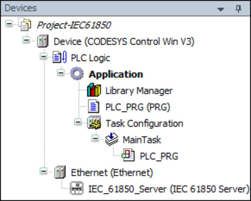
Table of contents

—
Table of contents
1     IEC 61850 Server............................................................................................................................................. 3
      1.1 IEC 61850 Server...................................................................................................................................... 3
      1.2 Quickstart.................................................................................................................................................. 3
      1.3 Editor of the IEC 61850 Server................................................................................................................ 11
           1.3.1     IEC 61850 Editor...................................................................................................................... 11
           1.3.2     Configuration............................................................................................................................ 11
           1.3.3     DataSet.................................................................................................................................... 21
           1.3.4     Report...................................................................................................................................... 22
           1.3.5     GOOSE Publisher.................................................................................................................... 24
           1.3.6     GOOSE Subscriber.................................................................................................................. 26
           1.3.7     Information............................................................................................................................... 28
      1.4 Reading and Writing from CODESYS Variables .................................................................................... 28
      1.5 Menu Command sorted by Categories.................................................................................................... 29
           1.5.1     IEC61850................................................................................................................................. 29
      1.6 Logical Name Classes (LNC).................................................................................................................. 30
      1.7 IEC 61850 Functionalities....................................................................................................................... 31
2     Index............................................................................................................................................................... 36

2                                                                     3ADR010671, 4, en_US                                                                     2021/02/02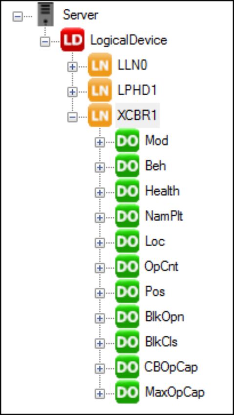
IEC 61850 Server
                                                                                                      IEC 61850 Server

—
1 IEC 61850 Server
1.1 IEC 61850 Server
                  The package CODESYS IEC 61850 Server is a configurator for creating an IEC 61850 Server
                  according to IEC 61850. The IEC 61850 is the communication standard for switchgear
                  automation of medium and high voltage technology.
                  The essential features of this package are::
                  ●    Configuration of data models for IEDs (Intelligent Electronic Device) with logical devices,
                       logical nodes, data objects and data attributes
                  ●    Generation of the corresponding IEC 61131-3 code
                  ●    Mapping of data attributes to IEC 61131-3 variables
                  ●    Configuration of dynamic datasets
                  ●    Buffered and unbuffered Reports
                  ●    Protocols implemented: MMS and GOOSE
                  ●    Import /Export of different SCL formats

Inserting the     The IEC 61850 Server is inserted below an Ethernet Adapter in the device tree. For this select
IEC 61850         the Ethernet Adapter in the device tree and activate the context menu command “Add device...”.
Server into the   In the opened dialog select the IEC 61850 Server in the “Miscellaneous ” category and activate
device tree       the “Add device ” button .
                  The configuration of the IEC 61850 Server takes place in the Ä Chapter 1.3.1 “IEC 61850
                  Editor” on page 11.

1.2 Quickstart
                  Here, a project with an IEC 61850 Server is created as an example. After the configuration of
                  the Server, a dataset is created and assigned to a Report. Subsequently the code is generated
                  for the IEC 61850 Server and the project is loaded to the PLC. On the PLC the project can be
                  connected with an d IEC 61850 client.

Step 1: Create a First create a new project. Select the “Standard project ” template.
new project and
                 Subsequently the dialog opens for selecting the PLC and the implementation language. Select
insert the IEC
                 the CODESYS Control Win V3 PLC and the “Structured Text (ST)” implementation language.
61850 Server
                 Now the project is created displayed with its objects in the device tree.
                  In order to add the IEC 61850 Server to the PLC, first add an Ethernet Adapter:
                  1.    Mark the PLC in the device tree and activate the context menu command “Add Device...”
                  2.    In the “Add Device” dialog select the adapter “Ethernet ” of the “Fieldbusses
                        è Ethernet Adapter” category and confirm your selection by activating the “Add Device ”
                        button.

                  Subsequently, add the IEC 61850 Server to the Ethernet Adapter as follows:
                  1.    Select the Ethernet Adapter in the device tree and activate the context menu command
                        “Add Device...”.
                  2.    In the “Add Device” dialog select the “IEC 61850 Server” of the “Miscellaneous ” category
                        and confirm your selection with the “Add Device ” button.

2021/02/02                                      3ADR010671, 4, en_US                                                 3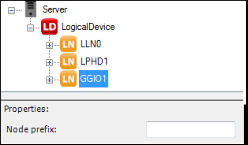
IEC 61850 Server
Quickstart

                   Fig. 1: 'Add Device' dialog
                   Now the IEC 61850 Server is inserted in the device tree.

4                                                3ADR010671, 4, en_US         2021/02/02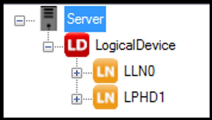
IEC 61850 Server
                                                                                                           Quickstart

                  Fig. 2: Device tree with IEC 61850 Server

Step 2: Add the   Open the editor for the configuration of the server via a double-click on the IEC 61850 Server in
Logical Device    the device tree.
to the server

                  Fig. 3: editor of the IEC 61850 Server
                  First a “Logical Device” is added to the server. The   “Logical Device ” is the instance of an
                  IED.
                  1.   Select the “Logical Device”
                  2.   Activate the “>” button

                  Together with the “Logical Device” the two LNC instances ( ) “LLN0” and “LPHD1” are added.
                  These two information objects are elements of every IED and can not be removed.

2021/02/02                                       3ADR010671, 4, en_US                                              5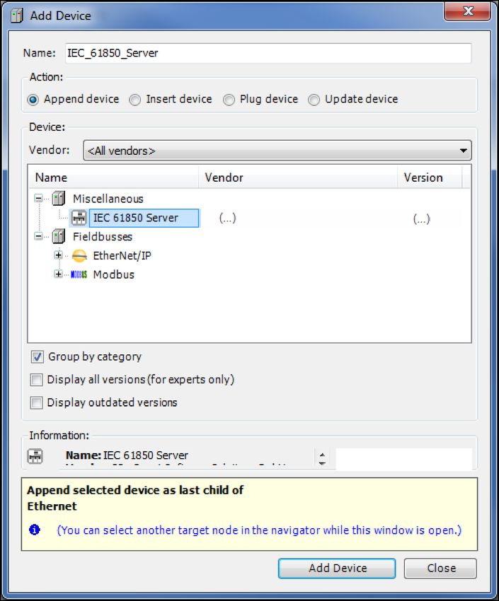
IEC 61850 Server
Quickstart

                   Fig. 4: Server with Logical Device, LLN0 and LPHD1

Step 3: Add
another LNC
instance to the
Logical Device
                   1.   Select the “Logical Device” below the server
                   2.   On the left-hand side select the “XCBR” LNC instance below “LN [Xxxx]-Switchgear”
                   3.   Activate the “>” button

                   Fig. 5: Adding the LNC instance 'XCBR'

Step 4: Expand     If you select the LNC instance on the right-hand side, all of the optional and obligatory CDCs
the “XCBR”         (data objects ) will be displayed on the left-hand side. .
LNC instance
with the
optional
“MaxOpCap”
CDC instance
                   1.   Select the “XCBR” LNC instance on the right-hand side
                   2.   Select the “MaxOpCap” CDC instance on the left-hand side
                   3.   Activate the “>” button

6                                                 3ADR010671, 4, en_US                                     2021/02/02
IEC 61850 Server
Quickstart
Fig. 6: XCBR1 with 'MaxOpCap' CDC
Step 5: Link an
attribute (DA) of
the IEC 61850
Server with a
CODESYS vari-
able
1. Select the desired attribute (in the example: “Server è LogicalDevice è XCBR1
è MaxOpCap è DA (ST I INT32) StVal ”)
2. Edit the CODESYS variable name in the input field “Monitoring Var” (in the example
Var_stVal) in the “Properties” section
The “Autom. declare” option must be activated, thus the variable is declared automatically as
global variable by theIEC 61850 Server. You can edit the initial value in the input field next to the
“Monitoring Var” field.
2021/02/02 3ADR010671, 4, en_US 7IEC 61850 Server
Quickstart
Fig. 7: Link of the attribute 'stVal' to the monitoring variable 'Var_stVal'
Step 6: Create a In this step you create a dataset (Compilation of data) for the IEC 61850 configuration created
dataset in the previous steps.
1. Open the “DataSet” tab
2. Activate the “New” button. The created “LLN0.dataSet_0” dataset is displayed in the
“DataSets” section.
3. Select the “LLN0.dataSet_0” DataSet
4. Select the “MaxOpCap” data object on the left-hand side (“Server è LogicalDevice
è LN XCBR1 è FC ST è DO MaxOpCap”)
5. Activate the “>” button.
8 3ADR010671, 4, en_US 2021/02/02IEC 61850 Server
Quickstart
Now the DataSet contains the data object “LogicalDevice/XCBR1.ST.MaxOpCap”
Fig. 8: 'DataSet' tab
Step 7: Create a In this step you assign a report to the defined DataSet. A report transports the data assigned via
Report a dataset to a connected client in the event of a trigger (see Ä Trigger Options).
1. Open the “Report” tab
2. Activate the “New ” button. The “RCB_1” is displayed in the “Reports” section. In the
“Name:” field you can change the name of the report.
3. Select the “LLN0.DataSet_0” dataset in the “DataSet” selection list
Fig. 9: 'Report' tab with created 'RCB' report
You set options about the reporting behavior in the “General options” section, you select the
events that trigger a report in the “Trigger Options” section (for more information about these
options see Ä Trigger Options).
2021/02/02 3ADR010671, 4, en_US 9IEC 61850 Server
Quickstart
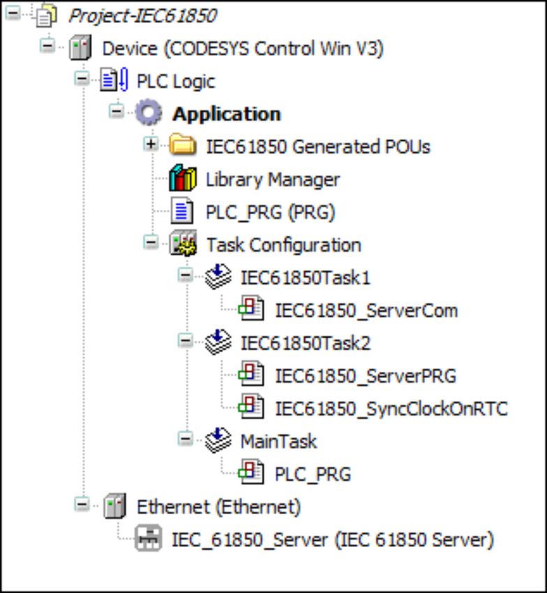
Step 8: Gen- The “Generate code” command of the menu “IEC61850” generates code from the created con-
erate code and figuration and puts it into the “IEC61850 Generated POUs” folder of the device tree.
load the applica-
tion to the PLC
Fig. 10: device tree with 'IEC61850 Generated POUs'
The global variable “Var_stVal” created in step 5 is listed in the “IEC61850_Generated_GVL”
global variables list.
Fig. 11: IEC61850_Generated_GVL with 'Var_stVal'
Subsequent compile the application via the “Build è Build” command.
Step 9: Con- If the application was finished successfully you create a connection to an IEC 61850 client in
necting with an this step. For this, login to the PLC and start the application via the “Start” command of the
IEC 61850 Client “Debug” menu. Now you connect an IEC 61850 client with the IEC 61850 Server. By the client
you can read out your IEC 61850 Server configuration and the configured DataSets und
Reports, as well as you can receive GOOSE messages and send GOOSE messages to the
server.
10 3ADR010671, 4, en_US 2021/02/02IEC 61850 Server
Editor of the IEC 61850 Server > Configuration
1.3 Editor of the IEC 61850 Server
1.3.1 IEC 61850 Editor
You open the editor of the IEC 61850 Server with the “Edit Object ” command of the “File ” cate-
gory or with a double-click on the device in the device tree.
If you move the mouse pointer over buttons, options or names of input fields in
this editor more information about the element is displayed by the tooltip.
The tabs of the editor::
● Ä Chapter 1.3.2.1 “Configuration” on page 11
● Ä Chapter 1.3.3 “DataSet” on page 21
● Ä Chapter 1.3.4 “Report” on page 22
● Ä Chapter 1.3.5 “GOOSE Publisher” on page 24
● Ä Chapter 1.3.6 “GOOSE Subscriber” on page 26
● Ä Chapter 1.3.7 “Information” on page 28
1.3.2 Configuration
1.3.2.1 Configuration
In the “Configuration” tab of the IEC 61850 editor you create, configure an parametrize the IED
from the pool of the existing LNC and CDC types.
Fig. 12: 'Configuration' tab
“Configuration” is split in 4 sections:
2021/02/02 3ADR010671, 4, en_US 11IEC 61850 Server
Editor of the IEC 61850 Server > Configuration
● Section and section are for creating the IEC 61850 Server. In section all of the
choices are displayed, which can be added to the instance currently focused or to the object
of the sever currently focused in section . In the default setting there is the Logical Device
( ) in section and the server ( ) in section . For more information see Ä Chapter
1.3.2.2 “Creation of the IEC 61850 Server” on page 12
● In the “Properties” section the following activities can be performed, depending on the
selected objects:
– Ä “Parametrization of the IEC 61850 Server” on page 15
– Ä “Entry of a device name for the Logical Device” on page 16
– Ä “Connecting an attribute (DA) with a CODESYS variable” on page 16
– Ä “Entry of a node prefix for LNC instances” on page 19
● is the status bar. For a more information see Ä Chapter 1.3.2.4 “Status bar”
on page 19.
1.3.2.2 Creation of the IEC 61850 Server
Adding instances
You add an element to the server or to the marked instance below the server by selecting the
element in section and activating the “>” button or by a double-click on the element
Removing instances
To delete instances below the server, mark the instance an activate the“IEC 61850 Server
Editor of the IEC 61850 Server > Configuration
Fig. 14: 'Configuration': List of the available LACS
If you mark a LNC instance in section 2 all mandatory and all optional CDC types (data object
) will be listed in section . The mandatory CDC types (Mod, Beh, Health, NamPlt, in the
example) are already contained in the LNC instance (LN GGIO1) and can not be removed.
Fig. 15: 'Configuration' list of the CDCs (DO) available for the GGIO1
The DOs include the attributes (DAs)
2021/02/02 3ADR010671, 4, en_US 13IEC 61850 Server
Editor of the IEC 61850 Server > Configuration
Fig. 16: 'Configuration': list of attributes (DA) of the added to the CDC 'DO AnIn'
The attributes of the server can be connected with CODESYS variables (see Ä “Connecting an
attribute (DA) with a CODESYS variable” on page 16).
1.3.2.3 Properties
: In the “Properties ” section of the Ä Chapter 1.3.2.1 “Configuration” on page 11 tab the fol-
lowing functions can be performed dependent on the marked object or the marked instance:
● Ä “Parametrization of the IEC 61850 Server” on page 15
● Ä “Entry of a device name for the Logical Device” on page 16
● Ä “Connecting an attribute (DA) with a CODESYS variable” on page 16
● Ä “Entry of a node prefix for LNC instances” on page 19
If you move the mouse pointer over an input field or the name of an input field,
you get a tooltip with a description in the window below the “Properties ” (see
the following figure).
14 3ADR010671, 4, en_US 2021/02/02IEC 61850 Server
Editor of the IEC 61850 Server > Configuration
Parametrization
of the IEC 61850
Server
Fig. 17: 'Properties' with tooltip of 'Max. client count'
Property Description
Server Name Name of the server,
IP I Subnetmask I Gateway Own IED IP address, I Subnetmask I own gateway address
Max.client count The maximum number of clients that can connect to the IED, possible
values: 1, 2, 3, 4, 5
Allowed IPs Allowed IPs for clients 1...5
default is 0.0.0.0, whereby an IP address that equals 0.0.0.0 means that no
IP address validity test will take place. If more than one client connection
was selected above, additional IPs must be configured for each one. As
soon as an IP address is parameterized with 0.0.0.0, testing for all con-
nected clients is deactivated.
2021/02/02 3ADR010671, 4, en_US 15IEC 61850 Server
Editor of the IEC 61850 Server > Configuration
Property Description
Time synchronisation Selection: SNTP
SNTP (default): SNTP time synchronization. In addition to activation, func-
tionality must be parameterized in the device's web-based management.
Currently, the SNTP time telegram does not use milliseconds, which means
accuracy is measured in 1 second increments.
1. Input field Time zone: Offset between Greenwich (GMT)- and the local
time (for Germany 1 h, for example). The value is limited between -12 an d
+ 14
2. Input field: DLS Mode: Ratio for the mode summer/winter time change-
over. Possible values:
● 0 = No automatic summertime/wintertime changeover
● 1 = Timeover from wintertime to summertime on last the Sunday in
March, changeover from summertime to wintertime on the last Sunday
in October
Task Prio I Interval Task
1.input field: entry of the priority,
2.input field: entry of the interval in ms
TCP KeepAlive[sec] The KeepAlive is to check the connection to the client.
Entry of a If the Logical Device is focused in the configured server you can entry a device name for the
device name for Logical Device in the 'Properties' section.
the Logical
Device
Connecting an
attribute (DA)
with a
CODESYS vari-
able
1. Select the attribute of a CDC instance below the server.
2. Enter the desired CODESYS variable name into the input field “Monitoring Var” in the
properties section.
Entry optionally an initial value into the input field right-side hand of the variable name.
In case of an attribute with RW-access, a “Control Variable” (writing access) can be entered in
addition to the “Monitoring Var” variable (reading access) . For a more detailed description
about reading and writing of variables at the IEC 61850 Server see Ä Chapter 1.4 “Reading and
Writing from CODESYS Variables ” on page 28. The monitoring and control variables declared
in the “Properties” section are displayed next to the respective attribute and at the superordi-
nated node “DO” of the server tree.
By activating the “Autom. declare ” checkbox the variable is declared by the IEC 61850 configu-
rator and stored in the “IEC61850_Generated_GVL” (of the “IEC61850 Generated POUs”
folder) after Ä Chapter 1.5.1.1 “Generate code” on page 29 of the IEC 61850 Server.
If you do not activate the “Autom. declare” checkbox you select the variable via
the input assistance ([F2)]) or you declare the variable yourself.
“Trigger option:” With the trigger options you set the attributes to select the events which might
trigger a report. The selected trigger option is displayed in the status bar. For a description of
the options see Ä status bar.
16 3ADR010671, 4, en_US 2021/02/02IEC 61850 Server
Editor of the IEC 61850 Server > Configuration
The trigger option determines whether the Ä Chapter 1.3.4 “Report”
on page 22, assigned to the Ä Chapter 1.3.3 “DataSet” on page 21, is sent
when the value of this attribute changes.
2021/02/02 3ADR010671, 4, en_US 17IEC 61850 Server
Editor of the IEC 61850 Server > Configuration
Fig. 18: 'Properties' for the attribute(DA) 'ctlNum', input fields: 'Monitoring Var' with 'Initvalue'
18 3ADR010671, 4, en_US 2021/02/02IEC 61850 Server
Editor of the IEC 61850 Server > Configuration
Fig. 19: 'Properties' of an attribute with RW-access: in addition input : 'Control Variable'
Entry of a node
prefix for LNC
instances
Fig. 20: 'Properties' of the LNC instance 'GGIO1' with 'Node prefix' input field
Here you enter a prefix for the selected LNC instance. The prefix is put in front of the LN name
in the server tree. The prefix is displayed in the Ä Chapter 1.3.2.4 “Status bar” on page 19,
too.
1.3.2.4 Status bar
In the status bar ( of the Ä Further information on page 11) of the IEC 61850 editor you find
object-specific detail information about the selected object.
Object informa-
tion: Server and
Logical Device
Fig. 21: Status bar for the Server
Only the information “Name” is displayed for the server and the Logical Device.
Object informa-
tion: LN
Fig. 22: Status bar for the LN instance 'LPHD'
2021/02/02 3ADR010671, 4, en_US 19IEC 61850 Server
Editor of the IEC 61850 Server > Configuration
Status Description
“Name” Name of the selected LN instance
“Description” Description of the selected LN instance
“Group” Associated group of the LN instance
Examples:
[Axxx]-Automatic
[Cxxx]-Control
[Gxxxx]-Generic
...
“Prefix” Prefix of the LNC instance, entered by the user
Object informa-
tion: Common
Data Class
Object (CDC
Object) Fig. 23: Status bar of the CDC instance 'Beh'
Status Description
“Name” Name of the attribute
“Description” Description of the selected CDC instance
“Option” Option of the selected CDC- instance
M = mandatory
O = optional
“CDC” Type of the selected CDC instance
“Instno” Instance number of the CDC instance.
Only optional CDCs can have instance numbers. If there is
only one optional CDC, it has no instance number. Otherwise
1 to n.
Objects with the 'mandatory' options are inserted automatically when adding the
Logical Device.
Object informa-
tion: Attribute
(DA)
Fig. 24: Status bar of the attribute 'q'
Status Description
“Name” Name of the attribute
“FC” Functional Constraint of the selected attribute
“Option” Option of the selcted attribute:
M = mandatory
O = optional
20 3ADR010671, 4, en_US 2021/02/02IEC 61850 Server
Editor of the IEC 61850 Server > DataSet
Status Description
“Type” Data type of the attribute
“Trigger Option” Trigger option of the attribute
dchg = data change
dupd = data update
qchg = quality change
= no trigger option
“Value” Associated variable
“Writeable” Access for the attribute
R = Read
W = Write
RW = Read and Write
1.3.3 DataSet
In this tab of the IEC 61850 editor you create and delete datasets, you assign attributes (DA)
and data objects (DO) to a dataset and you delete existing assignments.
Fig. 25: 'DataSet' tab with 'LLN0.DataSet_0' dataset and DAs 't' and 'ctlNum'
Structure of the Section displays the IEC 61850 Server created in the Ä Chapter 1.3.2.1 “Configuration”
tab on page 11 tab.
The sections and are for creating, editing and deleting of DataSets. In section the data-
sets are listed. In section the attributes and data objects of the dataset are listed, which is
marked in section .
For more information about section see Ä Chapter 1.3.2.4 “Status bar” on page 19.
2021/02/02 3ADR010671, 4, en_US 21IEC 61850 Server
Editor of the IEC 61850 Server > Report
NOTICE!
The order of the attributes of a DataSet is important for the receiving and the
sending of GOOSE messages. Type and order of the entries from sender and
recipient must be identical for GOOSE communication. For more information
about GOOSE communication see Ä Chapter 1.3.5 “GOOSE Publisher”
on page 24 and Ä Chapter 1.3.6 “GOOSE Subscriber” on page 26.
Buttons:
● “New”: Create a new dataset. This is displayed in the “DataSets” section and is named
“LLN0.DataSet_Suffix”. The suffix is incremented beginning with 0 (1. DataSet:
LLN0.DataSet_0 ...)
● “Delete”: Delete a dataset: Select the desired dataset in the “DataSets” section and activate
the “Delete”.button.
● “>”: Assign an attribute or a data object to the selected dataset. First select the dataset in
section 2 then select the attribute or the data object in section 1 and activate the “>” button.
● “IEC 61850 Server
Editor of the IEC 61850 Server > Report
Table 1: General settings
Setting possibility Description
“Buffersize” Buffer size of buffered reports (in bytes).
“Name” Unique Report Block name within the logical node.
“Description” Description of the report block
“Integrity Period [ms]” Stealthy general interrogation. After this time the referenced dataset will be
actuated.
Time (ms) between two messages
The messages are transferred cyclic, independent from other events.
“Buffered” Enable / disable the report buffering.
A buffered report stores the data, even if there's no connection to the client.
In the case of an unbuffered report, the messages will get lost, if there is no
connection to the client.
“Buffer Time [ms]” Buffer time is the amount of time that the server waits to transfer a report
after a given event occurs. Events that occur during this time period are
collected and then transferred as a batch.
If the buffer time is 0, the telegram will be sent immediately. For example, if
the buffer time 10s the telegram will be sent after this time period or when
the value changes the second time.
“Config Revision” Versioning is used to identify whether or not a member was deleted from a
dataset or whether member order has changed. Such changes cause
values to not be transferred, or cause values to be in a different location
within the report. Such an event is communicated to the client with a new
version number.
Since all datasets are firmly defined, this identifier does not apply to the
solution described here.
“DataSet” Data set reference
Section is for the setting of the following options:
● “General options”: Control of the reporting behavior. An activated checkbox means, that the
information is transferred by the message
● “Buffered specific options”: can be activated, if the option “Buffered:” (in section 2) is acti-
vated.
● “Trigger options”: Determining of attributes to select the events which may trigger a mes-
sage.
If the checkbox is activated the information will be transferred by the message.
Table 2: General options
Setting Possibility Description
“Send Config Revision” 'Config Revision' information
“Send Data Reference” Enable/disable to transfer the complete reference information,
for example: LogicalDevice/GGIO1.ST.Mod.ctlNum
“Send DataSet name” Enable/disable to transfer the dataset name
“Send Reason for Inclusion” Enable/disable to transfer the reason of transmission for each attribute
“Send Sequence Number” Enable/disable to transfer a unique sequence number for each message
“Send Time Stamp” Enable/disable to transfer the timestamp of transmission for each message
2021/02/02 3ADR010671, 4, en_US 23IEC 61850 Server
Editor of the IEC 61850 Server > GOOSE Publisher
Table 3: Buffered specific options
Setting Possibility Description
“ Send Entry ID” Enable/disable to transfer the 'Entry ID'
“Send Buffer overflow” Enable/disable to transfer the message if a buffer overflow occurs.
Table 4: Trigger options
Setting Possibility Description
“Data Change ” Enable/disable to trigger the report if a 'data change' event occured
“Data Update” Enable/disable to trigger the report if a 'data update' event of an attribute
occured.
“Quality Chance” Enable/disable to trigger the report if a 'quality change' event of an attribute
occured
“Integrity” Enable/disable the cyclic transmission of the report independent of any
datachanges (Stealthy general interrogation) .
The time period has to be defined in the “Integrity Period” general setting.
“General Interrogation”
Create a report 1. Activate the “New” button
control block
2. Select the desired dataset from the “DataSet” selection list
and assign it to
a dataset
1.3.5 GOOSE Publisher
In the “GOOSE Publisher” tab of the IEC 61850 editor you create, edit and delete GOOSE mes-
sages. If a value changes in the selected dataset, a GOOSE message is sent.
Fig. 27: 'GOOSE Publisher' tab
NOTICE!
The order of the attributes of a DataSet is important for the receiving and the
sending of GOOSE messages. Type and order of the entries from sender and
recipient must be identical for GOOSE communication.
24 3ADR010671, 4, en_US 2021/02/02IEC 61850 Server
Editor of the IEC 61850 Server > GOOSE Publisher
NOTICE!
To receive a GOOSE message from an IED, sender an recipient must have the
identical settings in the following input fields:
– “APPID”
– “GOOSE-ID”
– “Dataset structure (with regard to order and data type of the attributes)”
After the dataset is sent, it is sent again after time interval of 500 ms. The repeat time then dou-
bles and the dataset is sent again. The dataset is sent repeatedly until the value set in the
“Repeat Time” input field is reached. The dataset is then sent again at the Repeat Time interval.
Sections of the tab:
: List of the GOOSE control blocks (GCB).
A GOOSE control block is a GOOSE message.
Buttons
● “New”: Create a new GOOSE cntrol block
● “Delete”: Delete the selected GOOSE control block.
: General settings:
Table 5: General
Setting Description
“Name” Name of the GOOSE control block., editable
“Description” Description of the GOOSE control block
“GOOSE-ID” Unique character string of the GOOSE control block, editable
“DataSet” Dataset sent as a GOOSE message.
“MAC” Multicast addressing
Multicast addressing is used to send GOOSE messages. Addressing
allows a entire group of devices to exchange data with each other.
Requirement: unique address allocation of the different device groups.
Valid range of values: 01-0C-CD-01-00-00....01-0C-CD-01-01-FF
“APPID” Application-ID
Number for the system-wide unique identification of a GOOSE control
block. To exchange GOOSE telegrams, this number must be identical for
sender and recipient.
Valid range of values: 0 ... 4095
“Source Address (MAC)” “Browse...” button: looks for an Ethernet Port in the network. Requirement:
an existing network path to the PLC (see ).
: GOOSE Publisher settings
Table 6: Publisher
Setting Description
“Needs Commissioning” Indicates whether the control block must be checked
Value is provided from the configurator. Usage of the flag is customer-spe-
cific.
“DataSet Config Revision” Integer value with the version of the GOOSE control block.
“Repeat Time (T0)[ms]” Time interval during which the GOOSE telegram is valid.
2021/02/02 3ADR010671, 4, en_US 25IEC 61850 Server
Editor of the IEC 61850 Server > GOOSE Subscriber
Setting Description
“Max. Time [ms]” Source supervision time (heartbeat cycle)
“Min. Time [ms]” Maximum permissible send delay time of a data change
“VLAN” 'Virtual Local Area Network'
Logical subnet within a physical network. Multicast messages can be
passed through and filtered. The configuration is done in managed
ETHERNET switches.
If the “VLAN” checkbox is activated, values can be entered into the “VLAN-
ID” and “VLAN-Priority” input fields, concerning the passed through of mas-
sages via switches.
“VLAN-ID” A value of 0 is a non-configured VLAN in which the switch performs no fil-
tering. This value is recommended when no logical network should be set
up.
Valid range of values: 0 ... 4095.
“VLAN-Priority” Messages within a managed ETHERNET switch can be forwarded
depending on the priority
Valid range of values: : 0 … 7.
Default value for GOOSE: 4.
: Content of the Dataset assigned to the GOOSE control block.
Create an 1. Activate the “New” button
GOOSE control
2. Select the desired dataset from the “DataSet” selection list.
block and
assign it to a
dataset
1.3.6 GOOSE Subscriber
In this tab of the IEC 61850 editor you make settings for the receiving of GOOSE messages.
Fig. 28: 'GOOSE Subscriber' tab
NOTICE!
The order of the attributes of a dataset is important for the receiving and the
sending of GOOSE messages. Type and order of the entries from sender and
recipient must be identical for GOOSE communication.
26 3ADR010671, 4, en_US 2021/02/02IEC 61850 Server
Editor of the IEC 61850 Server > GOOSE Subscriber
NOTICE!
To receive a GOOSE message from an IED, sender an recipient must have the
identical settings in the following input fields:
– “APPID”
– “GOOSE-ID”
– “DataSet” structure (with regard to order and data type of the attributes)
Sections of this tab:
: List of the GOOSE control blocks (GCB)
Buttons
● “New”: Create a new GOOSE control block
● “Delete”: Delete the selected GOOSE control block.
● “Import”: Import a GOOSE control block in the SCL format
: General settings:
Table 7: General
Setting Description
“Name” Name of the GOOSE control block., editable
“Description” Description of the GOOSE control block
“GOOSE-ID” Unique character string of the GOOSE control block, editable
“DataSet” Dataset received as a GOOSE message.
“MAC” Multicast addressing
Multicast addressing is used to send GOOSE messages. Addressing
allows a entire group of devices to exchange data with each other.
Requirement: unique address allocation of the different device groups
Valid range of values: 01-0C-CD-01-00-00....01-0C-CD-01-01-FF
“APPID” Application-ID
Number for the system-wide unique identification of a GOOSE control
block. To exchange GOOSE telegrams, this number must be identical for
sender and recipient.
Valid range of values: 0 ... 4095
“Source Address (MAC)” “Browse...” button: looks for an Ethernet Port in the network. Requirement:
an existing network path to the PLC (see ).
: List to assign GOOSE messages to global variables.
All attributes within the selected dataset are listed in this list. You can assign incoming GOOSE
messages to global CODESYS variables. For this, select the desired attribute in the list and edit
the name of a global variable in the “Varname” column. If you edit a new variable name a global
variable will be created, if you activate the “Use default name” checkbox, a variable name is
generated automatically. This variable will be written by incoming GOOSE messages.
The variables will be stored “IEC61850_Generated_GVL” (of the “IEC61850 Generated POUs”
folder) after Ä generating the code of the IEC 61850 Server.
Fig. 29: Example for the variable list
2021/02/02 3ADR010671, 4, en_US 27IEC 61850 Server
Reading and Writing from CODESYS Variables > Information
Create a GOOSE 1. Activate the “New” button
control block
2. Select the desired dataset from the “DataSet” selection list
and assign it to
a dataset
1.3.7 Information
This tab of the IEC 61850 editor shows information on the IEC 61850 Server
Fig. 30: 'Information' tab'
1.4 Reading and Writing from CODESYS Variables
Monitoring For reading in monitoring direction you connect an attribute (DA) with R-access (read) a
direction, CODESYS monitoring variable (see Ä “Parametrization of the IEC 61850 Server” on page 15).
reading
The following dataflow variants are possible:
● from the IEC 61850 Server to the connected IEC 61850 Client to read a CODESYS moni-
toring variable
● from an I/O module to the IEC 61850 Server to the connected IEC 61850 client to read an
I/O module pin.
Control direc- For writing in control direction you connect an attribute (DA) with W-access (write) to a
tion, writing CODESYS control variable (see Ä “Parametrization of the IEC 61850 Server” on page 15).
The following dataflow variants are possible:
● from a connected IEC 61850 client to the IEC 61850 Server to write a CODESYS-variable
● form the connected IEC 61850 client to the IEC 61850 Server to an I/O module to write the
I/O module pins.
Monitoring It may be the case that the IEC 61850 client will read the monitoring variable of an attribute and
direction + con- will write the control variable of the same attribute. Monitoring variable and control variable must
trol direction, not be the sameCODESYS variable.
reading an
In monitoring direction the data flow takes place from the IEC 61850 Server to the connected
writing
IEC 61850 client to read the CODESYS monitoring variable.
In control direction the data flow takes place from the connected IEC 61850 client to the IEC
61850 Server to write the CODESYS control variable.
28 3ADR010671, 4, en_US 2021/02/02IEC 61850 Server
Menu Command sorted by Categories > IEC61850
1.5 Menu Command sorted by Categories
1.5.1 IEC61850
1.5.1.1 Generate code
Symbol:
On activating the “Generate code” command of the “IEC61850” category the code generation is
started and the generated IEC 61850 code is stored in the folder “IEC61850 Generated POUs”
in the device tree.
1.5.1.2 Export Server
This command of the “IEC61850” category exports the current configuration. In the “Safe as ”
dialog select the format filter:
● XML Files: for IEC 61850 format with all specific data, variable mapping, for example
● SCL-Files: for IEC 61850 format to export data to other IEC 61850 tools
If you have changed the configuration since the latest code generation, you will be asked
whether new code should be generated before export.
1.5.1.3 Import Server
This command of the “IEC61850” category discards the current configuration and imports an
new configruation. In the “Save as ” dialog select the format filter:
● XML Files: for IEC 61850 format with all specific data, variable mapping, for example
● SCL Files: for IEC 61850 format to import data from other IEC 61850 tools
1.5.1.4 Options
The “Options” command of the “IEC61850” category opens a dialog for the setting of different
display options for the IEC 61850 configurator.
Option Description
“Show FC besides data attribute” Display option, shows functional constraint of attribute as a comment.
“Show type besides data attribute” Display option, shows type of attribute as a comment
“Show trigger option besides data Display option, shows trigger option of attribute as a comment
attribute”
“Show description besides data Display option, shows description of attribute as a comment
objects”
“Enable SCL Private block”
“Select all Data Objects ” Debug-Option: Selection of all data objects (DO)
“Select all Data Attributes” Debug-Option: Selection of all data attributes (DA)
1.5.1.5 Reset
This command of the “IEC61850” category deletes the whole current configuration and all
objects of the current application created via the “Generate code” command.
2021/02/02 3ADR010671, 4, en_US 29IEC 61850 Server
Logical Name Classes (LNC) > IEC61850
1.6 Logical Name Classes (LNC)
The following LNCs are available for the configuration of the IEC 61850 Server
Name Description
Automatic Control Functions
ATCC Automatic tap changer controller
Control
CALH Alarm handling
CCGR Cooling group control
Generic Functions
GAPC Generic automatic process control
GGIO Generic process I/O
GSAL Generic security application
System
LLN0 Logical Node Zero
LPHD Physical device information
Metering and measurement
MMTR Metering
MMXN Non phase related Measurement
MMXU Measurement
MSQI Sequence and imbalance
MSTA Metering Statistics
Protection
PDIF Differential
PFRC Rate of change of frequency
PHAR Harmonic restraint
PHIZ Ground detector
PIOC Instantaneous overcurrent
PMRI Motor restart inhibition
PMSS Motor starting time supervision
PTOV Overvoltage
Sensors and monitoring
SARC Monitoring and diagnostics for arcs
SIMG Insulation medium supervision (gas)
SIML Insulation medium supervision (liquid)
Instrument transformers
TCTR Current transformer
TVTR Voltage transformer
Wind power plant (IEC61400-25)
WALM Wind power plant alarm information
WAPC Wind power plant active power control
30 3ADR010671, 4, en_US 2021/02/02IEC 61850 Server
IEC 61850 Functionalities > IEC61850
Name Description
WCNV Wind turbine converter information
WGEN Wind turbine generator information
WMET Wind power plant meteorological information
WNAC Wind turbine nacelle information
WROT Wind turbine rotor information
WAPC Wind power plant reactive power control information
WOW Wind turbine tower information
WTRF Wind turbine transformer information
WTRM Wind turbine transmission information
WTUR Wind turbine general information
WYAY Wind turbine yawing information
X-Switchgear Functions
XCBR Circuit Breaker
XSWI Circuit Switch
Y-Power Transformers
YEFN Earth fault neutralizer (Petersen Coil)
YLTC Tap Changer
YPSH Power Shunt
YPTR Power Transformer
Further power system equipment
ZAXN Auxiliary network
ZBAT Battery
ZCAP Capacitor Bank
ZCON Converter
ZGEN Generator
ZGIL Gas Insulated Line
ZLIN Power Overhead Line
ZMOT Motor
ZREA Reactor
ZRRC Rotating reactive component
ZSAR Surge arrestor
ZTCF Thyristor controlled frequency converter
ZTCR Thyristor controlled reactive converter
1.7 IEC 61850 Functionalities
Models Con-
formance
2021/02/02 3ADR010671, 4, en_US 31IEC 61850 Server
IEC 61850 Functionalities > IEC61850
Functionality Support Comment
Logical device yes
Logical node yes
Data yes
DataSet yes
Substitution yes
Setting group control no
Reporting
Buffered report control yes
Sequence number yes
Report time stamp yes
Reason for inclusion yes
DataSet name yes
Data reference yes
Buffer overflow yes
Entry-ID yes
Buffer Time yes
Integrity Period yes
General Interrogation yes
Config Revision yes
Unbuffered report control yes
Sequence number yes
Report time stamp yes
Reason for inclusion yes
DataSet name yes
Date reference yes
Buffer Time yes
Integrity Period yes
General Interrogation yes
Config Revision yes
Logging no
Log Control no
Log no
Control yes Only Operate
GOOSE yes
GSSE no
Multicast SVC no
Unicast SVC no
Time yes
File Transfer no
Maximum number of simultaneously client connections 5 Parameter in the configu-
rator. 1...5
32 3ADR010671, 4, en_US 2021/02/02IEC 61850 Server
IEC 61850 Functionalities > IEC61850
Functionality Support Comment
Maximum MMS PDU size 45 000
Time synchronisation yes SNTP
SCL File support yes Ex-/Import in CODESYS
IEC 61850 Server TOOL
Service Con-
formance
Table 8: Server
Sevices Support Comment
ServerDirectory yes
Table 9: Application association
Sevices Support Comment
Associate yes
Abort yes
Release yes
Table 10: Logical Device
Sevices Support Comment
LogicalDeviceDirectory yes
Table 11: Logical Node
Sevices Support Comment
LogicalNodeDirectory yes
GetAllDataValues yes
Table 12: Data
Sevices Support Comment
GetDataValues yes
SetDataValues yes
GetDataDirectory yes
GetDataDefinition yes
Table 13: DataSet
Sevices Support Comment
GetDataSetValues yes
SetDataSetValues yes
CreateDataSet no
DeleteDataSet no
GetDataSetDirectory yes
2021/02/02 3ADR010671, 4, en_US 33IEC 61850 Server
IEC 61850 Functionalities > IEC61850
Table 14: Substitution
Sevices Support Comment
SetDataValues yes
Table 15: Reporting
Sevices Support Comment
Buffered report control block (BRCB)
Report yes
data-change (dchg) yes
qchg-change (qchg) yes
data-update (dupd) yes
GetBRCBValues yes
SetBRCBValues yes
Unbuffered report control block (URCB)
Report yes
data-change (dchg) yes
qchg-change (qchg) yes
data-update (dupd) yes
GetURCBValues yes
SetURCBValues yes
Table 16: Generic substation event model (GSE)
Sevices Support Comment
GOOSE-CONTROL-BLOCK
SendGOOSEMessage yes
GetReference no
GetGOOSEElementNumber no
GetGoCBValues yes
SetGoCBValues yes
GSSE-Control-Block
SendGSSEMessage no
GetReference no
GetGSSEElementNumber no
GetGsCBValues no
SetGsCBValues no
Table 17: Control
Sevices Support Comment
Select no
SelectWithValue no
Cancel no
34 3ADR010671, 4, en_US 2021/02/02IEC 61850 Server
IEC 61850 Functionalities > IEC61850
Sevices Support Comment
Operate yes
Command-Termination no
TimeActivated-Operate no
Table 18: Time
Sevices Support Comment
Time resolution of internal 7 nearest power of 10 ms
clock
Time accuracy of internal TL (ms) (low accuracy) T3 < 7 (only Ed2)
clock
T0 (ms) (Index
—
2 Index
A IEC 61850 Server
Add add . . . . . . . . . . . . . . . . . . . . . . . . . . . . . . . . . . . 3
IEC 61850 Server . . . . . . . . . . . . . . . . . . . . . . . . 3 Configuration . . . . . . . . . . . . . . . . . . . . . . . . . . . 11
creation . . . . . . . . . . . . . . . . . . . . . . . . . . . . . . . 12
C DataSet . . . . . . . . . . . . . . . . . . . . . . . . . . . . . . . 21
Configuration delete . . . . . . . . . . . . . . . . . . . . . . . . . . . . . . . . 29
IEC 61850 Server . . . . . . . . . . . . . . . . . . . . 11, 12 Editor . . . . . . . . . . . . . . . . . . . . . . . . . . . . . . . . . 11
Control direction functionalities . . . . . . . . . . . . . . . . . . . . . . . . . . 31
IEC 61850 server . . . . . . . . . . . . . . . . . . . . . . . 28 Generate code . . . . . . . . . . . . . . . . . . . . . . . . . 29
Control variable GOOSE Publisher . . . . . . . . . . . . . . . . . . . . . . . 24
IEC 61850 Server . . . . . . . . . . . . . . . . . . . . . . . 14 GOOSE Subscriber . . . . . . . . . . . . . . . . . . . . . . 26
D Import Server . . . . . . . . . . . . . . . . . . . . . . . . . . 29
DataSet Options . . . . . . . . . . . . . . . . . . . . . . . . . . . . . . . 29
IEC 61850 Server . . . . . . . . . . . . . . . . . . . . . . . 21 Properties . . . . . . . . . . . . . . . . . . . . . . . . . . . . . 14
Delete Quickstart . . . . . . . . . . . . . . . . . . . . . . . . . . . . . . 3
IEC 61850 Server . . . . . . . . . . . . . . . . . . . . . . . 29 Reset . . . . . . . . . . . . . . . . . . . . . . . . . . . . . . . . 29
status bar . . . . . . . . . . . . . . . . . . . . . . . . . . . . . 19
E Trigger option . . . . . . . . . . . . . . . . . . . . . . . . . . 19
Editor variable . . . . . . . . . . . . . . . . . . . . . . . . . . . . . . . 14
IEC 61850 Server . . . . . . . . . . . . . . . . . . . . . . . 11 IEC 61850 Sever
Export Server Information . . . . . . . . . . . . . . . . . . . . . . . . . . . . 28
IEC 61850 . . . . . . . . . . . . . . . . . . . . . . . . . . . . . 29 Import Server
G IEC 61850 . . . . . . . . . . . . . . . . . . . . . . . . . . . . . 29
Generate code L
IEC 61850 Server . . . . . . . . . . . . . . . . . . . . . . . 29 LNC
GOOSE Publisher IEC 61850 server . . . . . . . . . . . . . . . . . . . . . . . 30
IEC 61850 Server . . . . . . . . . . . . . . . . . . . . . . . 24 Logical Name Class (LNC)
GOOSE Subscriber IEC 61850 server . . . . . . . . . . . . . . . . . . . . . . . 30
IEC 61850 Server . . . . . . . . . . . . . . . . . . . . . . . 26
M
I Monitoring direction
IEC 61850 IEC 61850 server . . . . . . . . . . . . . . . . . . . . . . . 28
Export Server . . . . . . . . . . . . . . . . . . . . . . . . . . 29 Monitoring variable
write . . . . . . . . . . . . . . . . . . . . . . . . . . . . . . . . . 28 IEC 61850 Server . . . . . . . . . . . . . . . . . . . . . . . 14
IEC 61850 server
control direction . . . . . . . . . . . . . . . . . . . . . . . . . 28 O
Logical Name Classes (LNC) . . . . . . . . . . . . . . 30 Options
monitoring direction . . . . . . . . . . . . . . . . . . . . . . 28 IEC 61850 Server . . . . . . . . . . . . . . . . . . . . . . . 29
read . . . . . . . . . . . . . . . . . . . . . . . . . . . . . . . . . . 28 P
Report . . . . . . . . . . . . . . . . . . . . . . . . . . . . . . . . 22
Parametrization
RW . . . . . . . . . . . . . . . . . . . . . . . . . . . . . . . . . . 28 IEC 61850 Server . . . . . . . . . . . . . . . . . . . . . . . 14
36 3ADR010671, 4, en_US 2021/02/02Index
Properties
IEC 61850 Server . . . . . . . . . . . . . . . . . . . . . . . 14
Q
Quickstart
IEC 61850 Server . . . . . . . . . . . . . . . . . . . . . . . . 3
R
Read
IEC 61850 server . . . . . . . . . . . . . . . . . . . . . . . 28
Report
IEC 61850 server . . . . . . . . . . . . . . . . . . . . . . . 22
Reset
IEC 61850 Server . . . . . . . . . . . . . . . . . . . . . . . 29
S
status bar
IEC 61850 Server . . . . . . . . . . . . . . . . . . . . . . . 19
T
Trigger option
IEC 61850 Server . . . . . . . . . . . . . . . . . . . . . . . 19
V
Variable
IEC 61850 Server . . . . . . . . . . . . . . . . . . . . . . . 14
W
Write
IEC 61850 server . . . . . . . . . . . . . . . . . . . . . . . 28
2021/02/02 3ADR010671, 4, en_US 37—
ABB Automation Products GmbH
Eppelheimer Str. 82
69123 Heidelberg, Germany
Telephone: +49 (0)6221 701 1444
3ADR010671, 4, en_US
Fax: +49 (0)6221 701 1382
E-mail: plc.support@de.abb.com
abb.com/plc
—
© Copyright 2021 ABB.
We reserve all rights in this document and in the information contained therein. Reproduction, use or disclosure to third parties without express
authority is strictly forbidden.You can also read