IColor Tile MX Precision-controlled direct-view interior LED panel with dynamic color light
←
→
Page content transcription
If your browser does not render page correctly, please read the page content below
iColor Tile MX
Precision-controlled direct-view interior LED panel with dynamic color light
iColor Tile MX
Precision-controlled direct-view interior LED panel with
dynamic color light
iColor Tile MX is a full-color LED light panel for creating stunning light art and accents in a variety of surface-
mounted and recessed applications. Each 23.5 x 23.5 in (597 x 597 mm) panel has 144 individually addressable nodes
to enable an infinite variety of effects at an unprecedented level of fine-grained control and intricacy.
• An innovative canvas — With 144 individually
addressable, high-intensity, full-color LED nodes,
iColor Tile MX can serve as a canvas for creative
lighting designs, effects, animation, and large-scale
video displays.
• Seamless effects — iColor Tile MX is a base unit
Photography: Nicasa & Partners
for indoor applications, ideal for wall and ceiling
installations. Install behind a custom panel, or use
the available impact-resistant, translucent white
diffuser lens for seamless, uniform optical effects.
• Highly consistent color — Optibin, our
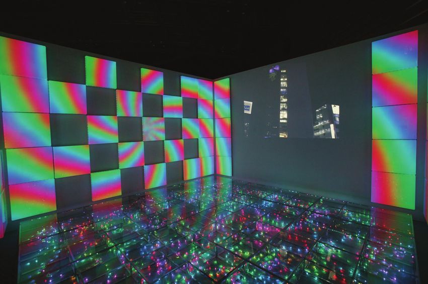
A total of 113 iColor Tile fixtures created a checkerboard-
proprietary binning optimization process, ensures
like canvas at the World Lighting Fair in Tokyo, Japan.
optimal color consistency from fixture to fixture. Morphing colors, patterns, and animations were displayed
• Versatile mounting options — Designed for recess across the fixtures’ 16,272 individually controllable, full-
color LED nodes.
and surface mounting on walls or ceilings. Capable
of retrofitting ceiling tiles. Standard leader cables • Quick setup for complex and large-scale
of 25 ft (7.6 m), 50 ft (15.2 m), and 100 ft (30.5 installations — Each iColor Tile MX fixture offers
m) let you position power / data supplies at an a pre-configured, 12 x 12 grid of 144 LED nodes,
appropriate distance from fixtures. with a fixed pixel pitch of 2 in (51 mm) on center.
• Industry-leading controls — Works with Philips Fixtures can be installed flush to extend consistent
full range of controllers, including Video System pixel pitch across multiple tiles. Fixtures can be
Manager, Light System Manager, iPlayer 3, or third- easily leveled and installed using the included wall-
party controllers. mounting cleat or mounting through-holes in the
fixture housing.
Superior Light Output
Each iColor Tile MX fixture
produces full-color light
output of 559 nits.
2 iColor Tile MX Powercore Product Guide
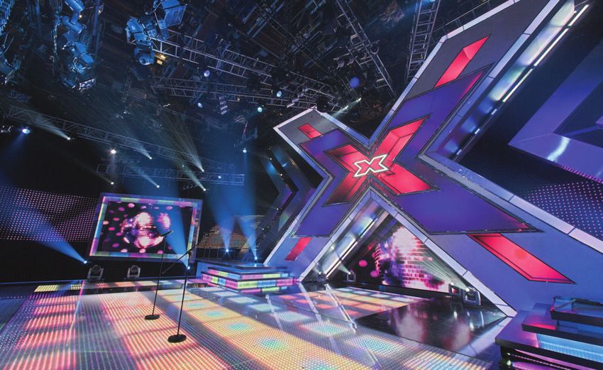
The X Factor in Direct-View LED Lighting
                                                     The US may have American Idol, but The X Factor — created by Idol judge Simon
                                                     Cowell — rules the airwaves in the UK. With an estimated 10 million regular
                                                     viewers, the talent search program is one of the UK’s top-watched entertainment
                                                     shows. Its vibrant set combines several applications of LED technology to stellar
                                                     effect.
                                                     Designers Dave Davey and Christopher George conceptualized an LED floor that
                                                     would generate dynamic effects to uniquely complement the action on stage.
                                                     More than 170 iColor Tile fixtures were installed beneath the slightly frosted stage
                                                     floor, making each fixture’s 144 full-color nodes visible for crisp definition. The
                                                     approximately 25,000 individually controllable iColor Tile nodes are collectively
                                                     capable of displaying sophisticated designs, patterns, and video across the entire floor.
                                                     The iColor Tile fixtures are controlled by Video System Manager (VSM), a
                                                     sophisticated  Ethernet-based lighting controller and video server from Philips
                                                     Color Kinetics. Video content was generated using a third-party video creation and
                                                                                                                 editing software system,
                                                                                                                 then downloaded to the
                                                                                                                 Video System Engine, the
                                                                                                                 hardware component
                                                                                                                 of VSM responsible for
                                                                                                                 streaming video to the
                                                                                                                 iColor Tile fixtures.
                                                                                                                   “The extraordinary visual
                                                                                                                   impact of Color Kinetics
                                                                                                                   systems coupled with
                                                                                                                   their ease of control
                                                                                                                   and rugged, durable
                                                                                                                   nature makes them an
                                                                                                                   ideal solution for The X
                                                                                                                   Factor set,” said lighting
                                                                                                                   director Dave Davey.
                                                                                                                   “LED technology allows
                                                                                                                   a completely new level
                                                                                                                   of creative flexibility in
                                                                                                                   lighting design, and the
                                                                                                                   saturated colors translate
                                                                                                                   very effectively on
                                                                                                                   camera.”
                                                                                                                 Because the entire
Lighting Design: Dave Davey and Christopher George                                                               system is under digital
Photography: Louise Stickland
                                                     control, the set designers and lighting director can dynamically change or fine-tune
                                                     the appearance of The X Factor set on the fly. And because their LEDs radiate no
                                                     heat, iColor Tile fixtures can be positioned virtually anywhere on the set . . . even
                                                     underfoot!

                                                                                                     iColor Tile MX Powercore   Product Guide   3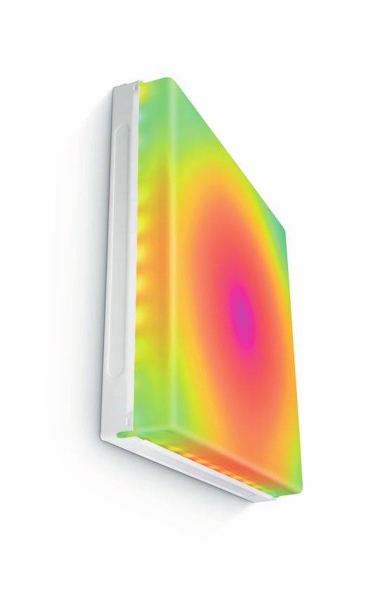
Specifications
Due to continuous improvements and innovations, specifications may change without notice.

                                                                                                                                 23.5 in Square
    Item             Specification                 Details                                                                         (597 mm)
                     Lumen Maintenance*            50,000+ hours L50 @ 50° C (full output)
    Output
                     LED Channels                  Red / Green / Blue
                                                                                                                                                    Impact Resistant
                     Input Voltage                 7.5 VDC via PDS-60ca and sPDS-60ca
                                                                                                                                                      Diffuser Lens
    Electrical       Power Consumption             62 W maximum at full output, steady state
                     Power Factor                  .98 @ 120 VAC
                                                   sPDS-480ca 7.5V (Ethernet)
                     Interface
                                                   PDS-60ca 7.5V (Pre-programmed or DMX / Ethernet)
    Control                                        Philips full range of controllers, including Video System Manager
                     Control System                Pro, Light System Manager, and iPlayer 3, or third-party
                                                   controllers
                     Dimensions
                                                   23.5 x 23.5 x 2 in (597 x 597 x 51 mm), without lens
                     (Height x Width x Depth)
                                                                                                                         2 in
                     Weight                        23 lb (10.4 kg) Tile   5 lb (2.3 kg) Lens                           (51 mm)                        4.125 in
                                                                                                                                                     (105 mm)
                     Housing                       Sheet metal, white powder-coated finish
                                                   Impact-resistant copolyester with carbon steel mounting
                     Lens
                                                   hardware

    Physical         Fixture Connections           Integrated 3-pin connector
                                                   -4° – 122° F (-20° – 50° C) Operating
                                                   ≥ 32° F (≥ 0° C) Handling
                     Temperature Ranges
                                                   -4° – 122° F (-20° – 50° C) Startup
                                                   -22° – 185° F (-30° – 85° C) Storage
                     Humidity                      0 – 95%, non-condensing
                     Maximum Fixtures Per          PDS-60ca 7.5V: 1
                     Power / Data Supply           sPDS-480ca 7.5V: 8

    Certification    Certification                 UL / cUL, FCC Class A, CE
    and Safety       Environment                   Dry Location, IP20
*		L50 = 50% lumen maintenance (when light output drops below 50% of initial
   output). Ambient luminaire temperatures specified. Lumen maintenance calculations                                               20 in
   are based on lifetime prediction graphs supplied by LED source manufacturers.                                                 (508 mm)
   Calculations for white-light LED fixtures are based on measurements that comply with IES LM-80-08
   testing procedures. Refer to www.philipscolorkinetics.com/support/appnotes/lm-80-08.pdf for more
   information.
                                                                                                                                       Wall Cleat

Photometrics
Luminance (nits)
    Lensing                          On-Axis Candela         Viewing Angle
    No lens                          559 cd / m2             110°
    Frosted lens                     227 cd / m2             120°

4          iColor Tile MX Powercore   Product Guide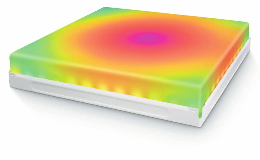
Fixtures and Power / Data Supplies
                                                     iColor Tile MX fixtures are part of a complete system which includes:
                                                     • One or more power / data supplies
                                                     • Two Leader Cables to attach each iColor Tile MX fixture to a power / data supply
Included in the box                                  • Optional white translucent lenses for diffusing fixtures’ light output
iColor Tile MX fixture
                                                     • Any Philips controller, including Video System Manager Pro, Light System Manager,
Mounting alignment cleat
                                                       and iPlayer 3, or any third-party controller
(6) Corner clips
                                                        Item                    Type                                        Item Number       Philips 12NC

                                                        iColor Tile MX          White                                     101-000071-00     910503701017
                                                        iColor Tile MX Lens     White      Translucent                    101-000044-00     910503700564
                           iColor Tile MX fixtures
                                                                                Black      25 ft (7.6 m)                  108-000045-00     910503700696
                                   and accessories
                                                        Leader Cables           Black      50 ft (15.2 m)                 108-000045-01     910503700697
                                                                                Black      100 ft (30.5 m)                108-000045-02     910503700698

                                                                                Pre-programmed                            109-000015-00     910503700093
                                                        PDS-60ca 7.5V
                             Power / data supplies                              DMX / Ethernet                            109-000015-03     910503700094
                                                        sPDS-480ca 7.5V         Ethernet                                  109-000022-00     910503700107
                                                                                                           Use Item Number when ordering in North America.

                                                                                                              iColor Tile MX Powercore   Product Guide       5
Installation iColor Tile MX is a direct-view light panel for creating stunning light art, accent lighting, and video displays in a variety of surface-mounted and recessed applications. iColor Tile MX is a 23.5 x 23. 5 in (597 x 597 mm) panel with 144 individually addressable nodes for intricate, fine-grained control. Each panel can be installed with a white translucent lens, or behind a scrim or other translucent surface. Because of their potential complexity, iColor Tile MX installations require upfront planning for configuring, positioning, and mounting fixtures. Planning includes understanding how to position fixtures in relation to power / data supplies and the number of fixtures each power / data supply can support. Planning for video displays involves additional considerations, such as pixel pitch, minimum and maximum viewing distances, sampling, and display resolution. All installations involve three main steps: 1. Create a lighting design plan and layout grid 2. Mount fixtures 3. Address, configure, and test fixtures Owner / User Responsibilities It is the responsibility of the contractor, installer, purchaser, owner, and user to E Refer to the iColor Tile MX Installation install, maintain, and operate iColor Tile MX fixtures in such a manner as to comply Instructions for specific warning and caution with all applicable codes, state and local laws, ordinances, and regulations. Consult statements. with the appropriate electrical inspector to ensure compliance. DMX or Ethernet Control? iColor Tile MX installations can be controlled via either DMX or Ethernet. DMX is appropriate for simple installations, or for installations where all nodes or fixtures operate in unison — for example, for accenting or simple color-changing light shows. Each node in an iColor Tile MX fixture is is controlled by three sequential DMX addresses — one for red, one for green, and one for blue. A DMX universe consists of 512 addresses, so the maximum number of individually controllable tri-color nodes available in a DMX universe is 170 (170 x 3 = 510). Because it is not subject to the DMX addressing limitations, Ethernet is the preferred environment for complex, color-changing light shows and video displays, both of which require large numbers of individually controllable nodes. In an Ethernet environment, each power / data supply effectively acts as its own universe. DMX installations require the use of a PDS-60ca 7.5V power / data supply, while the sPDS-480ca 7.5V power / data supply is Ethernet only. 6 iColor Tile MX Powercore Product Guide
Considerations for Video Displays
                                                             In addition to the planning required for all iColor Tile MX installations, planning
            iColor Tile MX fixtures have a                   for video displays involves special considerations such as pixel pitch, minimum and
            fixed pixel pitch of 2 in (51 mm)                maximum viewing distances, sampling, and display resolution.
            on center in both directions
                                                             Pixel Pitch and Viewing Distances for Video Displays
                                                             When using iColor Tile MX fixtures to display video, each node acts as a pixel in the
                                                             display. Images on an LED video display appear to be sharper to the human eye as the
                                                             distance to the display increases. Likewise, images appear less visible as the distance
                                                             decreases. The spacing between pixels, known as the pixel pitch, determines the
                                                             minimum and maximum viewing distances for discernible video output. Pixel pitch is
                                                             measured center-to-center. Nodes in iColor Tile MX fixtures have a fixed pixel pitch
                                                             of 2 in (51 mm).
                                                             You can achieve a consistent pixel pitch across multiple iColor Tile MX fixtures
                                                             by installing fixtures side by side at the minimum allowable distance. Nodes are
                                                             positioned along each edge of the fixture in such as a way as to maintain 2 in (51 mm)
                                                             on center node spacing across fixtures when fixtures are installed as close together
                                                             as possible.
                                                             The following calculations provide general guidelines for determining minimum and
                                                             maximum viewing distances for a grid of iColor Tile MX fixtures, mounted as close
                                                             together as possible:
                                                             • To determine minimum viewing distance, multiply pixel pitch by 100 distance units.
                                                               At a pixel pitch of 2 in (51 mm), the minimum viewing distance is 16.7 ft (5.1 m).
                                                             • To determine the maximum viewing distance for discernible video, multiply the
Install iColor Tile MX fixtures as close together as
                                                               screen height by 20 distance units. For example, if the screen is 20 fixtures or 40
possible to maintain a pixel pitch of 2 in (51 mm)             ft (12.2 m) high, then the maximum viewing distance for recognizable video is 800
across fixtures                                                ft (243.8 m).
                                                             • LED screens are visible beyond the maximum viewing distance for discernible
                                                               video. To determine the maximum viewing distance that still creates visual impact,
                                                               multiply the screen height by 50 units. For example, a screen 40 ft (12.2 m) high
                                                               will continue to create visual impact at 2000 ft (609.6 m).

                                                             Working with Video Display Resolutions
           E VSE Pro, or Video System Engine Pro,
           is the hardware component of Video System
                                                             The resolution of an LED video display equals the total number of vertical and
           Manager Pro, an integrated video controller       horizontal pixels — the greater the pixel count, the greater the resolution.
           from Philips Color Kinetics. Visit www.
           philipscolorkinetics.com/ls/controllers/vsmpro/   • The resolution of VSE Pro digital video is 1024 x 768
           for complete information
                                                             • The resolution of PAL video is 704 x 576
                                                             • The resolution of NTSC video is 704 x 480

                                                                                                            iColor Tile MX Powercore   Product Guide   7
Reproducing a video signal with 1:1 pixel mapping on an LED display requires a E For designs where the acceptable level
substantial pixel count. For example, true NTSC video output requires 337,920 of discernible video may be more or less
pixels, PAL output requires 405,504 pixels, and digital video output requires 786,432 demanding, or for help with your specific
installation, contact Philips Color Kinetics
pixels. Application Engineering Services for assistance.
However, you can use a controller such as Philips Video System Manager Pro to
reduce the required pixel count for any video format by sampling pixels from the
source video to match your installation.
For example, if you sample every tenth line of pixels horizontally and vertically, you
can retain the correct aspect ratio while exponentially reducing the pixel count.
From a distance, even with the video output reduced by a factor of 10, the human
eye can still discern video images because the the aspect ratio has been preserved
and the resolution is sufficiently dense. A VSE digital video display sampling every
tenth pixel would have a pixel count of 7,752 yet still display discernible digital video
output.
Create a Lighting Design Plan
and Layout Grid
Even for relatively simple installations, it’s good practice to create a lighting design
plan. For complex installations displaying light shows with dynamic effects, and
especially for Ethernet-based video displays, such a plan is essential. A lighting
design plan is typically an architectural diagram or other diagram that shows the
physical layout of the installation, including the appropriate positioning and spacing
of all fixtures, power / data supplies, power sources, controllers, cables, and other
required hardware. For Ethernet installations, the plan should record the IP address
of each power / data supply and the number of fixtures connected to each power / E Refer to the Installation Instructions or
data supply. Specification Sheet of your power / data
supply for guidelines on configuring and
Keep the following considerations in mind when creating a lighting design plan and positioning the power / data supply in relation
to a controller or Ethernet switch.
layout grid:
• Determine the appropriate location of each power / data supply in relation to the
fixtures, and of the fixtures in relation to each other. You connect each iColor
Tile MX fixture to two available power / data supply ports using two Leader
Cables of 25 ft (7.6 m), 50 ft (15.2 m), or 100 ft (30.5 m).
Power / Data Supply Leader Cables iColor Tile MX
• On an architectural diagram or other diagram that shows the physical layout of
the installation, identify the locations of all switches, controllers, power supplies,
and fixtures.
• Nodes in each fixture are sequentially and automatically addressed by the power
/ data supply or controller. It is therefore important to ensure that each fixture
in a multi-fixture installation is installed in the same orientation. Consistent
orientation is especially critical when using dynamic effects or video.
• In Ethernet environments, each power / data supply is identified with a unique IP
address. We recommend recording the IP address of each power / data supply
8 iColor Tile MX Powercore Product Guideon a layout grid. For complex installations with many power / data supplies, we
recommend assigning meaningful IP addresses to each power / data supply so that
their locations are easy to identify.
Start the Installation
1. Install all power / data supplies, including any interfaces with controllers. Power /
data supplies send power and control signals to fixtures over the Leader Cables.
2. Verify that all additional supporting equipment (switches, controllers) is in place.
3. Ensure that all additional parts (for example, optional iColor Tile MX lenses) and
tools are available.
Mount the Fixtures
You mount iColor Tile MX fixtures to a vertical surface using the the included
mounting alignment cleat and the fixture’s 10 pre-drilled mounting holes, with
fasteners appropriate for the mounting surface.
You install iColor Tile MX fixtures in ceilings using the fixture’s four mounting tabs
and 12-gauge hanger wire to attach the fixture to secure anchor points overhead.
Make sure the power is OFF before mounting and connecting iColor Tile MX
fixtures.
Determine Fixture Spacing
When installing multiple fixtures to create a video wall or other continuous panel
for displaying effects, you must butt-mount the fixtures to ensure consistent pixel
spacing.
• To achieve minimum horizontal fixture spacing, allow 3.6 in (91 mm) between
mounting alignment cleats, measured on center.
• To achieve minimum vertical fixture spacing, allow 23.6 in (599 mm) between
mounting alignment cleats.
When installed, the top edge of the fixture housing extends 1.5 in (38 mm) above the
center-line of the mounting alignment cleat’s screw holes.
1.5 in
(38 mm)
23.6 in (599 mm)
minimum
3.6 in (91 mm)
minimum
iColor Tile MX Powercore Product Guide 9Wall-Mounting iColor Tile MX Fixtures
1. Using a pencil or chalk line and level, mark the horizontal locations for each
mounting alignment cleat.
2. Align the top edge of each cleat to the appropriate mark, and attach it to the wall
using nine fasteners appropriate for the mounting surface.
3. Orient fixtures top-up to ensure proper display of visual effects. (The mounting
cleat lip is located toward the fixture’s top edge.)
4. Slide the mounting cleat lip of each fixture onto a mounting alignment cleat. E The alignment cleat is intended to
align the fixture during installation, but it
5. Attach each fixture to the mounting surface using 10 suitable #10 screws. is not intended to support the fixture in a
permanent installation.
Top
Ceiling-Mounting iColor Tile MX Fixtures
iColor Tile MX fixtures are designed to fit into 2 x 2 ft (609 x 609 mm) suspended
ceiling frames. Since ceiling frames are not adequate to safely suspend iColor Tile
MX fixtures, you must use 12-gauge hanger wire and wire hanger screws for secure
overhead installation.
1. Orient all fixtures in the same direction to ensure proper display of visual effects.
(The mounting cleat lip is located toward the fixture’s top edge.)
2. Bend the four ceiling mount tabs perpendicular to each fixture’s back plate.
3. Thread 12-gauge hanger wire through each tab, and attach wires to secure anchor
points using hanger wire screws appropriate for the mounting surface.
4. Adjust wire lengths to align fixtures with the suspended ceiling height.
C
23 lbs
(10 kg)
10 iColor Tile MX Powercore Product GuideMaximum strands per power / data supply
Make Power and Data Connections
iColor Tile MX fixtures are designed to work with 7.5 VDC power / data supplies
PDS-60ca 7.5V 1
from Philips Color Kinetics. Power / data supplies send power and data to iColor
sPDS-480ca 7.5V 8
Tile MX fixtures over two Leader Cables. Each sPDS-480ca 7.5V can power up to 8
fixtures in Ethernet installations, while each PDS-60ca 7.5V can power one fixture in
either Ethernet or DMX installations.
Make sure the power is OFF before connecting iColor Tile MX fixtures.
Connecting to the sPDS-480ca 7.5V Power / Data Supply
1. Connect two Leader Cables to the three-pin connectors on both fixture cables
Leader Cable connector dimensions by turning the fixture cables’ grommets clockwise. Use caution when handling the
3.69 in
Leader Cables or fixture cables in sub-freezing temperatures, as the wiring can
1.1 in
94 mm 28 mm become brittle and break.
.25 in
6 mm
C
≤ 0ºc
2. Connect each Leader Cable to available power ports on the back of the power /
data supply housing.
sPDS-480ca 7.5 V
3. Repeat for each fixture in the installation.
iColor Tile MX Powercore Product Guide 11Connecting to the PDS-60ca 7.5V Power / Data Supply
1. Remove the power / data supply cover.
2. Remove the cover of the transmitter PCA junction box on the Leader Cable by
expanding the four tabs on the side and sliding the cover from the base.
3. Connect line, common, ground, and data to the provided terminal block, then
E If using conduit, remove the transmitter
replace the cover of the transmitter PCA junction box. PCA junction box cover from the Leader
Cable, as described here, before pulling the
cable through the conduit, then replace the
junction box cover.
+
Data
Data
–
Transmitter PCA junction box dimensions
Red
3.06 in
Blue
Blueripe
Red Red 77.8 mm
St
Blue Blue
Bl ack
Blue/ Blue/
White White
Black Black
.98 in
25 mm
.63 in
16 mm
4. Connect the Leader Cable connectors to available ports inside the power / data
supply housing.
PDS-60ca 7.5V
12 iColor Tile MX Powercore Product Guide5. Secure the power / data supply cover.
5
3
4 2
6
1
PDS-60ca 7.5V
6. Repeat steps 1 – 5 for each power / data supply in the installation.
Install iColor Tile MX Lenses (Optional)
iColor Tile MX lenses, available separately, are translucent white lenses that can be
used to blend the light output from a fixture’s 144 nodes.
C 1. Position a lens over a fixture, aligning the quarter-turn fasteners with the four
attachment holes located at the corners of the fixture housing.
27 lbs
(12 kg)
iColor Tile MX Powercore Product Guide 132. Firmly seat the lens in the fixture housing.
3. With a Phillips screwdriver, push and turn the spring-loaded fasteners 90º
clockwise. When properly attached, the fasteners stop firmly after a quarter turn
4. To give an iColor Tile MX fixture a finished appearance, install corner clips to
E Once the corner clips are in place, they
cover the lens attaching hardware. Press corner clips firmly into the corner can be difficult to remove, so make sure the
openings until they snap into place. installation is complete before installing them.
14 iColor Tile MX Powercore Product GuideAddress and Configure the Fixtures
Make sure the power is ON before addressing and configuring fixtures.
Power / data supplies and controllers work together to stream data to the iColor
Flex MX strands in your installation.
• Each individual iColor Tile MX node is assigned three consecutive DMX
addresses, one for red, one for green, and one for blue. A DMX universe consists
of 512 addresses, so the maximum number of individually controllable nodes in a
DMX universe is 170 (170 x 3 = 510).
When using a PDS-60ca 7.5V power / data supply with DMX control, you
program the power / data supply rather than addressing the iColor Tile MX
E You can download the QuickPlay fixtures directly. You use SmartJack Pro (or iPlayer 3) with QuickPlay Pro
Pro software and the Addressing addressing software to set a base DMX address for the power / data supply, and
and Configuration Guide from www.
philipscolorkinetics.com/support/addressing/ to specify the node quantity of each attached fixture (144).
For lighting designs where nodes work in unison, all nodes should be set to the
same DMX addresses. For dynamic light show designs that show different colors
on different nodes simultaneously, you must assign DMX addresses to each node.
Starting with its base DMX address, PDS-60ca automatically assigns a sequence of
addresses to iColor Tile MX nodes.
• Because you are limited to 170 individually controllable nodes per DMX universe
(effectively one fixture with 144 nodes), Ethernet is the preferred environment for
video displays and dynamic light shows with intricate effects.
Each Ethernet-based power / data supply comes pre-programmed with a unique IP
address, so the power / data supply functions as its own universe. When creating
a light map with a controller or media server such as Light System Manager or
Video System Manager Pro, each iColor Tile MX node automatically receives a
unique identifier.
You can discover all power / data supplies by IP address using QuickPlay Pro,
Light System Manager, or Video System Manager Pro. For large installations,
and especially for video displays, we recommend giving power / data supplies
meaningful IP addresses to streamline installation, mapping, testing, and
troubleshooting. When readdressing power / data supplies, you will need the
layout grid you created when you recorded each power / data supply’s IP address
during installation planning.
For complete details on addressing and configuring fixtures, controllers, and power /
data supplies, refer to the Addressing and Configuration Guide or the User Guide or
Specification Sheet for your controller or power / data supply.
iColor Tile MX Powercore Product Guide 15Philips Color Kinetics Copyright © 2010 – 2012 Philips Solid-State Lighting Solutions, Inc. All rights reserved.
Chromacore, Chromasic, CK, the CK logo, Color Kinetics, the Color Kinetics logo, ColorBlast,
3 Burlington Woods Drive ColorBlaze, ColorBurst, eW Fuse, ColorGraze, ColorPlay, ColorReach, iW Reach, eW Reach,
Burlington, Massachusetts 01803 USA DIMand, EssentialWhite, eW, iColor, iColor Cove, IntelliWhite, iW, iPlayer, Optibin, and Powercore
Tel 888.385.5742 are either registered trademarks or trademarks of Philips Solid-State Lighting Solutions, Inc. in
the United States and / or other countries. All other brand or product names are trademarks
Tel 617.423.9999 or registered trademarks of their respective owners. Due to continuous improvements and
Fax 617.423.9998 innovations, specifications may change without notice.
www.philipscolorkinetics.com Cover Photo: Courtesy of Louise Stickland DAS-000071-00 R02 5-12You can also read