Translating AADL into BIP - Application to the Verification of Real-time Systems
←
→
Page content transcription
If your browser does not render page correctly, please read the page content below
MoDELS'08 ACES-MB Workshop Proceedings

              Translating AADL into BIP - Application to the
                     Verification of Real-time Systems⋆

                       M.Yassin Chkouri, Anne Robert, Marius Bozga, and Joseph Sifakis

                          Verimag, Centre Equation - 2, avenue de Vignate 38610 GIERES

                       Abstract. This paper studies a general methodology and an associated
                       tool for translating AADL (Architecture Analysis and Design Language)
                       and annex behavior specification into the BIP (Behavior Interaction Pri-
                       ority) language. This allows simulation of systems specified in AADL and
                       application to these systems of formal verification techniques developed
                       for BIP, e.g. deadlock detection. We present a concise description of
                       AADL and BIP followed by the presentation of the translation method-
                       ology illustrated by a Flight Computer example.

              1      Introduction

              AADL [5] is used to describe the structure of component-based systems as an
              assembly of software components mapped onto an execution platform. AADL is
              used to describe functional interfaces and performance-critical aspects of com-
              ponents. It is used to describe how components interact, and to describe the
              dynamic behavior of the runtime architecture by providing support for model
              operational modes and mode transitions. The language is designed to be exten-
              sible to accommodate analysis of runtime architectures.
                  An AADL specification describes the software, hardware, and system part of
              an embedded real-time system. Basically, an AADL specification is composed of
              components such as data, subprogram, threads, processes (the software side of
              a specification), processors, memory, devices and buses (the hardware side of a
              specification) and system (the system side of a specification).
                  The AADL specification language is designed to be used with analysis tools
              that support automatic generation of the source code needed to integrate the
              system components and build a system executable.
                  BIP [9] is a language for the description and composition of components as
              well as associated tools for analyzing models and generating code on a dedi-
              cated platform. The language provides a powerful mechanism for structuring
              interactions involving rendezvous and broadcast.
                  In order to demonstrate the feasibility of the BIP language and its runtime
              for the construction of real-time systems, several case studies were carried out
              such as an MPEG4 encoder [15], TinyOS [10], and DALA [8].
               ⋆
                   This work is partially supported by the ITEA/Spices project as well as by the STIC-
                   AmSud project TAPIOCA

Toulouse, France, September 29, 2008                                                                     39
MoDELS'08 ACES-MB Workshop Proceedings
This paper provides a general methodology for translating AADL models
into BIP models [4]. This allows simulation of systems specified in AADL and
application to these systems of formal verification techniques developed for BIP,
e.g. deadlock detection [11].
We use existing case studies [3, 2] to validate the methodology. This paper is
organized as follows. Section 2 gives an overview of AADL and annex behavior
specification. Section 3 gives an overview of BIP. In section 4, we translate AADL
components (software, hardware, system and annex behavior specification). We
present our tool in Section 5. In section 6, we present a Flight Computer example.
Conclusions close the article in Section 7.
2 Overview of AADL
2.1 Generalities
The SAE Architecture Analysis & Design Language (AADL) [5] is a textual
and graphical language used to design and analyze the software and hardware
architecture of performance-critical real-time systems. It plays a central role in
several projects such as Topcased [7], OSATE [6], etc.
A system modelled in AADL consists of application software mapped to
an execution platform. Data, subprograms, threads, and processes collectively
represent application software. They are called software components. Processor,
memory, bus, and device collectively represent the execution platform. They are
called execution platform components. Execution platform components support
the execution of threads, the storage of data and code, and the communication
between threads. Systems are called compositional components. They permit
software and execution platform components to be organized into hierarchical
structures with well-defined interfaces. Operating systems may be represented
either as properties of the execution platform or can be modelled as software
components.
Components may be hierarchical, i.e. they my contain other components.
In fact, an AADL description is almost always hierarchical, with the topmost
component being an AADL system that contains, for example, processes and
processors, where the processes contain threads and data, and so on.
Compared to other modeling languages, AADL defines low-level abstractions
including hardware descriptions. These abstractions are more likely to help de-
sign a detailed model close to the final product.
2.2 AADL Components
In this section, we describe the fragment of AADL components, connections and
annex behavior taken into account by our translation.
Software Components AADL has the following categories of software com-
ponents: subprogram, data, thread and process.
Toulouse, France, September 29, 2008 40MoDELS'08 ACES-MB Workshop Proceedings
Subprogram : A subprogram component represents an execution entry-point
in the source text. Subprograms can be called from threads and from other
subprograms. These calls are handled sequentially by the threads. A subprogram
call sequence is declared in other subprograms or thread implementations.
A subprogram type declaration contains parameters (in and out), out event
ports, and out event data ports. A subprogram implementation contains con-
nections subclause, a subprogram calls subclause, annex behavior subclause, and
subprogram property associations. Figure 1 gives an example of a subprogram,
that takes as input two integers A, B, and produces the result as output.
Data : The data component type represents a data type in the source text
that defines a representation and interpretation for instances of data. A data
implementation can contain data subcomponents, and data property associations.
An example of data is given in Figure 1.
subprogram operation data Person
features end Person;
A: in parameter integer; data implementation Person.impl
B: in parameter integer; subcomponents
result: out parameter integer; Name : data string;
end operation; Adress: data string;
Age : data integer;
end Person.impl;
Fig. 1. Example of AADL subprogram and data
Thread : A thread represents a sequential flow of control that executes instruc-
tions within a binary image produced from source text. A thread always executes
within a process. A scheduler manages the execution of a thread.
A thread type declaration contains ports such as data port, event port, and
event data port, subprogram declarations, and property associations. A thread
component implementation contains data declarations, a calls subclause, annex
behavior, and thread property associations.
Threads can have properties. A property has a name, a type and a value.
Properties are used to represent attributes and other characteristics, such as
the period, dispatch protocol, and deadline of the threads, etc. Dispatch protocol
is a property which defines the dispatch behavior for a thread. Four dispatch
protocols are supported in AADL: periodic, aperiodic, sporadic, and background.
Figure 2 presents a thread component called sensor, that is a periodic thread
with inter-arrival time of 20ms. This thread receives an integer data through
port inp and sends an event through port outp.
Process : A process represents a virtual address space. Process components
are an abstraction of software responsible for executing threads. Processes must
Toulouse, France, September 29, 2008 41MoDELS'08 ACES-MB Workshop Proceedings
contain at least one explicitly declared thread or thread group, and can contain a
connections subclause, and a properties subclause. Figure 2 presents an example
of process called Partition, that contains thread subcomponents and two types
of connections (data port and event port) between threads.
thread sensor process Partition
features end Partition;
inp : in data port integer; process implementation Partition.Impl
outp : out event port; subcomponents
properties Sensor A : thread Sensor Thread.A;
Dispatch protocol=>Periodic; Data Fusion: thread Fusion Thread.Impl;
Period => 20ms; Alrm 1 : thread Alrm Thread.Impl;
end sensor; connections
data port
Sensor A.outp->Data Fusion.inpA;
event port
Sensor A.launch alrm->Alrm.launch A;
end Partition.Impl;
Fig. 2. Example of AADL thread and process
Hardware Components Execution platform components represent hardware
and software that is capable of scheduling threads, interfacing with an external
environment, and performing communication for application system connections.
We consider two types of hardware components: processors and devices.
Processor : AADL processor components are an abstraction of hardware and
software that is responsible for scheduling and executing threads. In other words,
a processor may include functionality provided by operating systems.
Device : A device component represents an execution platform component that
interfaces with the external environment. A device can interact with application
software components through their ports.
Systems A system is the toplevel component of the AADL hierarchy of compo-
nents. A system component represents a composite component as an assembly
of software and execution platform components. All subcomponents of a system
are considered to be contained in that system. We present an example of system:
system Platform
end Platform;
system implementation Platform.Impl
subcomponents
Part : process Partition.Impl;
p : processor myProcessor ;
Toulouse, France, September 29, 2008 42MoDELS'08 ACES-MB Workshop Proceedings
...
end Platform.Impl;
Annex Behavior Specification Behavior specifications [1] can be attached to
AADL model elements using an annex. The behavioral annex describes a transi-
tion system attached to subprograms and threads. Behavioral specifications are
defined by the following grammar:
annex behavior specification {**
? ? ? ?
**};
– State variables section declares typed identifiers. They must be initialized in
the initialization section.
– States section declares automaton states.
– Transitions section defines transitions from a source state to a destination
state. The transition can be guarded with events or boolean conditions. An
action part can be attached to a transition.
Connections A connection is a linkage that represents communication of data
and control between components. This can be the transmission of control and
data between ports of different threads or between threads and processor or
device components. There are two types of connections: port connections, and
parameter connections.
Port connection: Port connections represent transfer of data and control be-
tween two concurrently executing components. There are three types of port
connections: event, data and event data.
Parameter connection: represent flow of data between the parameters of a
sequence of subprogram calls in a thread.
3 The BIP component framework
BIP (Behavior Interaction Priority) is a framework for modeling heterogeneous
real-time components [9]. The BIP component model is the superposition of
three layers: the lower layer describes the behavior of a component as a set of
transitions (i.e. a finite state automaton extended with data); the intermedi-
ate layer includes connectors describing the interactions between transitions of
the layer underneath; the upper layer consists of a set of priority rules used to
describe scheduling policies for interactions. Such a layering offers a clear sepa-
ration between component behavior and structure of a system (interactions and
priorities).
The BIP framework consists of a language and a toolset including a fron-
tend for editing and parsing BIP programs and a dedicated platform for model
validation. The platform consists of an Engine and software infrastructure for
Toulouse, France, September 29, 2008 43MoDELS'08 ACES-MB Workshop Proceedings
executing models. It allows state space exploration and provides access to model-
checking tools of the IF toolset [13] such as Aldebaran [12], as well as the D-
Finder tool [11]. This permits to validate BIP models and ensure that they meet
properties such as deadlock-freedom, state invariants [11] and schedulability.
The BIP language allows hierarchical con-
struction [14] of composite components from
atomic ones by using connectors and priori-
ties.
An atomic component consists of a set
of ports used for the synchronization with
other components, a set of transitions and a
set of local variables. Transitions describe the
behavior of the component. They are repre-
sented as a labeled relation between control
states. A transition is labeled with a port p,
a guard g and a function f written in C. The
guard g is a boolean expression on local vari-
ables and the function f is a block of C code. Fig. 3. BIP Atomic Component
When g is true, an interaction involving p
may occur, in which case f is executed. The
interactions between components are specified by connectors.
Figure 3 shows an atomic component with two control states Si and Sj , ports
in and out,and corresponding transitions guarded by guard gi and gj .
Interactions between components are specified by connectors. A connector
is a list of ports of atomic components which may interact. To determine the
interactions of a connector, its ports have the synchronization attributes trigger
or synchron, represented graphically by a triangle and a bullet, respectively. A
connector defines a set of interactions defined by the following rules:
- If all the ports of a connector are synchrons then synchronization is by
rendezvous. That is, only one interaction is possible, the interaction including
all the ports of the connector.
- If a connector has one trigger port then synchronization is by broadcast. That
is, the trigger port may synchronize with the other ports of the connector.
The possible interactions are the non empty sublists containing this trigger
port.
In BIP, it is possible to associate with an interaction an activation condition
(guard) and a data transfer function both written in C. The interaction is possi-
ble if components are ready to communicate through its ports and its activation
condition is true. Its execution starts with the computation of data transfer func-
tion followed by notification of its completion to the interacting components.
4 Automatic model transformation from AADL to BIP
In this section, we present the translation from AADL [5] to BIP [9]. It is orga-
nized in five part. First, we translate AADL software components (subprogram,
Toulouse, France, September 29, 2008 44MoDELS'08 ACES-MB Workshop Proceedings
data, thread and process). Second, we translate hardware components (proces-
sor, device). Third, we translate a system component. Fourth, we translate the
AADL annex behavior specification [1] in BIP. Finally, we translate connections.
4.1 Software Component
We define the translation of the different AADL software components into BIP.
Subprogram Depending on its structure, we translate the AADL subprograms
into atomic or compound BIP components:
As atomic BIP component :
When the AADL subprogram
does not contain subprogram
calls and connections, it is mod-
elled as an atomic component
in BIP. Figure 4 shows such
a component. This component
has two ports call and re-
turn, because subprogram can
be called from another subpro-
gram or thread. It also has a
particular state IDLE and two
transitions to express the call
and return to the IDLE state. Fig. 4. Subprogram as atomic BIP component
The behavior is obtained from
the annex as described in sec-
tion 4.4.
As compound component : When the AADL subprogram contains subprogram
calls and connections, it is modelled as a compound BIP component. The sub-
program calls are executed sequentially. This execution is modelled by an atomic
component with states wait call1 ...wait calln and wait return1 ...wait returnn ,
transitions labeled by the ports call1 ...calln and return1 ...returnn (where n is
the number of the subprograms called sub1 ...subn ). To enforce the right sequence
of execution and the transfer of parameters, two ports call and return are used
to express calls to the compound subprogram by other subprograms or threads,
and the port data to sends event or data to the threads, as shown in Figure 5.
Data The data component type represents a data type in the source text that
defines a representation and interpretation for instances of data in the source
text. In BIP it is transformed into a C data structure.
Toulouse, France, September 29, 2008 45MoDELS'08 ACES-MB Workshop Proceedings
Fig. 5. Subprogram as compound BIP component
Thread : An AADL thread is modelled in BIP by an atomic component as
shown in Figure 6. The initial state of the thread is halted. On an interaction
through port load the thread is initialized. Once initialization is completed the
thread enters the ready state, if the thread is ready for an interaction through
the port req exec. Otherwise, it enters the suspended state. When the thread
is in the suspended state it cannot be dispatched for execution.
Fig. 6. BIP model for thread behavior
Toulouse, France, September 29, 2008 46MoDELS'08 ACES-MB Workshop Proceedings
When in the suspended state, the thread is waiting for an event and/or pe-
riod to be activated depending on the thread dispatch protocol (periodic, aperi-
odic, sporadic). In the ready state, a thread is waiting to be dispatched through
an interaction in the port get exec. When dispatched, it enters the state com-
pute to make a computation. Upon successful completion of the computation,
the thread goes to the outputs state. If there are some out ports to dispatch
the thread returns to the outputs state. otherwise, it enters the finish state.
The thread may be requested to enter its halted state through a port stop
after completing the execution of a dispatch. A thread may also enter the thread
halted state immediately through an abort port.
Process : Processes must contain at
least one explicitly declared thread or
thread group. The process behavior
is illustrated in Figure 7. Once pro-
cessors of an execution platform are
started, the process enters to the state
loading through port load and it is
ready to be loaded.
A process is considered as stopped
when all threads of the process are
halted. When a process is stopped,
each of its threads is given a chance
to finalize its execution.
A process can be aborted by using
abort port. In this case, all contained Fig. 7. BIP model for process behavior
threads terminate their execution im-
mediately and release all resources.
The Load deadline property specifies the maximum amount of elapsed time
allowed between the time the process begins and completes loading.
4.2 Execution Platform Components
This section defines the translation into BIP of processors and devices.
Processors AADL processor components are an abstraction of hardware and
software that is responsible for scheduling and executing threads. Schedulers
are modelled as atomic BIP components as shown in Figure 8. The initial state
of a scheduler is idle. When a thread become ready, the scheduler enters the
choice state through an interaction on port ready. In this state, the thread ID
is stored into the scheduler memory. When a thread is dispatched, the scheduler
selects a thread identifier (into SelectedID variable) and enters the wait end
state through an interaction on port dispatch. If there are several threads to be
dispatched the scheduler re-enters to the state choice, otherwise, it enters the
state idle.
Toulouse, France, September 29, 2008 47MoDELS'08 ACES-MB Workshop Proceedings
Fig. 8. BIP model of a scheduler
Devices A device component represents an execution platform component that
interfaces with the external environment. A device can interact with application
software components through their ports. It is modelled as an atomic component
in BIP.
4.3 System
A system component represents an assembly of software and execution platform
components. All subcomponents of a system are considered to be contained in
that system. A system is modelled as a compound component in BIP. Figure 9
shows a BIP component representing a system and connexion between threads,
process, and scheduler.
4.4 Annex Behavior specification
Some annex behavior elements can be directly translated to BIP whereas for
others we need new BIP facilities. Actual behaviors are supposed to be described
using the implementation language. The proposed behavioral annex allows the
expression of data dependent behaviors so that more precise behavioral analysis
remains possible.
– The state variables section declares typed identifiers. In BIP, they correspond
to data variables. They must be initialized in the initialization section, which
is directly included in the BIP initialization part.
– The states section declares automaton states as: The initial state is directly
included in BIP. The return state indicates the return to the caller. This case
is represented in BIP as a transition from return state to idle state.
– The transitions section defines transitions from a source state to a destination
state. Transitions can be guarded with events or boolean conditions, and can
contain an action. Each transition is translated as one or a sequence of BIP
transitions.
Toulouse, France, September 29, 2008 48MoDELS'08 ACES-MB Workshop Proceedings
Fig. 9. BIP System
4.5 Connections
Port connection : is translated in BIP depending on the categories :
– an event connection is translated into strong synchronization between the
corresponding event ports.
– a data connection is translated into connection with transfer of data.
– an event data connection is translated into a strong synchronization between
the corresponding ports with transfer of data.
Parameter connection : is translated in BIP by transfer of data between the
parameters of a sequence of subprogram calls in a thread, as shown in section 4.1.
5 Tool
From the high-integrity systems point-of-view, the use of automatic code gen-
eration in the development process is profitable. As the generated code is a
combination of a relatively small set of extensively tested design patterns, the
analysis and review of this code is easier than for hand-written code.
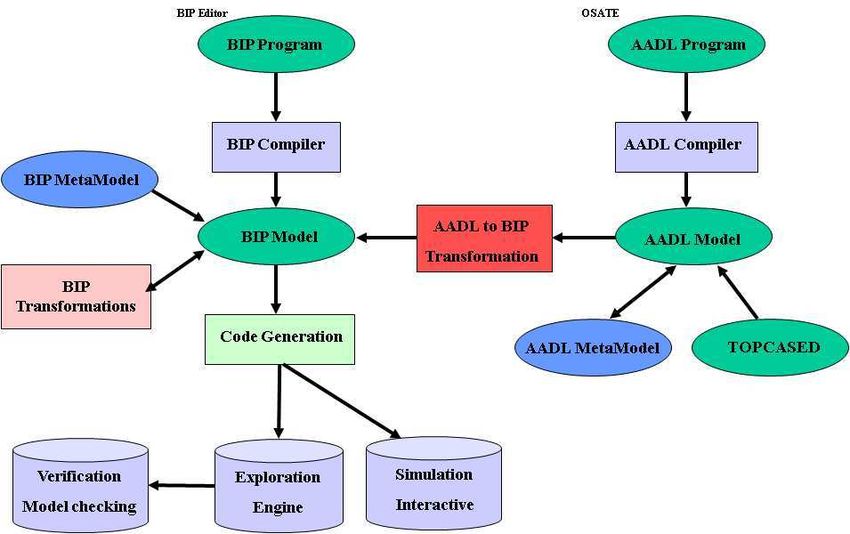
The tool chain is described in Figure 10, and it has the following features:
– AADL to BIP Transformation: Using model transformations, allows to per-
form analysis on the models before code generation. The tool generating BIP
from AADL (Figure 10) has been implemented in Java, as a set of plugins for
the open source Eclipse platform. It takes an input an AADL model(.aaxl)
conforming to the AADL metamodel and generates a BIP model conforming
to the BIP metamodel. Models generated may be timed or untimed. Timed
Toulouse, France, September 29, 2008 49MoDELS'08 ACES-MB Workshop Proceedings
models can be transformed into untimed models in which time progress is
represented by a tick port that exists in all timed components and a connec-
tor connecting all tick ports.
– Code Generation: Takes as input a BIP model and generate the C/C++
code to be executed by the Engine.
– Exploration Engine: The engine has a state space exploration mode, which
under some restrictions on the data used, generates state graphs that can be
analyzed by using finite state model-checking tools.
– Simulation: Monitors the state of atomic components and finds all the en-
abled interactions by evaluating the guards on the connectors. Then, between
the enabled interactions, priority rules are used to eliminate the ones with
low priority.
– Verification: Automatic verification is very useful for early error detection.
Fig. 10. AADL to BIP Tool Architecture
6 Case studies
We used some examples of AADL [3, 2] (with annex behavior specification) to
check the feasibility of our translation from AADL to BIP. In this section, we
present the example of a simplistic flight computer [2].
The Flight Computer has a thread called Sensor Sim that periodically sends
integers data for the current AoA(angle-of-attack) and Climb Rate, and an event
in case of Engine Failure. It also has a thread called Stall Monitor that is periodic
and monitors the condition of the AoA and Climb Rate sensors and raise a stall
warning if certain conditions are met. The thread Operator simulates the pilot. It
is a periodic thread that sends a command (Gear Cmd) at every dispatch to raise
Toulouse, France, September 29, 2008 50MoDELS'08 ACES-MB Workshop Proceedings
or lower the landing gear of the aircraft. The thread Landing Gear simulates the
landing gear subsystem. It receives a command to start a landing gear operation,
and is a sporadic thread with a minimum inter-arrival time of 3 seconds. The
thread HCI is a human computer interface. It receives a Stall Warning as an event
data of type Integer; Engine Failure as an event; a landing gear command from the
pilot. It may send a landing gear operation request (Gear Req) to the landing gear
subsystem, and receives a landing gear operation acknowledgement (Gear Ack)
from the landing gear subsystem. It is a sporadic thread with a minimum inter-
arrival time of 10ms. The graphical representation of Flight Computer system
model is given in Figure 11.
Fig. 11. Flight Computer Architecture
6.1 BIP model
The AADL model of the Flight Computer is transformed into BIP automatically
by using our AADL to BIP translation tool. Figure 12 shows the obtained BIP
model. This figure represents the BIP atomic components (AADL Threads) and
connectors between them. Notice that we omit here the connectors between
threads, process and scheduler that are shown in the Figure 9.
The component Dummy In Out models the communication between the Dummy Out
and Dummy In events ports. In the AADL model (Figure 11), these two events
are used to control thread reactivation: execution of the Landing Gear thread is
activated by the Dummy In event; it emits a Dummy Out event upon completion.
Thus, synchronizing these two events ensures periodic activation of this thread.
Toulouse, France, September 29, 2008 51MoDELS'08 ACES-MB Workshop Proceedings
Fig. 12. BIP model for the Flight computer (including observer property, dashed)
6.2 Verification
The model construction methodology applied to this example, opens the way for
enhanced analysis and early error detection by using verifications techniques.
Once the model has been generated, two model checking techniques for ver-
ification have been applied:
Model checking by Aldebaran: The first technique of verification is deadlock
detection by using the tool Aldebaran [12]. Exhaustive exploration by the BIP
exploration engine, generates a Labeled Transition System (LTS) which can be
analyzed by model checking. e.g, Aldebaran takes as input the LTS generated
from BIP and checks for deadlock-freedom. We have checked that the model is
deadlock-free.
Model checking with observers: The second technique of verification is by using
BIP observers to express and check requirements. Observers allow us to express
in a much simple manner most safety requirements. We apply this technique to
verify two properties:
• Verification of thread deadlines by using an observer component keeping
track of the execution time of threads. If the execution time of a thread
exceeds its deadline the observer moves to an error state.
• Verification of synchronization between components: Landing Gear is sporad-
ically activated bye HCI trough the Req port. When it is activated, it send
back an acknowledgement through the ACK port, and possibly reactivates
itself through the Dummy In Out component. This property can be verified
by an observer which monitors the interactions between HCI, landing Gear
and Dummy In Out components (Figure 11).
Toulouse, France, September 29, 2008 52MoDELS'08 ACES-MB Workshop Proceedings
7 Conclusion
The Architecture Analysis and Design Language (AADL) suffers from the ab-
sence of concrete operational semantics. In this paper, we address this problem by
providing a translation from AADL to BIP, which has an operational semantics
formally defined in terms of labelled transition systems. This translation allows
simulation of AADL models, as well as application verification techniques, such
as state exploration (using IF toolset [13]) or component-based deadlock detec-
tion (using Aldebaran [12], and D-Finder tool [11]). The proposed method has
been implemented in translation tool, which has been tested on the Flight Com-
puter case study, also presented in this paper. Future work includes incorporating
features that will appear in V2.0 of the AADL standard.
References
1. Annex behavior specification sae as5506.
2. http://aadl.enst.fr/arc/doc/.
3. http://gforge.enseeiht.fr/docman/?group id=37.
4. http://www-verimag.imag.fr/ async/bipmetamodel.php.
5. Sae. architecture analysis & design language (standard sae as5506), september
2004, available at http://www.sae.org.
6. Sei. open source aadl tool environment. http://la.sei.cmu.edu/aadlinfosite/ open-
sourceaadltoolenvironment.html.
7. Topcased. http://www.topcased.org/.
8. A. Basu, S. Bensalem, M. Gallien, F. Ingrand, C. Lesire, T.H. Nguyen, and
J. Sifakis. Incremental component-based construction and verification of a robotic
system. In Proceedings of ECAI’08, Patras, Greece, 2008.
9. A. Basu, M. Bozga, and J. Sifakis. Modeling heterogeneous real-time components
in bip. In Proceedings of SEFM ’06, Pune, India, pages 3–12. IEEE Computer
Society, 2006.
10. A. Basu, L. Mounier, M. Poulhiès, J. Pulou, and J. Sifakis. Using bip for modeling
and verification of networked systems – a case study on tinyos-based networks. In
Proceedings of NCA’07, Cambridge, MA USA, pages 257–260, 2007.
11. S. Bensalem, M. Bozga, J. Sifakis, and T.H. Nguyen. Compositional verification
for component-based systems and application. In Proceedings of ATVA’08, Seoul,
South Korea, 2008.
12. M. Bozga, J-C. Fernandez, A. Kerbrat, and L. Mounier. Protocol verification with
the aldebaran toolset. STTT, 1:166–183, 1997.
13. M. Bozga, S. Graf, Il. Ober, Iul. Ober, and J. Sifakis. The if toolset. In Proceedings
of SFM’04, Bertinoro, Italy, volume 3185 of LNCS, pages 237–267, September
2004.
14. J. Sifakis G. Gossler. Composition for component-based modeling. Science of
Computer Programming, 55:161–183, March 2005.
15. M. Poulhiès, J. Pulou, C. Rippert, and J. Sifakis. A methodology and support-
ing tools for the development of component-based embedded systems. In 13th
Monterey Workshop, Paris, France, volume 4888 of LNCS, pages 75–96, 2006.
Toulouse, France, September 29, 2008 53You can also read