Power Upgrading of Transmission Line by Combining AC-DC Transmission
←
→
Page content transcription
If your browser does not render page correctly, please read the page content below
P. Vijay Kumar Babu, P. Bhaskara Prasad, M.Padma Lalitha / International Journal of
       Engineering Research and Applications (IJERA) ISSN: 2248-9622 www.ijera.com
                   Vol. 2, Issue 6, November- December 2012, pp.1699-1704
  Power Upgrading of Transmission Line by Combining AC–DC
                        Transmission
      P. Vijay Kumar Babu*, P. Bhaskara Prasad ** , M.Padma Lalitha***
                  *(P.G Student, Department of Electrical Engg, AITS College, Rajampeta,)
              ** (Assistant professor, Department of Electrical Engg, AITS college, Rajampeta,)
                  *** (Professor, Department of Electrical Engg, AITS college, Rajampeta,)

ABSTRACT
         Long extra high voltage (EHV) ac lines          full utilization of existing transmission facilities
cannot be loaded to their thermal limits in order        without decreasing system availability and security.
to keep sufficient margin against transient              The flexible ac transmission system (FACTS)
instability. With the scheme proposed in this            concepts, based on applying state-of-the-art power
project, it is possible to load these lines very close   electronic technology to existing ac transmission
to their thermal limits. The conductors are              system, improve stability to achieve power
allowed to carry usual ac along with dc                  transmission close to its thermal limit. Another way
superimposed on it. The added dc power flow              to achieve the same goal is simultaneous ac–dc
does not cause any transient instability. This           power transmission in which the conductors are
project gives the feasibility of converting a            allowed to carry superimposed dc current along with
double circuit ac line into composite ac–dc power        ac current. Ac and dc power flow independently,
transmission line to get the advantages of parallel      and the added dc power flow does not cause any
ac–dc transmission to improve stability and              transient instability.
damping out oscillations. Simulation and                           Simultaneous ac–dc power transmission
experimental studies are carried out for the             was first proposed through a single circuit ac
coordinated control as well as independent               transmission line. In these proposals Mono-polar dc
control of ac and dc power transmissions. No             transmission with ground as return path was used.
alterations of conductors, insulator strings, and        There were certain limitations due to use of ground
towers of the original line are needed. Substantial      as return path. Moreover, the instantaneous value of
gain in the load ability of the line is obtained.        each conductor voltage with respect to ground
Master current controller senses ac current and          becomes higher by the amount of the dc voltage,
regulates the dc current orders for converters           and more discs are to be added in each insulator
online such that conductor current never exceeds         string to withstand this increased voltage. However,
its thermal limit.                                       there was no change in the conductor separation
                                                         distance, as the line-to-line voltage remains
Index Terms— Extra high voltage (EHV)                    unchanged. The feasibility study of conversion of a
transmission, flexible ac transmission system            double circuit ac line to composite ac–dc line
(FACTS), power system computer-aided design              without altering the original line conductors, tower
(PSCAD) simulation, simultaneous ac–dc power             structures, and insulator strings has been presented.
transmission.                                            In this scheme, the dc power flow is point-to- point
                                                         bipolar transmission system.
I. INTRODUCTION
          In Recent years, environmental, right-of-      II.SIMULTANEOUS               AC–DC POWER
way, and cost concerns have delayed the                  TRANSMISSION
construction of a new transmission line, while           A. Basic scheme for composite ac–dc
demand of electric power has shown steady but            transmission.
geographically uneven growth. The power is often                  The dc power is obtained through line
available at locations not close to the growing load     commutated 12-pulse rectifier bridge used in
centers but at remote locations. These locations are     conventional HVDC and injected to the neutral
largely determined by regulatory policies,               point of the zigzag connected secondary of sending
environmental acceptability, and the cost of             end transformer and is reconverted to ac again by
available energy. The wheeling of this available         the conventional line commutated 12-pulse bridge
energy through existing long ac lines to load centers    inverter at the receiving end. The inverter bridge is
has a certain upper limit due to stability               again connected to the neutral of zig-zag connected
considerations. Thus, these lines are not loaded to      winding of the receiving end transformer.
their thermal limit to keep sufficient margin against
transient instability. The present situation demands
the review of traditional power transmission theory
and practice, on the basis of new concepts that allow

                                                                                                  1|Page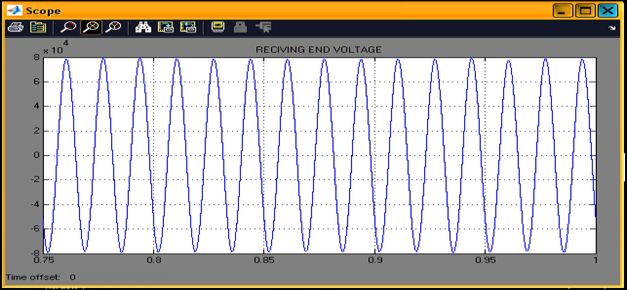
P. Vijay Kumar Babu, P. Bhaskara Prasad, M.Padma Lalitha / International Journal of
       Engineering Research and Applications (IJERA) ISSN: 2248-9622 www.ijera.com
                   Vol. 2, Issue 6, November- December 2012, pp.1699-1704
                                                          for active and reactive powers in terms of A, B, C,
                                                          and D parameters of each line may be written as
                                                                            ES=AER+BIR             (1)
                                                                                                       (2)
                                                                            IS=CER+DIR
                                                                                    *   *   2 *      (3)
                                                                  PS+JQS= - ES*ER/B +D ES /B
                                                                  PR+jQR= ES*ER/B*-A* ER2/B*.         (4)

    Fig. 1 depicts the basic scheme for simultaneous
ac–dc power flow through a double circuit ac
transmission line.
          The double circuit ac transmission line
carriers both three-phase ac and dc power. Each
conductor of each line carries one third of the total
dc current along with ac current. Resistance being
equal in all the three phases of secondary winding of
zig-zag transformer as well as the three conductors
of the line, the dc current is equally divided among
all the three phases. The three conductors of the
second line provide return path for the dc current.       III. DESCRIPTION OF THE SYSTEM
Zig-zag connected winding is used at both ends to         MODEL
avoid saturation of transformer due to dc current.        A. Description of the system model:
Two fluxes produced by the dc current Id/3 flowing                  A synchronous machine is feeding power
through each of a winding in each limb of the core        to infinite bus via a double circuit,three-
of a zig-zag transformer are equal in magnitude and       phase,400KV,50Hz, 450Km ac transmission line.
opposite in direction. So the net dc flux at any          The 2750MVA,24KV synchronous machine is
instant of time becomes zero in each limb of the          dynamically modeled, a field coil on d-axis and a
core. Thus, the dc saturation of the core is avoided.     damper coil on q-axis, by Park’s equations with the
A high value of reactor Xd is used to reduce              frame of reference based in rotor. It is equipped with
harmonics in dc current. In the absence of zero           an IEEE type AC4A excitation system of which
sequence and third harmonics or its multiple              block diagram is shown in Fig. 3. Transmission
harmonic voltages, under normal operating                 lines are represented as the Bergeron model. It is
conditions, the ac current flow through each              based on a distributed LC parameter traveling wave
transmission line will be restricted between the          line model, with lumped resistance. It represents the
zigzag connected windings and the three conductors        L and C elements of a PI section in a distributed
of the transmission line. Even the presence of these      manner (i.e., it does not use lumped parameters).
components of voltages may only be able to produce                  It is roughly equivalent to using an infinite
negligible current through the ground due to high         number of PI sections, except that the resistance is
value of Xd.                                              lumped (1/2 in the middle of the line, 1/4 at each
          Assuming the usual constant current             end). Like PI sections, the Bergeron model
control of rectifier and constant extinction angle        accurately represents the fundamental frequency
control of inverter, the equivalent circuit of the        only. It also represents impedances at other
scheme under normal steady-state operating                frequencies, except that the losses do not change.
condition is given in Fig. 2. The dotted lines in the     This model is suitable for studies where the
figure show the path of ac return current only. The       fundamental frequency load flow is most important.
second transmission line carries the return dc            The converters on each end of dc link are modeled
current, and each conductor of the line carries Id/3      as line commutated two six- pulse bridge (12-pulse),
along with the ac current per phase. And are the          Their control system consist of constant current
maximum values of rectifier and inverter side dc          (CC) and constant extinction angle (CEA) and
voltages and are parameters per phase of each line.       voltage dependent current order limiters (VDCOL)
Rcr, Rci are commutating resistances, and, α, γ are       control. The converters are connected to ac buses
firing and extinction angles of rectifier and inverter,   via Y-Y and Y- converter transformers. Each bridge
respectively. Neglecting the resistive drops in the       is a compact power system computer-aided design
line conductors and transformer windings due to dc        (SIMULINK) representation of a dc converter,
current, expressions for ac voltage and current, and      which includes a built in six-pulse Graetz converter
                                                          bridge (can be inverter or rectifier), an internal

                                                                                                1700 | P a g e
P. Vijay Kumar Babu, P. Bhaskara Prasad, M.Padma Lalitha / International Journal of
Engineering Research and Applications (IJERA) ISSN: 2248-9622 www.ijera.com
Vol. 2, Issue 6, November- December 2012, pp.1699-1704
phase locked oscillator (PLO), firing and valve A. Technology involved in an HVDC system:
blocking controls, and firing angle /extinction α There are three ways of achieving conversion
angle γ measurements. It also includes built in RC 1. Natural commutated converters
snubber circuits for each thyristor. The controls used 2. Capacitor Commutated Converters
in dc system are those of CIGRE Benchmark, 3. Forced Commutated Converters
modified to suit at desired dc voltage. Ac filters at
each end on ac sides of converter transformers are
connected to filter out 11th and 13th harmonics. 1. Natural commutated converter: (NCC):
These filters and shunt capacitor supply reactive NCC are most used in the HVDC systems
power requirements of converters. as of today. The component that enables this
A master current controller (MCC), shown conversion process is the thyristor, which is a
in Fig. 4, is used to control the current order for controllable semiconductor that can carry very high
converters. It measures the conductor ac current, currents (4000 A) and is able to block very high
computes the permissible dc current, and produces voltages (up to 10 kV). By means of connecting the
dc current order for inverters and rectifiers. thyristors in series it is possible to build up a
thyristor valve, which is able to operate at very high
voltages (several hundred of kV).The thyristor valve
is operated at net frequency (50 Hz or 60 Hz) and by
means of a control angle it is possible to change the
DC voltage level of the bridge.
2. Capacitor Commutated Converters (CCC):
An improvement in the thyristor-based
Commutation, the CCC concept is characterized by
the use of commutation capacitors inserted in series
between the converter transformers and the thyristor
valves. The commutation capacitors improve the
commutation failure performance of the converters
IV. HIGH VOLTAGE DC
when connected to weak networks.
TRANSMISSION
This chapter describes an overview of the
3. Forced Commutated Converters:
importance of the HVDC systems in the present
This type of converters introduces a
world. Then it discusses about the various
spectrum of advantages, e.g. feed of passive
parameters dealing with the HVDC systems. Over
networks (without generation), independent control
long distances bulk power transfer can be carried
of active and reactive power, power quality. The
out by a high voltage direct current (HVDC)
valves of these converters are built up it
connection cheaper than by a long distance AC
semiconductors with the ability not only to turn-on
transmission line. HVDC transmission can also be
but also to turn-off. They are known as Voltage
used where an AC transmission scheme could not
Source Converters (VSC). Two types of
(e.g. through very long cables or across borders
semiconductors are normally used in voltage source
where the two AC systems are not synchronized or
converters: the GTO (Gate Turn-Off Thyristor) or
operating at the same frequency). However, in order
the IGBT (Insulated Gate Bipolar Transistor). Both
to achieve these long distance transmission links,
of them have been in frequent use in industrial
power converter equipment is required, which is a
application, since the early eighties. The VSC
possible point of failure and any interruption in
commutates with high frequency (not with the net
delivered power can be costly. It is therefore of
frequency). The operation of the converter is
critical importance to design a HVDC scheme for a
achieved by Pulse Width Modulation (PWM).With
given availability. The HVDC technology is a high
PWM it is possible to create any phase angle or
power electronics technology used in electric power
amplitude (up to certain limit) by changing the
systems. It is an efficient and flexible method to
PWM pattern, which can be done almost
transmit large amounts of electric power over long
instantaneously. Thus, PWM offers the possibility to
distances by overhead transmission lines or
control both active and reactive power
underground/submarine cables. It can also be used
independently. This makes the PWM Voltage
to interconnect asynchronous power systems. The
Source Converter a close to ideal component in the
fundamental process that occurs in an HVDC
transmission network. From a transmission network
system is the conversion of electrical current from
viewpoint, it acts as a motor or generator without
AC to DC (rectifier) at the transmitting end and
mass that can control active and reactive power
from DC to AC (inverter) at the receiving end.
almost instantaneously.
1701 | P a g eP. Vijay Kumar Babu, P. Bhaskara Prasad, M.Padma Lalitha / International Journal of
Engineering Research and Applications (IJERA) ISSN: 2248-9622 www.ijera.com
Vol. 2, Issue 6, November- December 2012, pp.1699-1704
B. Configurations of HVDC: 4. Multi-terminal HVDC system:
There are different types of HVDC systems which
are
1. Mono-polar HVDC system:
In the mono-polar configuration, two
converters are connected by a single pole line and a
positive or a negative DC voltage is used. In Fig.
There is only one Insulated transmission conductor
installed and the ground or sea provides the path for
the return current.
In the multi terminal configuration, three or
more HVDC converter stations are geographically
2. Bipolar HVDC system:
separated and interconnected through transmission
This is the most commonly used
lines or cables. The System can be either parallel,
configuration of HVDC transmission systems. The
where all converter stations are connected to the
bipolar configuration, shown in Fig. Uses two
same voltage as shown in Fig(b). or series
insulated conductors as Positive and negative poles.
multiterminal system, where one or more converter
The two poles can be operated independently if both
stations are connected in series in one or both poles
Neutrals are grounded. The bipolar configuration
as shown in Fig. (c). A hybrid multiterminal system
increases the power transfer capacity. Under normal
contains a combination of parallel and series
operation, the currents flowing in both poles are
connections of converter stations.
identical and there is no ground current. In case of
failure of one pole power transmission can continue
C. DC transmission control:
in the other pole which increases the reliability.
The current flowing in the DC transmission
Most overhead line HVDC transmission systems use
line shown in Figure below is determined by the DC
the bipolar configuration.
voltage difference between station A and station B.
Using the notation shown in the figure, where rd
represents the total resistance of the line, we get for
the DC current
And the power transmitted into station B is
3. Homo-polar HVDC system:
In the homo polar configuration, shown in
Fig. Two or more conductors have the negative
polarity and can be operated with ground or a In rectifier operation the firing angle α
metallic return. With two Poles operated in parallel, should not be decreased below a certain minimum
the homo polar configuration reduces the insulation value αmin normally 3°-5° in order to make sure that
costs. However, the large earth return current is the there really is a positive voltage across the valve at
major disadvantage. the firing instant. In inverter operation the extinction
angle should never decrease below a certain
minimum value γmin, normally 17°-19° otherwise the
risk of commutation failures becomes too high. On
the other hand, both α and γ should be as low as
possible to keep the necessary nominal rating of the
equipment to a minimum. Low values of α and γ
also decrease the consumption of reactive power and
the harmonic distortion in the AC networks.
To achieve this, most HVDC systems are controlled
to maintain γ= γmin, in normal operation. The DC
1702 | P a g eP. Vijay Kumar Babu, P. Bhaskara Prasad, M.Padma Lalitha / International Journal of
Engineering Research and Applications (IJERA) ISSN: 2248-9622 www.ijera.com
Vol. 2, Issue 6, November- December 2012, pp.1699-1704
voltage level is controlled by the transformer tap these signals will influence the dynamics of the
changer in inverter station B. The DC current is total control system.
controlled by varying the DC voltage in rectifier
station A, and thereby the voltage difference V. SIMULATION RESULTS
between A and B. Due to the small DC resistances The performance of the proposed control
in such a system, only a small voltage difference is system was evaluated with a detailed simulation
required, and small variations in rectifier voltage model using the MATLAB/Simulink,
gives large variations in current and transmitted SimPowerSystems to represent the master control,
power. The DC current through a converter cannot transformers, sources and transmission lines, and
change the direction of flow. So the only way to Simulink blocks to simulate the control system.
change the direction of power flow through a DC
transmission line is to reverse the voltage of the line. Combined ac dc current and ac current in zigzag
But the sign of the voltage difference has to be kept transformer:-
constantly positive to keep the current flowing. To
keep the firing angle α as low as possible, the
transformer tap changer in rectifier station A is
operated to keep α on an operating value which
gives only the necessary margin to αmin to be able
to control the current.
D. Master control system:
The master control, however, is usually
system specific and individually designed.
Depending on the requirements of the transmission,
the control can be designed for constant current or
constant power transmitted, or it can be designed to
help stabilizing the frequency in one of the AC
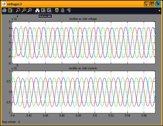
networks by varying the amount of active power Rectifier ac voltage and current:-
transmitted. The control systems are normally
identical in both converter systems in a
transmission, but the master control is only active in
the station selected to act as the master station,
which controls the current command. The calculated
current command is transmitted by a communication
system to the slave converter station, where the pre-
designed current margin is added if the slave is to
act as rectifier, subtracted if it is to act as inverter. In
order to synchronize the two converters and assure
that they operate with same current command, a
tele-communications channel is required.
Sending end voltage:-
Should the telecommunications system fail for
any reason, the current commands to both
converters are frozen, thus allowing the
transmission to stay in operation. The
requirements for the telecommunications system
are especially high if the transmission is required
to have a fast control of the transmitted power, Receiving end voltage:-
and the time delay in processing and transmitting
1703 | P a g eP. Vijay Kumar Babu, P. Bhaskara Prasad, M.Padma Lalitha / International Journal of
Engineering Research and Applications (IJERA) ISSN: 2248-9622 www.ijera.com
Vol. 2, Issue 6, November- December 2012, pp.1699-1704
[8] Padiyar, HVDC Power Transmission
System. New Delhi, India: Wiley Eastern,
1993.
[9] E. W. Kimbark, Direct Current
Transmission. New York: Wiley, 1971,
vol. I.
[10] J. Arillaga and N. R.Watson, Computer
Modelling of Electrical Power Systems.
Chichester, U.K.: Wiley, 2003.
VI. CONCLUSION
The feasibility to convert ac
transmission line to a composite ac–dc line has been
demonstrated. For the particular system studied,
there is substantial increase (about 83.45%) in the
load ability of the line. The line is loaded to its
thermal limit with the superimposed dc current. The
dc power flow does not impose any stability
problem. The advantage of parallel ac–dc
transmission is obtained. Dc current regulator may
modulate ac power flow. There is no need for any
modification in the size of conductors, insulator
strings, and towers structure of the original line. The
optimum values of ac and dc voltage components of
the converted composite line are 1/2 and 1/√2 times
the ac voltage before conversion, respectively.
REFERENCES
[1] L. K. Gyugyi, ―Unified power flow concept
for flexible A.C. transmission system,‖
Proc. Inst. Elect. Eng., p. 323, Jul. 1992.
[2] L. K. Gyugyi et al., ―The unified power
flow controller; a new approach to power
transmission control,‖ IEEE Trans. Power
Del., vol. 10, no. 2, pp. 1085–1097, Apr.
1995.
[3] N. G. Hingorani, ―FACTS—flexible A.C.
transmission system,‖ in Proc. Inst. Elect.
Eng. 5th. Int. Conf. A.C. D.C. Power
Transmission, London, U.K., 1991.
[4] P. S. Kundur, Power System Stability and
Control. New York: Mc- Graw-Hill, 1994.
[5] K. P. Basu and B. H. Khan, ―Simultaneous
ac-dc power transmission,‖ Inst. Eng.
(India) J.-EL, vol. 82, pp. 32–35, Jun.
2001.
[6] H. Rahman and B. H. Khan, ―Enhanced
power transfer by Simultaneous
transmission of AC-DC: a new FACTS
concept,‖ in Proc. Inst. Elect. Eng. Conf.
Power Electronics, Machines, Drives,
Edinburgh, U.K., Mar. 31– Apr. 2 2004,
vol. 1, pp. 186–191.
[7] A. Clerici, L. Paris, and P. Danfors,
―HVDC conversion of HVAC line to
provide substantial power upgrading,‖
IEEE Trans. Power Del., vol. 6, no. 1, pp.
324–333, Jan. 1991.
1704 | P a g eYou can also read