LTE Transmission Modes and Beamforming White Paper
←
→
Page content transcription
If your browser does not render page correctly, please read the page content below
LTE Transmission Modes and
Beamforming
White Paper

Multiple input multiple output (MIMO)
technology is an integral part of 3GPP
E-UTRA long term evolution (LTE). As
part of MIMO, beamforming is also used in
LTE.
This white paper discusses the basics of
beamforming and explains the eight MIMO
transmission modes in LTE Release 9.

                                                                     Bernhard Schulz
                                                          Octobber 2011 – 1MA186_0e
                                            White Paper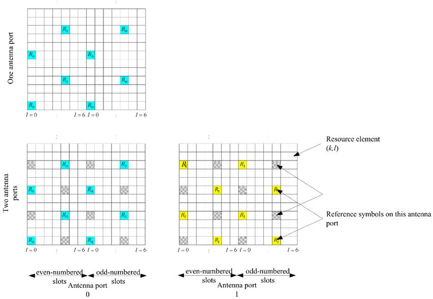
Table of Contents

            1       Introduction ............................................................................ 3

            2       MIMO and Beamforming Technologies ................................ 3
            2.1     MIMO..............................................................................................................3
            2.2     Beamforming basics ....................................................................................4
            2.3     Base Station Antennas ................................................................................8

            3       Transmission modes and Beamforming in LTE .................. 9
            3.1     Brief overview of LTE...................................................................................9
            3.1.1   Physical Channels and Signals ..................................................................9
            3.1.2   Downlink reference signal structure ........................................................10
            3.2     Transmission modes (TM) in LTE downlink ............................................11
            3.2.1   TM 1 – Single transmit antenna ................................................................12
            3.2.2   TM 2 – Transmit diversity ..........................................................................13
            3.2.3   TM 3 – Open loop spatial multiplexing with CDD....................................13
            3.2.4   TM 4 – Closed loop spatial multiplexing ..................................................14
            3.2.5   TM 5 – Multi-user MIMO .............................................................................14
            3.2.6   TM 6 – Closed loop spatial multiplexing using a single transmission
                    layer .............................................................................................................15
            3.2.7   TM 7 – Beamforming (antenna port 5)......................................................17
            3.2.8   TM 8 – Dual layer beamforming (antenna ports 7 and 8) .......................18
            3.3     Test requirements in 3GPP Release 9......................................................19
            3.3.1   Base station test.........................................................................................19
            3.3.2   UE test .........................................................................................................19
            3.4     Summary .....................................................................................................19

            4       Appendix............................................................................... 20
            4.1     Literature .....................................................................................................20
            4.2     Additional information ...............................................................................20

1MA186_0e                                                                                 Rohde & Schwarz LTE Beamforming 2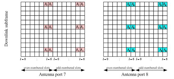
Introduction

                                                                                                  MIMO

            1 Introduction
              Modern communications networks use MIMO technology to achieve high data rates.
              As a special MIMO technique, beamforming also permits targeted illumination of
              specific areas, making it possible to improve transmission to users at the far reaches of
                                                                                                TM
              cell coverage. Like other communications standards such as WLAN and WiMAX ,
              LTE also defines beamforming. Beamforming is particularly important for the time
              division duplex (TDD) mode in LTE. This white paper describes the eight available
              MIMO transmission modes in LTE as specified in 3GPP Release 9, as well as how
              beamforming is used in LTE.

            2 MIMO and Beamforming Technologies

            2.1 MIMO
              This paper discusses the MIMO concepts only to the extent that they apply to LTE
              transmission modes (see 3.2). Refer to [3] for a more detailed description of the MIMO
              concept as well as for a look at how MIMO is used in various communications systems.

              MIMO systems are used to improve the robustness of data transmission or to increase
              data rates. Typically, a MIMO system consists of m transmit antennas and n receive
              antennas (Figure 1).

              Figure 1: MIMO system with m TX and n RX antennas

1MA186_0e                                                             Rohde & Schwarz LTE Beamforming 3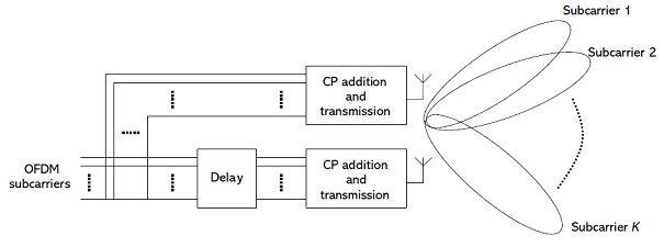
MIMO and Beamforming Technologies

                                                                                          Beamforming basics

              Simply stated, the receiver receives the signal y that results when the input signal
              vector x is multiplied by the transmission matrix H.

              y=H*x

              Transmission matrix H contains the channel impulse responses hnm, which reference
              the channel between the transmit antenna m and the receive antenna n.
              Many MIMO algorithms are based on the analysis of transmission matrix H
              characteristics. The rank (of the channel matrix) defines the number of linearly
              independent rows or columns in H. It indicates how many independent data streams
              (layers) can be transmitted simultaneously.

              >     Increasing the robustness of data transmission – transmit diversity

                  When the same data is transmitted redundantly over more than one transmit
                  antenna, this is called TX diversity. This increases the signal-to-noise ratio. Space-
                  time codes are used to generate a redundant signal. Alamouti developed the first
                  codes for two antennas. Today, different codes are available for more than two
                  antennas.

              >     Increasing the data rate – spatial multiplexing

                  Spatial multiplexing increases the data rate. Data is divided into separate streams,
                  which are then transmitted simultaneously over the same air interface resources.
                  The transmission includes special sections (also called pilots or reference signals)
                  that are also known to the receiver. The receiver can perform a channel estimation
                  for each transmit antenna’s signal. In the closed-loop method, the receiver reports
                  the channel status to the transmitter via a special feedback channel. This enables
                  fast reactions to changing channel circumstances, e.g. adaptation of the number of
                  multiplexed streams.

                  When the data rate is to be increased for a single user equipment (UE), this is called
                  Single User MIMO (SU-MIMO). When the individual streams are assigned to various
                  users, this is called Multi User MIMO (MU-MIMO)

            2.2 Beamforming basics
              Beamforming uses multiple antennas to control the direction of a wavefront by
              appropriately weighting the magnitude and phase of individual antenna signals
              (transmit beamforming). For example this makes it possible to provide better coverage
              to specific areas along the edges of cells. Because every single antenna in the array
              makes a contribution to the steered signal, an array gain (also called beamforming
              gain) is achieved.

1MA186_0e                                                                Rohde & Schwarz LTE Beamforming 4
MIMO and Beamforming Technologies
Beamforming basics
Receive beamforming makes it possible to determine the direction that the wavefront
will arrive (direction of arrival, or DoA). It is also possible to suppress selected
interfering signals by applying a beam pattern null in the direction of the interfering
signal.
Adaptive beamforming refers to the technique of continually applying beamforming to a
moving receiver. This requires rapid signal processing and powerful algorithms.
Figure 2: Antenna array with a distance d between the individual antennas. The additional path that a
wavefront must traverse between two antennas is d * sin $.
As seen in Figure 2, the wavefront of a signal must traverse the additional distance
d * sin < to the next antenna. Using the speed of light c, it is possible to calculate the
delay between the antennas.
(i 1)d sin
i = = (i 1)
c
d sin
=
c
The signal si at each antenna is:
This approximation is valid only for narrowband signals.
1MA186_0e Rohde & Schwarz LTE Beamforming 5MIMO and Beamforming Technologies
Beamforming basics
Written as a vector:
1
j
e
j2
e
s(t) = j3
·s(t) = a( )·s(t),
e
M
j ( M 1)
e
where a is the array steering vector.
Figure 3 shows an example of the amplitude response of an antenna array with eight
elements (uniform linear array, ULA) versus the angle . In this example, the maximum
is obtained when a signal coming from the boresight direction ( = 0) impinges on the
array.
Figure 3: Beampattern example of an 8-element ULA
Beamforming is made possible by weighting the magnitude and/or phase of the signal
at the individual antennas:
H
y(t) = w · a( ) · s(t),
where w is the weight vector. The signals are weighted so that they can be added
constructively in the direction of an intended transmitter/receiver, and destructively in
the direction of interferers.
1MA186_0e Rohde & Schwarz LTE Beamforming 6MIMO and Beamforming Technologies
Beamforming basics
Because beamforming is intended to provide the best signal possible to a UE at a
specific location, finding the weight vector w is an essential step. Two basic methods
for finding the weight vector can be used which also affects the arrangement of the
antenna array. The distance d between the antennas is a critical factor as well.
Determining the weighting using DoA
If the position of the UE is known, the beamforming weightings can be adapted
accordingly to optimize transmission for this UE. Therefore, specialized algorithms,
such as MUSIC [4] or ESPRIT [5]), could be used in the base station to determine the
DoA for the UE signal, and thus to determine its location. A uniform linear array (ULA)
antenna array is typically used, where the distance d between the individual antennas
is the same and d = >/2. This type of array can be seen as a spatial filtering and
sampling in the signal space. Just as the Nyquist criterion applies to sampling a signal
over time, the distance here must be d I J/2 in order to determine the DoA.
Determining the weighting using channel estimation
Other algorithms determine the optimum beamforming weighting from a channel
estimation; for example, by using existing training sequences. In a TDD system, uplink
and downlink are on the same frequency and thus the channel characteristics are the
same. That is why a feedback is not needed from the UE when a suitable uplink signal
is present that the base station can use to estimate the channel. In the case of TD-
LTE, the uplink sounding reference signal can be used.
Figure 4 shows how the distance between the antenna elements affects the antenna
characteristics, based on a simple example of a two-element array. With increasing
distance between the antenna elements, the side lobes are increasing.
Figure 4: The antenna diagram is affected by the distance d between the antennas. In this example, d
is 10 %, 30 %, and 50 % greater than 1/2. (CBI 0 refers to code book index 0, see chapter 3.2.4)
1MA186_0e Rohde & Schwarz LTE Beamforming 7MIMO and Beamforming Technologies
Base Station Antennas
2.3 Base Station Antennas
As described in the above section, the geometric characteristics of the antenna array
significantly affect the radiation characteristics. This is discussed here using the
example of conventional base station antennas.
At present, conventional passive base station antennas are typically made up of
multiple cross-polarized elements. In the y-axis, multiple elements are combined in
order to set the illumination (cell radius). All elements that have the same polarity
radiate the same signal (shown in color at the left antenna of Figure 5). Especially
relevant for MIMO and beamforming is the arrangement of the cross-polarized
elements and the columns in the x-axis.
The antenna at the left consists of two elements arranged at 90° to each other (cross-
polarized). Each "polarization column" (blue or red) represents an antenna element
that can transmit a different signal. This makes it possible to transmit two signals with a
compact antenna arrangement, such as for 2x2 MIMO or TX diversity. Analogously,
the antenna at the middle can radiate four independent signals (4xN MIMO), while the
antenna at the right can radiate eight independent signals (8xN MIMO).
The antennas shown in Figure 5 could also be used for beamforming. However,
beamforming requires correlated channels; that is, elements with the same polarization
(+45° or –45°) must be used. Also the distance between the columns should not be too
large. Beamforming could be carried out with two antenna elements (columns with the
same polarization) in the antenna layout in the middle, or with four antenna elements in
the layout on the right.
Base station antenna architectures are currently evolving. Active antennas are an
important trend that allow seamless integration of beamforming concepts, e.g. by
implementing dedicated transceivers for the required number of antenna elements.
Figure 5: Various cross-polarized base station antenna arrays for MIMO and beamforming.
1MA186_0e Rohde & Schwarz LTE Beamforming 8Transmission modes and Beamforming in LTE
Brief overview of LTE
3 Transmission modes and Beamforming in
LTE
3.1 Brief overview of LTE
A complete description of LTE is found in [2]. This white paper provides just a brief
overview.
3.1.1 Physical Channels and Signals
LTE defines a number of channels in the downlink as well as the uplink. Table 1 and
Table 2 provide an overview.
Downlink
LTE downlink physical channels
Name Purpose Comment
PDSCH Physical downlink shared channel user data
PDCCH Physical downlink control channel control information
PCFICH Physical control format indicator channel indicates format of PDCCH
PHICH Physical hybrid ARQ indicator channel ACK/NACK for uplink data
PBCH Physical broadcast channel information during cell search
LTE downlink physical signals
Primary and secondary synchronization signal information during cell search
RS Reference signals enables channel estimation
Table 1: Overview of LTE downlink physical channels and signals
Uplink
LTE uplink physical channels
Name Purpose Comment
PUSCH Physical downlink shared channel user data
PUCCH Physical uplink control channel control information
PRACH Physical random access channel preamble transmission
LTE uplink physical signals
DRS Demodulation reference signal channel estimation and demodulation
SRS Sounding reference signal uplink channel quality evaluation
1MA186_0e Rohde & Schwarz LTE Beamforming 9Transmission modes and Beamforming in LTE
Brief overview of LTE
Table 2: Overview of LTE uplink physical channels and signals
3.1.2 Downlink reference signal structure
The downlink reference signal structure is important for channel estimation. It defines
the principle signal structure for 1-antenna, 2-antenna, and 4-antenna transmission.
Specific pre-defined resource elements (indicated by R0-3) in the time-frequency
domain carry the cell-specific reference signal sequence. One resource element
represents the combination of one OFDM symbol in the time domain and one
subcarrier in the frequency domain. Figure 6 shows the principle of the downlink
reference signal structure for 1 antenna and 2 antenna transmission.
Figure 6: Distribution of the downlink reference signals in LTE; see top for one antenna and bottom
for two antennas. [1]
A different pattern is used for beamforming (see section 3.2.7). UE-specific reference
signals are used here. These are needed because whenever beamforming is used, the
physical downlink shared channel for each UE is sent with a different beamforming
weighting. The UE-specific reference signals and the data on the PDSCH for a UE are
transmitted with the same beamforming weighting.
1MA186_0e Rohde & Schwarz LTE Beamforming 10Transmission modes and Beamforming in LTE
Transmission modes (TM) in LTE downlink
LTE TDD UEs must (mandatory) support UE-specific reference signals, while it is
optional for LTE FDD UEs. Beamforming is of particular interest for LTE TDD because
the same frequency is used in the downlink and uplink.
Figure 7: Distribution of reference signals for transmission mode 7
In TM 8 also UE-specific reference signals (RS) are used. Since the same elements
are used for both streams, the reference signals must be coded differently so that the
UE can distinguish among them. Figure 14 in section 3.2.8 shows the position of the
RS in TM8.
3.2 Transmission modes (TM) in LTE downlink
In the downlink, LTE uses technologies such as MIMO to achieve high data rates;
however, it also offers fallback technologies such as transmit diversity or SISO. In the
Release 9 specification [1], up to four antennas are defined in the base station and up
to four antennas in the UE.
Beamforming is also supported. However, in this case the number of base station
antennas is not specified; it depends on the implementation. Arrangements with eight
antenna elements are realistic for ensuring sufficient beamforming gain.
To keep the UE complexity low, Releases 8/9 still do not specify a true MIMO in the
uplink for LTE (this will change with LTE Advanced). Receive beamforming in the
uplink can be carried out dependent on the base station implementation, however it
does not yet need to be standardized.
1MA186_0e Rohde & Schwarz LTE Beamforming 11Transmission modes and Beamforming in LTE
Transmission modes (TM) in LTE downlink
Figure 8: Block diagram of LTE transmission. One or two code words are mapped to one to four
layers. The layers are then applied to one to four antenna ports.
The various scenarios for the downlink are reflected in the different transmission
modes (TMs). Release 9 describes eight different TMs, which are explained below.
See Table 3: Overview of the eight transmission modes in LTE Release for an
overview.
Transmission modes in LTE Release 9
Transmission modes Description Comment
1 Single transmit antenna single antenna port; port 0
2 Transmit diversity 2 or 4 antennas
Open loop spatial multiplexing with cyclic
3 2 or 4 antennas
delay diversity (CDD)
4 Closed loop spatial multiplexing 2 or 4 antennas
5 Multi-user MIMO 2 or 4 antennas
Closed loop spatial multiplexing using a 1 layer (rank 1),
6
single transmission layer 2 or 4 antennas
single antenna port, port 5 (virtual
antenna port, actual antenna
7 Beamforming
configuration depends on
implementation)
dual-layer transmission,
8 Dual-layer beamforming
antenna ports 7 and 8
Table 3: Overview of the eight transmission modes in LTE Release 9.
3.2.1 TM 1 – Single transmit antenna
This mode uses only one transmit antenna.
1MA186_0e Rohde & Schwarz LTE Beamforming 12Transmission modes and Beamforming in LTE
Transmission modes (TM) in LTE downlink
3.2.2 TM 2 – Transmit diversity
Transmit diversity is the default MIMO mode. It sends the same information via various
antennas, whereby each antenna stream uses different coding and different frequency
resources. This improves the signal-to-noise ratio and makes transmission more
robust.
In LTE, transmit diversity is used as a fallback option for some transmission modes,
such as when spatial multiplexing (SM) cannot be used. Control channels, such as
PBCH and PDCCH, are also transmitted using transmit diversity.
For two antennas, a frequency-based version of the Alamouti codes (space frequency
block code, SFBC) is used, while for four antennas, a combination of SFBC and
frequency switched transmit diversity (FSTD) is used.
3.2.3 TM 3 – Open loop spatial multiplexing with CDD
This mode supports spatial multiplexing of two to four layers that are multiplexed to two
to four antennas, respectively, in order to achieve higher data rates. It requires less UE
feedback regarding the channel situation (no precoding matrix indicator is included),
and is used when channel information is missing or when the channel rapidly changes,
e.g. for UEs moving with high velocity.
In addition to the precoding as defined in Table 4, the signal is supplied to every
antenna with a specific delay (cyclic delay diversity, or CDD), thus artificially creating
frequency diversity.
Figure 9: TM 3: Spatial multiplexing with CDD; the individual subcarriers are delayed artificially.
Figure 9 shows the CDD principle. For two transmit antennas, a fixed precoding
(codebook index 0 is used as defined in Table 4), while for four antennas, the
precoders are cyclically switched.
1MA186_0e Rohde & Schwarz LTE Beamforming 13Transmission modes and Beamforming in LTE
Transmission modes (TM) in LTE downlink
3.2.4 TM 4 – Closed loop spatial multiplexing
This mode supports spatial multiplexing with up to four layers that are multiplexed to up
to four antennas, respectively, in order to achieve higher data rates. To permit channel
estimation at the receiver, the base station transmits cell-specific reference signals
(RS), distributed over various resource elements (RE) and over various timeslots. The
UE sends a response regarding the channel situation, which includes information
about which precoding is preferred from the defined codebook. This is accomplished
using an index (precoding matrix indicators, or PMI) defined in the codebook, a table
with possible precoding matrices that is known to both sides.
Spatial multiplexing LTE
Codebook Number of layers
index
1 2
1 1 1 1 0
0
2 1 2 0 1
1 1 1 1 1
1
2 1 2 1 1
1 1 1 1 1
2
2 j 2 j j
1 1
3 -
2 j
Table 4: Codebook indices for spatial multiplexing with two antennas, green background for two
layers; yellow background for one layer or TM 6 [1]
A corresponding table for four antennas (and correspondingly with up to four layers) is
also defined and is available in [1].
3.2.5 TM 5 – Multi-user MIMO
Mode 5 is similar to mode 4. It uses codebook-based closed loop spatial multiplexing,
however one layer is dedicated for one UE.
Figure 10: TM 5: Multi-user MIMO; the two data streams are divided between two UEs.
1MA186_0e Rohde & Schwarz LTE Beamforming 14Transmission modes and Beamforming in LTE
Transmission modes (TM) in LTE downlink
3.2.6 TM 6 – Closed loop spatial multiplexing using a single
transmission layer
This mode is a special type of closed loop spatial multiplexing (TM 4). In contrast to
TM 4, only one layer is used (corresponding to a rank of 1). The UE estimates the
channel and sends the index of the most suitable precoding matrix back to the base
station. The base station sends the precoded signal via all antenna ports. The
codebooks from Table 4 are used, but only the 1-layer variants (yellow background).
Weights for 1 Layer
Codebook
Matrix Weights Phase
index
1 1
0 0°
2 1
1 1
1 180°
2 1
1 1
2 90°
2 j
1 1
3 270°
2 j
Table 5: Precoding/weighting for a 1-layer scenario using the codebook index (the phase column
indicates the phase difference between the two antenna signals)
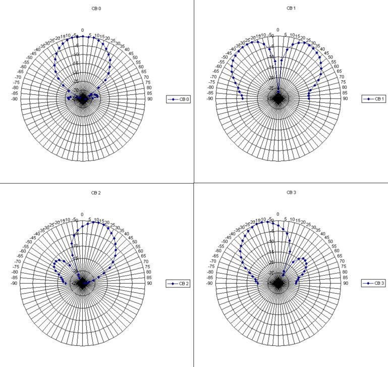
The precoding in the baseband of the signals to the different antennas results in a
beamforming effect (see Figure 11 for two antennas). With four transmit antennas
there are 16 different beamforming diagrams. This “implicit” beamforming effect is to
be distinguished from classical beamforming used in transmission modes 7 and 8, that
are aiming at achieving a direct impact on the antenna diagram, e.g. for illuminating
particular areas of a cell.
1MA186_0e Rohde & Schwarz LTE Beamforming 15Transmission modes and Beamforming in LTE
Transmission modes (TM) in LTE downlink
Figure 11: Schematic representation of TM 6 implicit beamforming for two antennas, codebook index
0…3
Figure 12: Block diagram for TM 6
Figure 12 shows the fundamental configuration.
1MA186_0e Rohde & Schwarz LTE Beamforming 16Transmission modes and Beamforming in LTE
Transmission modes (TM) in LTE downlink
3.2.7 TM 7 – Beamforming (antenna port 5)
This mode uses UE-specific reference signals (RS). Both the data and the RS are
transmitted using the same antenna weightings. Because the UE requires only the UE-
specific RS for demodulation of the PDSCH, the data transmission for the UE appears
to have been received from only one transmit antenna, and the UE does not see the
actual number of transmit antennas. Therefore, this transmission mode is also called
"single antenna port; port 5". The transmission appears to be transmitted from a single
"virtual" antenna port 5.
Figure 13: Beamforming in TM 7; use of UE-specific RS; the common channels use transmit diversity
There are different algorithms for calculating the optimum beamforming weightings. For
example, it is possible to determine the direction of the received uplink signal (DoA or
angle of arrival (AoA)), and from that calculate the beamforming weightings. However,
this requires an antenna array with a distance between the individual antenna
elements of d = >/2. It can be difficult to determine the DoA if the angular spread is not
small or if there is no dominant direction in the DoA.
Alternatively, it is possible to determine the optimum beamforming weighting from the
channel estimation. Because the uplink and downlink take place on the same
frequency in a TD-LTE system, the uplink sounding reference signals can be used
directly to estimate the channel, which can then be used to derive the weighting for the
downlink beamforming. In this case, the beamforming vector is determined by channel
estimation, and not from the DoA calculation.
The beamforming calculation is based on the uplink measurement, making calibration
of the antenna array and of the RF frontend a major factor in the accuracy of the
beamforming.
LTE does not specify any methods for determining the beamforming parameters. Other
methods, such as beamswitching, are also possible. Also the number of antennas and
the antenna architecture are left up to implementation.
1MA186_0e Rohde & Schwarz LTE Beamforming 17Transmission modes and Beamforming in LTE
Transmission modes (TM) in LTE downlink
3.2.8 TM 8 – Dual layer beamforming (antenna ports 7 and 8)
Specification of beamforming in LTE continues. While Release 8 of the LTE
specification defines beamforming with one layer (as described in the above section),
Release 9 specifies dual-layer beamforming. This will permit the base station to weight
two layers individually at the antennas so that beamforming can be combined with
spatial multiplexing for one or more UEs.
As in TM 7, UE-specific reference signals (RS) are also used here. Since, as can be
seen in Figure 14, the same elements are used, the reference signals must be coded
differently so that the UE can distinguish among them.
Figure 14: Distribution of reference signals for transmission mode 8 (antenna ports 7 and 8 ) [1]
Because two layers are used, both layers can be assigned to one UE (single-user
MIMO, Figure 15), or the two layers can be assigned to two separate UEs (multi-user
MIMO, Figure 16).
Figure 15: Dual-layer beamforming with SU-MIMO: Both beamformed data streams benefit the same
UE.
Figure 16: Dual-layer beamforming with MU-MIMO: The individual beamformed data streams each
benefit a different UE.
1MA186_0e Rohde & Schwarz LTE Beamforming 18Transmission modes and Beamforming in LTE
Test requirements in 3GPP Release 9
3.3 Test requirements in 3GPP Release 9
3GPP conformance test specifications for UEs contain a lot of tests with regards to
verification of functionality and performance of the different MIMO modes. However,
only few tests address beamforming with transmission modes 7 and 8. This is even
more true for the base station side. Because many beamforming parameters and
algorithms are not specified in LTE, there are only a limited number of prescribed tests
that directly affect beamforming. Additional tests, such as phase measurements, are
described in [6].
3.3.1 Base station test
No special beamforming measurements are specified for the transmitter or receiver
tests at the base station. Section 6.5.3 [7] of 36.141 (Base Station Conformance Tests)
specifies only the time offset between the up to four antenna ports for the transmitter.
3.3.2 UE test
For the UE receiver, several performance (TS 36.521-1, Section 8 [8]) tests are
specified under MIMO configurations.
A couple of tests apply for TDD mode with user-specific RS, thus Beamforming TMs 7
and 8 ( Section 8.3 with B.4, [8]); however, discrete beamforming settings with
precodings CB0….CB3 randomly selected from codebook table (Table 4) are used.
The UE must achieve a minimum throughput under fading conditions.
3.4 Summary
LTE Release 8 defines seven different transmission modes. Release 9 adds TM 8,
dual-layer beamforming. TMs 7 and 8 use "classical" beamforming with one or two
layers using UE-specific reference signals. These modes require a special antenna
array with a distance of d I /2. Feedback from the UE is not necessary. Different
algorithms are available for determining the optimum weighting. Beamforming for TD-
LTE is especially attractive because the same frequency is used in both the uplink and
the downlink so that the channel reciprocity can be exploited.
1MA186_0e Rohde & Schwarz LTE Beamforming 19Appendix
Literature
4 Appendix
4.1 Literature
[1] Technical Specification Group Radio Access Network; Physical Channels and
Modulation, Release 9; 3GPP TS 36.211 V 9.1.0, March 2010
[2] Rohde & Schwarz: UMTS Long Term Evolution (LTE) Technology Introduction,
Application Note 1MA111, September 2008
[3] Rohde & Schwarz: Introduction to MIMO, Application Note 1MA142, July 2009
[4] R. O. Schmidt, Multiple emitter location and signal parameter estimation,
in Proc. RADC Spectral Estimation Workshop, Rome, NY, 1979, pp. 243–258.
[5] A. Paulraj, R. Roy, and T. Kailath, A subspace rotation approach to signal
parameter estimation, Proc. IEEE, vol. 74, pp. 1044–1046, Jul. 1986.
[6] Rohde & Schwarz: LTE Beamforming Measurements, Application Note 1MA187,
September 2011
[7] Technical Specification Group Radio Access Network; Base Station Conformance
Testing, Release 9; 3GPP TS 36.141 V 9.6.0, December 2010
[8] Technical Specification Group Radio Access Network; UE conformance
specification, Release 9; 3GPP TS 36.521-1 V 9.3.0, December 2010
4.2 Additional information
Please send your comments and suggestions regarding this white paper to
TM-Applications@rohde-schwarz.com
1MA186_0e Rohde & Schwarz LTE Beamforming 20About Rohde & Schwarz
Rohde & Schwarz is an independent group
of companies specializing in electronics. It is
a leading supplier of solutions in the fields of
test and measurement, broadcasting,
radiomonitoring and radiolocation, as well as
secure communications. Established more
than 75 years ago, Rohde & Schwarz has
a global presence and a dedicated service
network in over 70 countries. Company
headquarters are in Munich, Germany.
Environmental commitment
> Energy-efficient products
> Continuous improvement in
environmental sustainability
> ISO 14001-certified environmental
management system
Regional contact
Europe, Africa, Middle East
+49 89 4129 123 45
customersupport@rohde-schwarz.com
North America
1-888-TEST-RSA (1-888-837-8772)
customer.support@rsa.rohde-schwarz.com
Latin America
+1-410-910-7988
customersupport.la@rohde-schwarz.com
Asia/Pacific
+65 65 13 04 88
customersupport.asia@rohde-schwarz.com
This application note and the supplied
programs may only be used subject to the
conditions of use set forth in the download
area of the Rohde & Schwarz website.
R&S® is a registered trademark of Rohde & Schwarz
GmbH & Co. KG. Trade names are trademarks of the
owners.
Rohde & Schwarz GmbH & Co. KG
Mühldorfstraße 15 | D - 81671 München
Phone + 49 89 4129 - 0 | Fax + 49 89 4129 – 13777
www.rohde-schwarz.comYou can also read