Design and analysis for interferometric measurements of the GMT primary mirror segments
←
→
Page content transcription
If your browser does not render page correctly, please read the page content below
Design and analysis for interferometric measurements of the
                      GMT primary mirror segments
                        J. H. Burgea,b, L. B. Kota, H. M. Martina, R. Zehnderb, C. Zhaob
                    a
                     Steward Observatory, University of Arizona, Tucson, AZ 85721, USA
              b
                  College of Optical Sciences, University of Arizona, Tucson, AZ 85721, USA

                                                        ABSTRACT
    The Giant Magellan Telescope (GMT) uses seven 8.4-m diameter segments to create a giant primary mirror,
    25 meters across with focal ratio f /0.7. The off-axis segments will be difficult to measure accurately, as they
    have 14.5 mm departure from the nearest fitting sphere! The test configuration adopted uses a large 3.75-m
    powered mirror to fold the light path and provide most of the aspheric correction, with a smaller mirror and
    computer generated hologram (CGH) providing the additional correction. These optics will be aligned to a
    vibration-insensitive interferometer using a combination of optical references created by the CGH and
    metrology with a laser tracker. Some key challenges for this system are presented here including, the system
    alignment, the large fold mirror, and the mechanical structure. Analysis of the optical test shows that it will
    meet GMT specifications, including the difficult requirement that the separate segments have matching radius
    of curvature. Additional corroborative testing will be performed to assure that the mirror segments are correctly
    figured.

    Keywords: telescopes, optical fabrication, optical testing, aspheres

                                                   1. INTRODUCTION
         The GMT uses a close packed array of seven 8.4-m segments to create the 25-m f/0.7 primary mirror.1 This
steep focal ratio minimizes the length of the telescope, but it drives the aspheric departure to be quite large. The
telescope and a plot of the 14.5-mm aspheric departure for one of the segments are shown in Figure 1. This aspheric
departure is compensated using mirrors and a computer generated hologram to allow an interferometric surface
measurement.

                                                                           Aspheric departure – 14.5 mm

                                                                                                                            mm
                                                                                                                       '0

Figure 1. The 25-m f /0.7 GMT primary mirror is made of 8.4-m diameter segments. The off-axis segments have 14.5 mm departure
from the best fitting sphere.

              Optomechanical Technologies for Astronomy, edited by Eli Atad-Ettedgui, Joseph Antebi, Dietrich Lemke,
                     Proc. of SPIE Vol. 6273, 62730M, (2006) · 0277-786X/06/$15 · doi: 10.1117/12.672484

                                                Proc. of SPIE Vol. 6273 62730M-1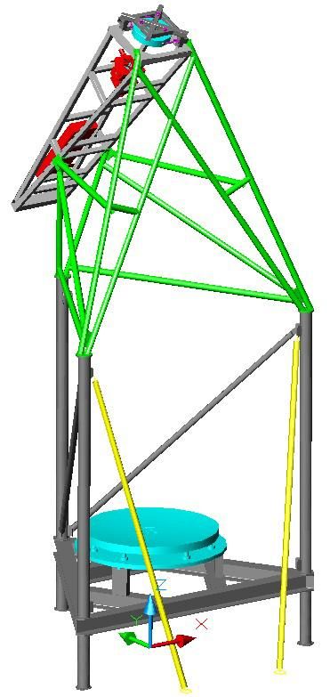
1.1 Requirements for optical testing
        The requirements for the optical measurements are derived from the telescope system specifications. These
flow down as contributions to budgets for wavefront, support force, or geometric tolerances, as shown in Table 1.
          Fabrication errors in primary mirrors are allowed to contribute a structure function that corresponds to
atmospheric seeing with 80% encircled energy T80 of 0.166 arcsec, with a goal of achieving images with T80 of
0.054 arcsec.2 Since the mirrors will be polished based on data from the interferometric test, we assume that errors in the
optical test contribute directly to errors in the mirror surface. We have allocated a goal for optical testing errors that has
a structure function 60% as large as the specification for the surface.
                                                                                 1000
         Our experience with large primaries indicates that we                                      astigmatism & spherical removed
will meet the requirement with significant margin over spatial                                      Low order aberrations removed
                                                                           rms                       GMT specification
scales less the 3 cm, where the polishing tools achieve excellent          wavefront
smoothing, and scales greater than 20 cm where the errors are              difference
easily addressed in polishing. This is easily seen in Figure 2             (nm)
                                                                                  100
showing the GMT goal with the structure function data from
LBT.
         The active support for the primary mirrors, which uses
165 force actuators to control the mirror bending, is capable of
large amplitude correction for the very lowest bending modes.                      10
Thus low-order shape errors due to either polishing or metrology                        0.01              0.1               1
                                                                                                                separation (m)
                                                                                                                                          10
will be corrected in the telescope with the support. We allow 50
N rms actuator force variation to accommodate mirror errors,               Figure 2. Structure function requirement for GMT, shown
out of an average force of 1070 N per actuator at zenith.                  with data from a completed 8.4-m LBT primary mirror

          Additional specification include tight tolerances on off-
axis distance and clocking angle (rotation of the segment about its mechanical axis) in order to limit displacements of the
segments relative to their cells, which are fixed in the telescope. There is also a tight requirement for matching radius of
curvature among all seven segments. The segments’ radii must be fabricated well enough in the lab that they can be
adjusted in the telescope using the active support to give essentially a perfect match in the telescope. The force required
to make this adjustment contributes to the 50 N rms budget.
Table 1. Error budget for GMT primary mirror segments, including allocation for optical test
                 Parameter                                          Primary mirror                                        Optical Test
                                                           Specification                          Goal                     Allocation
             Radius of curvature R                     36,000.0 + 1.0 mm                        + 0.3 mm                   + 0.3 mm
               Conic constant k                             -0.998286
                 Clear aperture                              8.365 m
               Off-axis distance                           8710 + 2 mm                           + 1 mm                     + 1 mm
                Clocking angle                              + 50 arcsec                                                   + 50 arcsec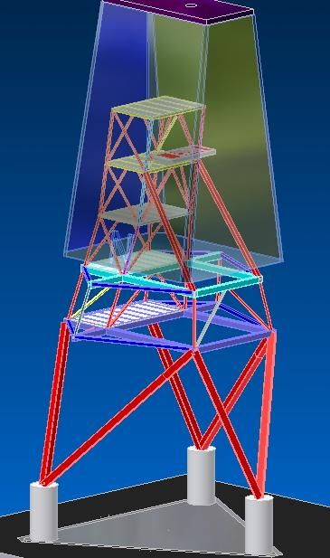
1.2 Heritage for measuring, large aspheric mirrors
         The University of Arizona has developed techniques and facilities for measuring large, highly aspheric optics
such as the 8.4-m diameter f/1.1 primary mirrors for the Large Binocular Telescope (LBT).4 We use an interferometer
with null lens at the center of curvature of the mirror under test.5 The null lens that compensates the aspheric departure
consists of a set of lens elements that are aligned using axisymmetry. This system is then calibrated using a computer
generated hologram.6
         The testing for GMT requires a new methods and hardware due to the off-axis nature of the segment, the very
large aspheric departure, and the long radius of curvature. We cannot use axisymmetry as we have in the past and we
cannot use a simple CGH because the magnitude of the aspheric departure is so great. In addition, because the GMT
radius of curvature is so long, we do not have access to the radius of curvature in our shop. These issues are shown
graphically in Figure 3.

              Heritage (LBT)                                                                 GMT
                                                                                    14.5 mm aspheric departure
        1.4 mm aspheric departure

                                                 Test wavefront
                                                defined to match
                                                 aspheric shape
                                                    of mirror

                                               roof

                                               Test
                                              optics

 Axisymmetric                                                                       No Axisymmetry
 Test optics at ~20 meters                                                          Light path defined by GMT is much
 Light from optical test is only                                                    larger
 200 mm diameter near the test
                                                         20 m
 optics – allows direct                                                             (~3.5 meters across at the top of
 measurement of test system                                                         our tower)

                                           8.4-m LBT
                                                                8.4-m GMT segment

Figure 3. The shape measurement of the GMT segments provides several new challenges, the amount of aspheric departure is large
and non-axisymmetric, and the long radius of curvature does not allow direct access in our shop.

         As a stepping stone to GMT, we developed an interferometric test for a 1.7-m off axis parabola, which is
roughly 1/5 scale for GMT.7 This design uses a tilted spherical mirror to compensate most of the aspheric departure. In
addition, a computer generated hologram (CGH) provides both the residual wavefront correction and alignment
references for the system. The optical test layout and the tower design are shown in Figure 4.
          The different patterns on this complex CGH are used to provide optical references for the alignment of the CGH
relative to the interferometer, for the positions of tooling balls that define the position of the spherical mirror, and for
defining the nominal location of the 1.7-m mirror under test.8 (See Figure 5.) The 10-µm positional tolerance for the
CGH and the mirror were achieved using these references. This optical system was successfully used to guide the
polishing of this highly aspheric mirror.9

                                               Proc. of SPIE Vol. 6273 62730M-3
10 cm hologram
15 cm lens
interferometer
1.7 m off-axis mirror
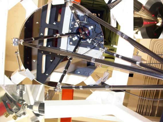
Figure 4. The 1.7-m off axis mirror, which is 1/5 scale for the GMT segments, was measured using a null corrector consisting of a
tilted spherical mirror and a complex computer generated hologram. The assembly was mounted in a tower above the 1.7-m mirror.
10 cm CGH pattern for measurement of 1.7-m mirror
(Each line here represents 350 lines in the real pattern)
3-segment CGH
creating crosshair
CGH
Main CGH
Substrate Metering
alignment rod wI
CGH
LVDT 5
Lens
Ball at focus SPherica\
mirror
(((((Ii ))J11)1'))))))))))
We 4 CGHs creating
beams for
spherical mirror
alignment
CGH creating
clocking line
S
Figure 5. The CGH used 10 total patterns, used for alignment in addition to wavefront correction. The different patterns provide
reference for aligning the CGH to the interferometer, aligning the 50 cm mirror, and positioning the 1.7-m mirror. The spherical
mirror position was determined using four tooling balls. The lateral position of each ball was defined by light from the CGH and the
axial position defined using mechanical metering rods as shown.
Proc. of SPIE Vol. 6273 62730M-4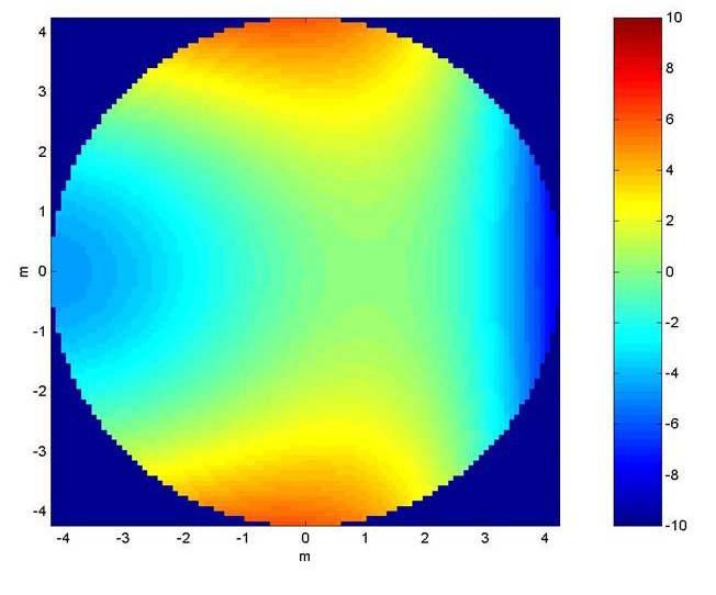
2. DESIGN AND ANALYSIS OF THE INTERFEROMETRIC TEST
        The interferometric test was designed to allow a full aperture null measurement and to fit within the Mirror Lab.
An alignment plan was devised that builds on the experience from the 1.7-m test and will provide reference of sufficient
accuracy to meet the GMT error budget.
2.1 System configuration
          The null corrector for the GMT segment uses a 3.75-m spherical mirror mounted with 14.2°tilt 23 meters from
the GMT segment. This mirror folds the optical path, keeping it within our building, and also compensates much of the
aspheric departure. A second, 75-cm mirror provides an additional relay to a 12-cm CGH, which provides the remainder
of the high-order correction. The layout of this test is shown in Figure 6. Some key features of this test are:
              x Moderate alignment tolerances ~10 µm for CGH, small sphere, ~100 µm for large sphere.
              x Limits the volume of the test to a value that fits within the Mirror Lab
              x Provides internal focus between the two mirrors to be used for alignment
              x Center of curvature for the 3.75-m fold sphere is accessible for in situ testing of this mirror
              x Utilizes vibration insensitive interferometer from 4D Technologies
              x Builds on experiences and methods from the test of the 1.7-m mirror
                                                                                                 3.75-m fold sphere
         CGH pattern                                                                             tilted 14.2°
   (1 line shown represents 400)                     Vibration
                                                    insensitive
                                              interferometer
                                                 Interferometer

                                      CGH

                                                                                                        23
                                                                                                       meters

                                     75-cm
                                   0.75      mirror
                                        m sphere

                                       Axis of parent
                                         asphere

                Center of curvature for 3.75-m fold                           GMT segment
                                                                             8.4-m GMT segment
                                            sphere

                       Figure 6. Optical layout for the interferometric test for the off axis GMT mirror segment

         The test configuration also introduces new challenges:
             x Requires fabrication and mounting of 3.75-m diameter high-quality mirror
             x Requires major reconstruction of the Mirror Lab test tower
             x Fine alignment must be performed by moving the 8.4-m mirror, rather than by moving the test optics.

                                                  Proc. of SPIE Vol. 6273 62730M-5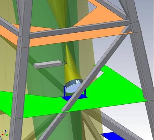
2.2 Alignment methodology
         The alignment method for the optical test builds on methods that have been successfully implemented for other
tests. The alignment of the CGH to the interferometer and the subsequent alignment of the 75-cm spherical mirror can
be accomplished using the same techniques as those presented above for the testing of the 1.7-m mirror. We will require
good mechanics for the mounts, but we will not require thermal stability of invar; steel will be adequate.
         We make explicit use of the intermediate focus between the two mirrors for alignment and calibration of the
system. In this region, we place a small 120x70-mm computer generated hologram that reflects light back through the
75-cm mirror and CGH into the interferometer. We can use the reflected wavefront as feedback for positioning this
CGH in the optical beam in the same way as we align the CGH for null corrector calibration.6 This CGH will be
kinematically located so we can insert it for alignment testing, and remove it for operation. Then this CGH serves three
functions:
             x It provides an independent test of the wavefront from the main CGH, reflected for the 75 cm mirror.
              x    It provides an alignment datum for positioning the 3.75-m mirror.
              x    Allows additional holograms that to provide alignment cross-checks
         We use a dedicated laser tracker to measure the relative positions of the optics for this test. The laser tracker is
a three-dimensional coordinate measurement system that measured positions of retroreflectors using combination of
gimbal angles and line of sight absolute distance measuring (ADM). Trackers are commercially available that will
achieve 2V accuracy of 50 µm for our measurements. Our requirements, based on the error analysis presented below, are
much looser at ±100 µm.
         We use a laser tracker to determine the relative positions of the intermediate CGH, the 3.75-m fold sphere
(making use of its center of curvature reference), and the GMT segment. The assembly with interferometer, CGH, and
75-cm mirror is then aligned relative to the CGH. We place sphere mounted retroreflectors (SMRs) at key locations and
simply measure their positions using the laser tracker. We use the absolute distance measuring (ADM) mode in the
tracker for these measurements so we do not require an uninterrupted beam. The relative positions of the optics are then
actively controlled using feedback from the laser tracker. This procedure is shown below in Figure 7.

                                                                                                    Alignment CGH pattern
                                                                                          (shown scaled so each line here represents 1000)
 Place alignment CGH at intermediate focus
     Provides wavefront test
     Provides reference for alignment
 1. Align CGH, small mirror using CGH references
    and metering rods (~10 µm tolerances)                                              Laser
 2. Use CGH at intermediate focus. Use this to                                         tracker
    verify alignment, and to define alignment for
    3.75-m sphere
 3. Use laser tracker to define position of 3.75-m
    mirror with respect to CGH
    (100 µm tolerance)
 4. Measure GMT segment position with laser
    tracker                                                                              Uses laser reflection
    (200 µm tolerance)                                                                   from reference targets
                                                                                         Angles + radial distance
 Additional cross-checks provide                                                         are measured to
   redundancy and improved accuracy.                                                     determine position of
                                                                                         target
                   Interferometer at the
                                                                                         Accurate to ~50 µm for
                   center of curvature of fold sphere
                                                                                         this application
                     Real time measurement of shape
                     Reference for locating the mirror

      Figure 7. System alignment method, using CGH at intermediate focus and real time measurements with the laser tracker.

                                                    Proc. of SPIE Vol. 6273 62730M-6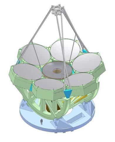
2.3 Error analysis for GMT interferometry
          Detailed error analysis was performed for the GMT optical measurements to guide the engineering and to assure
that the measurement will meet GMT goals. The analysis was performed to determine the effect in the telescope of any
errors in the optical test. In operation in the telescope, we will perform the following sequence:
             1.   Install mirror segments using coarse mechanical measurements
             2.   Measure wavefront using star light
             3.   Move mirror segments to optimize wavefront:
                       a. translate in radial direction
                       b. rotate about segment center (clocking)
                       (There is NO ALLOWANCE for axial spacing adjustment to compensate power.)
             4.   Bend mirrors to correct other shape errors, including power.
The analysis of the test optics simulates the same operations. The effect of imperfect optical testing will be:
x        Shift in the segment positions, which must be limited to ~2 mm
x        Actuator forces required for the active optics, which are budgeted at 25 N rms
x        Residual wavefront errors that are not corrected, which are budgeted as 60% of the mirror structure function.
         Once the telescope is coarsely aligned, the mirror segment positions are adjusted to optimize performance. In
this case the telescope performance is defined by the actuator forces and residual surface errors after bending. We
decompose the allowable rigid body segment motions into two terms, radial position which is a radial shift of the
segment relative to the parent axis, and clocking or rotation about the segment’s center. These motions are optically
equivalent to shape changes as shown in Figure 8

                     1 mm radial motion                                                 50 arcsec clocking
                                                                            (1 mm motion at outer edge of mirror segment)

                                 4.2 µm PV                                                            6.59 µm PV
                                 0.97 µm rms                                                          1.29 µm rms

                                 0.81 µm rms power
                                 0.55 µm rms astigmatism                                              1.28 µm rms astigmatism
                                 0.05 µm rms coma                                                     0.17 µm rms coma
                                 0.02 µm rms trefoil                                                  0.02 µm rms trefoil

              Figure 8. Effective change in optical surface that is seen for rigid body motion of the mirror segments.

          The segments are adjusted to minimize the actuator force required after adjustment. Since astigmatism is a very
“soft” mode, requiring only 13 N rms per µm rms, the radial position is mostly used to compensate power (with modal
stiffness of 38 N rms/ µm rms) and coma (modal stiffness of 150 N rms/µm rms.) rather than astigmatism. The optimal
adjustment for each degree of freedom x was derived using linear algebra to define the residual force, and setting the
derivative to be zero. Equation 1 below shows the result of this derivation:

                                                 Proc. of SPIE Vol. 6273 62730M-7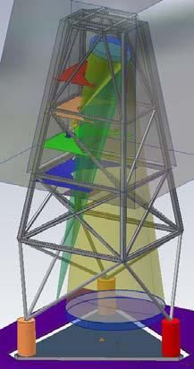
2
                                                                   § wF · wa
                                                             ¦i ai ¨ wa ¸ wxi                                              (Eq. 1)
                                                xoptimal           © i¹          ,
                                                                      2        2
                                                                § wF · § wai ·
                                                            ¦i ¨ wa ¸ ¨© wx ¸¹
                                                                © i¹
where
         xoptimal is the optimal adjustment of radial position or clocking to minimize force,
         ai are the values of Zernike coefficients before making the adjustment (in µm rms),
          wF
              is the mirror stiffness for changing shape that matches Zernike coefficient i (in N rms/µm rms),
          wai
          wai
              is the sensitivity of the Zernike coefficient i to a unit displacement of x.
          wx

         The error analysis for the measurement was performed using a perturbation-type analysis using the optical
design code Zemax™, where each degree of freedom for the optical test was perturbed by the amount defined by its
tolerance and the effect on the optical test was simulated directly. Only the tilt of the segment was adjusted as a
compensator in the model, which will be performed in the real test to bring the light into the interferometer and to “fluff
out” the fringes. The resulting wavefront for the perturbed model was written to a file for subsequent processing.
         The assumption is that the GMT segment would be manufactured with an error identical to the testing error,
which would have a contribution from each of the parameter tolerances. So we simulate the telescope operation with
these errors, one at a time. The segment position is optimized according to the relation above. Then the lowest 16
bending modes are fit and removed from the data. The force required to cause this bending, and the residual errors that
are not corrected are recorded. The residual wavefront errors are compiled in terms of the structure function. This
process is repeated for all of the degrees of freedom for the optical test, resulting in a complete analysis of the errors, as
shown in Table 2.

  Table 2. Result of tolerance analysis for the optical alignment of the GMT null test
                                                               Radial shift       Clocking   Correction force Residual surface
     Element            Parameter         Tolerance (µm)
                                                                 (mm)              (mdeg)        (N rms)         (nm rms)
                    axial displacement           20               0.02              0.25          5.44             11.95
     hologram           tilt about y             10               -0.01             0.16          0.99             2.80
                        tilt about x             10               -0.02             0.02          3.16             8.27
                    axial displacement          100               1.23              -0.05         11.12            15.21
                        tilt about y            100               0.00              3.11          1.88             4.19
   3.75 m sphere
                        tilt about x            100               1.04              -0.04         8.05             20.09
                          radius                250               -0.40             0.01          2.84             3.10
                    axial displacement           20               -0.50             0.02          5.02             6.16
                        tilt about y             10               0.00              -0.10         2.11             3.14
   0.75 m sphere
                        tilt about x             10               0.12              -0.01         3.94             9.80
                          radius                 20               -0.49             0.02          4.98             6.89
   GMT segment      axial displacement          200               0.40              -0.02         4.67             8.56
      sum in
                                                                  1.85              3.13          18.23            33.85
    quadrature

                                                 Proc. of SPIE Vol. 6273 62730M-8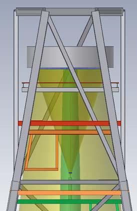
The structure function determined by this error analysis is shown below in Figure 9 where the structure function
for the optical test has been subtracted (in quadrature) from the overall mirror specification, showing the allowable
structure function for the mirror surface after making the allocation for the alignment of the optical test. It is clear from
Table 2 and Figure 9 that the alignment errors assumed for the optical test will not have a significant effect on GMT
performance – the actuators need only apply 18 N rms and the effect on the structure function is not significant.

                                           1000

                                                                            Mirror specification
                                                                            Allowable error after testing
           rms wavefront difference (nm)

                                                                            Optical test

                                           100

                                            10

                                             1
                                             0.01                              0.1                             1                      10
                                                                               separation (meters)
                                                  Figure 9. Structure function defined by the alignment errors in the optical test.

          Additional errors in the optical test will come from the surface figures of the two mirrors, and from the CGH
fabrication errors. These errors will be small, but they will add significant contribution to the testing errors at small
scales. The large fold sphere will provide the largest contribution to this error. The test light reflects twice from the fold
sphere while it only reflects once from the GMT segment, making the surface more sensitive than what one may expect.
We will measure the figure from its center of curvature in situ in the optical test and make appropriate corrections to the
GMT measurements for errors up to ~10 cycles across. We have set a surface slope requirement of 4 nm/cm rms for the
3.75-m mirror and a requirement to map the data to an accuracy of 1.5 cm. The combination of imperfect mapping and
higher order errors that are not backed out is allocated a wavefront structure function budget that is equal to 40% of the
mirror structure function.

                                                                    3. 3.75-METER FOLD SPHERE
         The 3.75-m diameter mirror that we use as a fold sphere, shown in Figure 10, will be manufacture at University
of Arizona as a lightweight casting of low-expansion borosilicate glass using the same process as that used for the large
primary mirrors. Since the fold sphere does not need to be thermally responsive like the primary mirrors, the facesheet
thickness was increased from the nominal 28 mm to 38 mm to reduce the small scale errors from both polishing and
gravity effects. We require this mirror, to be accurate and lightweight
         The 3300-kg fold sphere will be supported face down in the test tower with 48 spring-type actuators, as shown
in Figure 12. These apply controlled force, measured with an in-line load cell, and can be adjusted periodically if

                                                                         Proc. of SPIE Vol. 6273 62730M-9
necessary. The position of the mirror is constrained using hard points that are nominally unloaded. The actuators will be
mounted into a steel cell shown in Figure 11.

                                3759
                                 375mm
                                  9
                                  mm                                      455
                                                                          455
                                                                          mm                 Pt— —
                                                                          mm

Figure 10. The 3.75-m fold sphere will be made as a lightweight borosilicate casting using the spinning oven at the University of
Arizona Mirror Lab. Preparations are now underway to build the mold onto the 8-m hearth.

                                                                                                                   Manual
                                                                                                                     force
                                                                                                                  adjustment

Figure 11. The 3.75-m fold sphere will hang from 48 actuators    Figure 12. The support actuators use in-line load spreaders and
from a steel cell.                                               allow a simple mechanical adjustment.

                                                     4. TEST TOWER
         The optical test for the GMT primary mirror segments requires a new test tower to be constructed at the
Steward Observatory Mirror Lab at the University of Arizona. The design of this tower was optimized to allow the
testing of GMT and other telescope mirrors, yet not to expand the Mirror Lab. The Mirror Lab is located under the east
wing of Arizona stadium, where expansion is extremely difficult. The test tower extends through a thimble in the roof.

                                                                                           Back of
                                                                                           football
                                                                                           bleachers

                                                                                           Thimble

                                                                                       Steward
                                                                                       Observatory
                                                                                       Mirror Lab

          Figure 13. Steward Observatory Mirror Lab is located under the bleachers of Arizona Stadium.

                                               Proc. of SPIE Vol. 6273 62730M-10
3.75 m
sphere
interferometer
fold flat and
hologram
3.75 m 0.75 m sphere
sphere
center of
curvature GMT
segment
Figure 14. Layout of the GMT test in the new test tower, showing the in situ measurement of the 3.75-m fold sphere as well as the
GMT segment measurement.
The GMT can be tested within the existing Mirror Lab building, but the original tower, built in 1990, is not
sufficient to support the large mirror at the top. The tower is being replaced by a significantly taller and more massive
structure that will enable GMT testing, as well as other large 6.5-m and 8.4-m mirrors, including the dual primary-
tertiary mirror for LSST. The new tower will stand 29 meters tall, and will require 80 tons of steel. The structure is
designed to achieve 4.8 Hz for its lowest mode with the 9-ton fold sphere and cell mounted at the top.
Figure 15. The old test tower at the Mirror Lab (on left) is being Figure 16. The test tower is built onto columns on a floating
replaced by a larger and stiffer structure (on right). triangular concrete pad which is 15 m on a side and 3 m
thick. The pad is supported by 44 pneumatic isolators.
The single central segment will be much easier to measure as this mirror is axisymmetric, without such large
aspheric departure. To measure this mirror, the 3.75-m fold sphere will be tilted so points straight downward. This
mirror folds the path and compensates nearly all of the aspheric departure. A small computer generated hologram
provides the additional correction. Similar alignment methods can be used as described above, although this test is not
nearly as sensitive to alignment errors.
Proc. of SPIE Vol. 6273 62730M-113.75-m fold sphere
tilted so it points
straight down
Cone defined by
light from outer
edge of mirror
50 mm CGH
Cone defined by compensates
light from edge remaining 20 µm
of central hole aspheric departure
GMT central
segment Vibration
insensitive
interferometer
Figure 17. The GMT central segment will be tested using similar hardware, but the 3.75-m fold sphere will be tilted nadir pointing.
5. CONCLUSION
Work is now underway at the University of Arizona to complete detailed designs and to build the hardware to
perform the interferometric measurements of the GMT mirror segments.
6. REFERENCES
1. M. Johns, “The Giant Magellan Telescope (GMT)”, in Ground-based and Airborne Telescopes, ed. L. M. Stepp, Proc. SPIE
6267 (2006).
2. H. M. Martin, J. R. P. Angel, J. H. Burge, B. Cuerden, W. B. Davison, M. Johns, J. S. Kingsley, L. B. Kot, R. D. Lutz, S.
M. Miller, S. A. Shectman, P. A. Strittmatter and C. Zhao, “Design and manufacture of 8.4 m primary mirror segments and
supports for the GMT”, in Optomechanical Technologies for Astronomy, ed. E. Atad-Ettedgui, J. Antebi and D. Lemke,
Proc. SPIE 6273 (2006; these proceedings).
3. J. H. Burge, T. Zobrist, L. B. Kot, H. M. Martin and C. Zhao, “Alternate surface measurements for GMT primary mirror
segments”, in Optomechanical Technologies for Astronomy, ed. E. Atad-Ettedgui, J. Antebi and D. Lemke, Proc. SPIE
6273 (2006; these proceedings).
4. H. M. Martin, R. G. Allen, J. H. Burge, L. R. Dettmann, D. A. Ketelsen, S. M. Miller and J. M. Sasian, “Fabrication of
mirrors for the Magellan Telescopes and the Large Binocular Telescope”, in Large Ground-based Telescopes, ed. J. M.
Oschmann and L. M. Stepp, Proc. SPIE 4837, p. 609 (2003).
5. J. H. Burge, L. R. Dettmann, and S. C. West, “Null correctors for 6.5-m f/1.25 paraboloidal mirrors,” OSA Trends in Optics
and Photonics Vol. 24, Fabrication and Testing of Aspheres, J. S. Taylor, M. Piscotty, and A. Lindquist eds. (Optical
Society of America, Washington, DC 1999) pp. 182-186.
6. J. H. Burge, “Certification of null correctors for primary mirrors,” in Advanced Optical Manufacturing and Testing IV, J.
Doherty, Editor, Proc. SPIE 1994, 248-259 (1993).
7. C. Zhao, R. Zehnder, J. H. Burge, H. M. Martin, “Testing an off-axis parabola with a CGH and a spherical mirror as null
lens,” in Optical Manufacturing and Testing VI, H. P. Stahl, Ed., Proc. SPIE 5869, 58690X (2005).
8. R. Zehnder, J. H. Burge and C. Zhao, “Use of computer-generated holograms for alignment of complex null correctors”, in
Optomechanical Technologies for Astronomy, ed. E. Atad-Ettedgui, J. Antebi and D. Lemke, Proc. SPIE 6273 (2006; these
proceedings).
9. H. M. Martin, J. H. Burge, S. D. Miller, B. K. Smith, R. Zehnder and C. Zhao, “Manufacture of a 1.7-m prototype of the
GMT primary mirror segments”, in Optomechanical Technologies for Astronomy, ed. E. Atad-Ettedgui, J. Antebi and D.
Lemke, Proc. SPIE 6273 (2006; these proceedings).
Proc. of SPIE Vol. 6273 62730M-12You can also read