Triboelectric-Thermoelectric Hybrid Nanogenerator for Harvesting Energy from Ambient Environments - Zhong Lin Wang
←
→
Page content transcription
If your browser does not render page correctly, please read the page content below
FULL PAPER
Hybrid Nanogenerator                                                                                                       www.advmattechnol.de

Triboelectric–Thermoelectric Hybrid Nanogenerator
for Harvesting Energy from Ambient Environments
Ying Wu, Shuangyang Kuang, Huayang Li, Hailu Wang, Rusen Yang, Yuan Zhai,*
Guang Zhu,* and Zhong Lin Wang*

                                                                                                  with different converting mechanism
Recently developed triboelectric nanogenerators (TENG) with advantages                            have been reported, such as electromag-
of a low fabrication cost, high output voltage, and high energy conversion                        netic generators,[4,5] piezoelectric gen-
                                                                                                  erators,[6–8] electrostatic generators,[9–11]
efficiency have shown potential applications in harvesting ambient environ-
                                                                                                  and triboelectric nanogenerators.[12–14]
ment energy. However, the heat energy produced and wasted during the                              Triboelectric nanogenerators have shown
triboelectric energy generation process limits the output of TENG. One                            advantages of a low fabrication cost, high
approach is to design TENG based on a noncontact mode to minimize                                 output voltage, and high energy conver-
the energy loss. The other approach is to scavenge the lost energy with a                         sion efficiency. However, heat energy is
supplementary nanogenerator. In this work, triboelectric–thermoelectric                           produced and wasted during the tribo-
                                                                                                  electric energy generation process, which
hybrid nanogenerator (TTENG) is fabricated to harvest the energy from
                                                                                                  limits the output of triboelectric nano-
ambient environment and the thermal energy from the temperature                                   generators (TENG).[15] On the one hand,
difference induced by r-TENG friction. At a rotation rate of 500 rpm, r-TENG                      noncontact approaches have been used to
can produce a constant open-circuit voltage (Voc) of 200 V and a short-circuit                    minimize the energy loss of TENG. On
current (Isc) of 0.06 mA. The thermoelectric nanogenerator (TMENG)                                the other hand, it is possible to scavenge
                                                                                                  the lost energy to improve the output per-
with a size of 16 cm2 can produce a Voc of 0.2 V and an Isc of 20 mA. The
                                                                                                  formance of TENG.[16,17] Although pyroe-
experimental results show that the TTENG is a promising method to harvest                         lectric nanogenerators harvesting thermal
the ambient mechanical energy.                                                                    energy from the friction-induced tem-
                                                                                                  perature fluctuation have been reported,
                                                                                                  different thermal harvesting efforts are
1. Introduction                                                              still needed to enhance the total efficiency of the generators
                                                                             that integrates the energy harvesters and the energy storage
With an increasing energy demands, more and more new gen-                    devices.[18–20]
erators have been developed to harvest ambient environment                      Here, we present triboelectric–thermoelectric hybrid nano-
energy,[1–3] which show potential applications in daily life,                generator (TTENG), which can harvest mechanical and
industrial plants, agriculture, and military. Many generators                thermal energy. The TTENG is composed of a 2D rotary TENG

Dr. Y. Wu, Dr. Y. Zhai                                                       Prof. R. Yang
College of Electrical and Information Engineering                            School of Advanced Materials and Nanotechnology
Chongqing University of Science &Technology                                  Xidian University
Chongqing 401331, China                                                      Xian 710126, China
E-mail: cquzhy@cqust.edu.cn                                                  Prof. G. Zhu
Dr. S. Kuang, Dr. H. Li, H. Wang, Prof. G. Zhu, Prof. Z. L. Wang             Department of Mechanical, Material and Manufacturing Engineering
CAS center for Excellent in Nanoscience                                      University of Nottingham Ningbo China
Beijing Key Laboratory of Micro-nano Energy and Sensor                       Ningbo 315100, China
Beijing Institute of Nanoenergy and Nanosystems                              Prof. G. Zhu
Chinese Academy of Sciences                                                  New Materials Institute
Beijing 100083, China                                                        University of Nottingham Ningbo China
E-mail: zhuguang@binn.cas.cn; zhong.wang@mse.gatech.edu                      Ningbo 315100, China
Dr. S. Kuang, Dr. H. Li, H. Wang, Prof. Z. L. Wang                           Prof. Z. L. Wang
School of Nanoscience and Technology                                         School of Materials Science and Engineering
University of Chinese Academy of Science                                     Georgia Institute of Technology
Beijing 100049, China                                                        Atlanta, GA 30332-0245, USA
      The ORCID identification number(s) for the author(s) of this article
      can be found under https://doi.org/10.1002/admt.201800166.

DOI: 10.1002/admt.201800166

Adv. Mater. Technol. 2018, 1800166                                1800166 (1 of 7)              © 2018 WILEY-VCH Verlag GmbH & Co. KGaA, Weinheim
www.advancedsciencenews.com                                                                                                   www.advmattechnol.de

(r-TENG) and thermoelectric nanogenerator (TMENG) based                     is composed of alternately connected Bi2Te3-based P-type and
on Seebeck effect. By harvesting the majority of mechanical                 N-type semiconductors.
energy during the rotating motion, the r-TENG can produce a
constant open-circuit voltage (Voc) of 2.5 V and a short-circuit
current (Isc) of 0.4 mA at a rotation rate of 500 rpm through               2.2. Electrical Characterizations
the transformer. The TMENG with a size of 16 cm2 can harvest
thermal energy generated by the r-TENG and produce a Voc of                 The operation of the r-TENG sensor relies on a relative rotation
0.2 V and an Isc of 20 mA. The TTENG can produce a Voc of                   between the rotator and the stator, in which a unique coupling
4.6 V and an Isc of 0.4 mA at a rotation rate of 500 rpm when               between triboelectrification and electrostatic induction gives
the TENG and the TMENG are in a serial connection. The                      rise to an alternating flow of electrons between electrodes. At
TTENG has been demonstrated to charge a capacitor of large                  the initial state, the rotator is just in contacts with the stator,
capacitance and as a power source for a temperature detection               leading to a charge transfer on the contact surface. A negative
module. With these outstanding performances, the TTENG is                   charge is produced on the PTFE surface, and a positive charge
proven to be a promising method to harvest ambient mechan-                  is produced on the conductive tape.
ical energy.                                                                   Under the open-circuit condition, electrons cannot transfer
                                                                            between electrodes. The open-circuit voltage can be defined
                                                                            as the electric potential difference between the two electrodes,
2. Results and Discussion                                                   namely, Voc = UA − UB. State I in Figure 1b represents the max-
                                                                            imum Voc, which corresponds to the maximum potential on
2.1. Structural Design and Working Principle of the TTENG                   electrode A and the minimum potential on electrode B. When
                                                                            the rotator begins to run, Voc diminishes and reaches zero once
The presented hybrid generator has a multilayered structure,                the rotator reaches the midpoint (state II in Figure 1b). As the
which consists of two parts, a rotator and a stator, as sketched            rotator continues to move, the potential difference increases
in Figure 1a. The rotator is composed of three layers: a rigid              reversely. When it reaches the terminal point, the reverse poten-
substrate layer made of acrylic, a layer of sponge and a positive           tial difference reaches its maximum (state III in Figure 1b).
electrification layer made of nylon. The rotator with a diameter            Further rotation beyond the final state causes the Voc to change
of 8 cm is a collection of radially arrayed sectors separated by            periodically because of the periodic structure (state IV in
equal-degree intervals.                                                     Figure 1b).
   The stator has a vertically stacked structure consisting of                 The operation of the TMENG relies on the Seebeck effect
three layers. First, a layer of Cu was deposited onto an acrylic            that refers to the phenomenon of the potential difference gener-
substrate as two complementary electrodes with the same con-                ated by the temperature difference. The temperature difference
figuration as the positive electrification layer. Then, a layer of          between TMENG’s upper end and lower end is zero before the
polytetrafluoroethylene (PTFE) was spread out on the Cu sur-                rotator contacts the stator. When the rotator contacts the stator
face. The TMENG was inserted between the electrodes and the                 and begins to rotates, the heat energy produced by friction is
substrate. The upper surface of the TMENG is completely in                  transferred to the upper end of the TMENG (Figure 1b). As a
contacts with the electrodes plane, which is helpful to harvest             result, electricity is generated due to the Seebeck effect.
the thermal energy produced by the r-TENG and thus improve                     The potential difference can be calculated from the following
the energy conversion efficiency.                                           equation[21]
   The TMENG has five layers, as shown in Figure 1a. The first
and the last layer are insulators that transmit temperature. The                      T2

second and the fourth layers are conductors. The third layer
                                                                            V =   ∫
                                                                                  T1
                                                                                           (SB (T ) − SA (T ))dT (1)

Figure 1. Overall structure and working principle of the TTENG. a) Schematic illustration of the TTENG. b) Detailed schematics of operating principle
of the hybrid cell, which include four parts, one initial state (I), two intermediate states (II, IV), and one final state (III).

Adv. Mater. Technol. 2018, 1800166                               1800166 (2 of 7)                © 2018 WILEY-VCH Verlag GmbH & Co. KGaA, Weinheim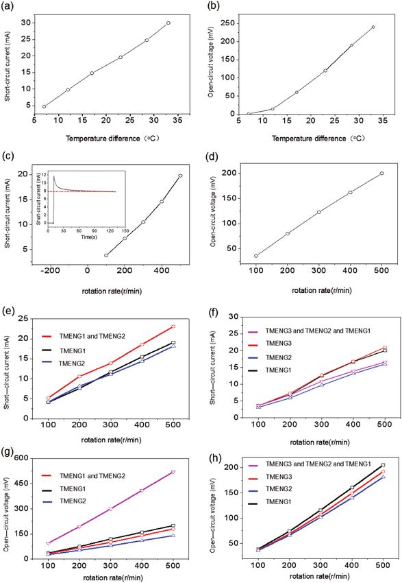
www.advancedsciencenews.com                                                                                               www.advmattechnol.de

Figure 2. The output of the r-TENG. a) The output voltage of the r-TENG. b)The peak current of the r-TENG. c) The peak voltage of the r-TENG con-
nected to a transformer. d) The peak current of the r-TENG connected to a transformer.

   SA and SB are the corresponding Seebeck coefficients, and              difference reaches ≈33 °C, Voc can reach ≈250 mV and Isc can
the equation above can be converted into another form once SA             reach 30 mA. To observe the output signal resulting from the
and SB do not change with the temperature.                                friction-induced temperature fluctuation during the triboelec-
                                                                          tric process, the performance of TMENG was measured in all
V = (SA − SB )(T2 − T1 )                                           (2)    processes of the rotational motion. To compare with r-TENG,

                                                                          the relationship between the corresponding stable output signal
   The performance of the r-TENG was measured while the                   of TMENG and the rotation rate was measured. As shown in
rotator was sliding on the stator periodically. As shown in               Figure 3c, with the increase of rotation rate, the short-circuit
Figure 2a, the open-circuit voltage oscillated with a peak-to-            current also increased. The increasing rate of the short-circuit
peak value of 200 V at a rotation rate of 500 rpm. The open-              current is faster with the increase of rotation rate. When the
circuit voltage does not change with the increasing of rotation           rotation rate was set to 500 rpm, the short-circuit current of
rate because the voltage is only dependent on the position of             TMENG was able to reach 20 mA, which is much larger than
the rotator, which has been reported previously.[22] The short            that of the r-TENG. It can also be observed that the output
circuit current was measured to be an AC output. As shown                 voltage of TMENG was low and only reached 200 mV when the
in Figure 2b, the short circuit current Isc increases with the            rotation rate was set to 500 rpm (Figure 3d).
increase of rotation rate and can reach 60 µA at a rotation rate             The inset of Figure 3c shows the short-circuit current of the
of 500 rpm. Typically, the r-TENG is connected to a transformer           thermoelectric generator. At first, the output short-circuit cur-
to provide power for the load. As shown in Figure 2c,d, with the          rent was low because the temperature difference between the
increase of rotation rate, the open-circuit voltage and the short-        lower and upper ends of TMENG was constant and low. When
circuit current both increase. At the rotation rate of 500 rpm,           the rotator started to rotate, the temperature of TMENG’s upper
Isc and Voc can reach 400 µA and 2.5 V, respectively. The reason          side rose rapidly. Then, the temperature difference between
for the voltage increase is that the inductive reactance is gener-        the lower and upper sides of TMENG reached its maximum,
ated, and the total impedance increased when the transformer              resulting in the instant increase of Isc to its maximum of
is connected. The current changed with the variation of the               12 mA. As time went by, a small amount of heat energy was
rotation rate. Therefore, the transformed voltage increased as            transferred from the upper end to the lower end. Consequently,
the rotation rate increased. The detailed reason was elaborated           Isc decreased and eventually stabilized at 7 mA at a constant
by Zhu.[22]                                                               rotation rate of 200 rpm. It can also be observed from the curve
   As shown in Figure 3a,b, the corresponding open-circuit                that the output short-circuit current did not show any decay
voltage and short-circuit current of the TMENG were meas-                 for a long time after reaching its steady state, which effectively
ured at different temperature differences. There is a linear              proved the reliability of the TMENG for practical applications.
relationship between Isc and temperature difference, as well                 To enhance the thermoelectric current, two TMENGs were
as between Voc and temperature. When the temperature                      connected in parallel, as shown in Figure 3e,f. The output

Adv. Mater. Technol. 2018, 1800166                             1800166 (3 of 7)                © 2018 WILEY-VCH Verlag GmbH & Co. KGaA, Weinheim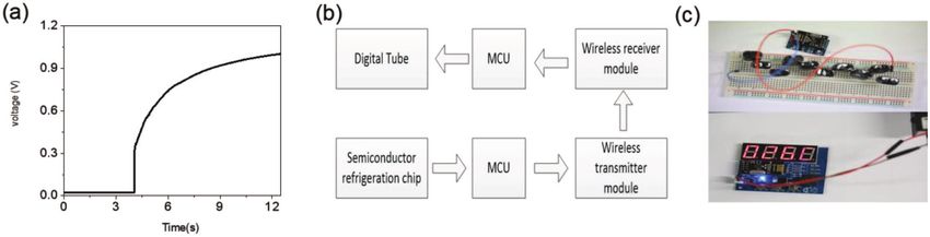
www.advancedsciencenews.com                                                                                                   www.advmattechnol.de

Figure 3. The output of the TMENG. a) The relationship between the current and the temperature difference of one TMENG. b) The relationship
between the voltage and the temperature difference of one TMENG. c) The relationship between the current and the rotation rate of one TMENG.
d) The relationship between the voltage and the rotation rate of one TMENG. e) The relationship between the current and the rotation rate of two
TMENGs in a parallel connection. f) The relationship between the current and the rotation rate of two TMENGs in a serial connection. g) The relation-
ship between the voltage and the rotation rate of three TMENGs in a parallel connection. h)The relationship between the voltage and the rotation rate
of three TMENGs in a serial connection.

short-circuit current of the two TMENGs connected in par-                   single TMENG is different from that of the TMENG when con-
allel is greater than that of the single output, but lower than             nected in parallel. Therefore, part of the electronics will flow
the sum of the single output current because the performance                from one TMENG with a high output current to the other with
of the two TMENGs is not the same. The output current of a                  a low output current, which eventually leads to the fact that

Adv. Mater. Technol. 2018, 1800166                               1800166 (4 of 7)                © 2018 WILEY-VCH Verlag GmbH & Co. KGaA, Weinheim
www.advancedsciencenews.com                                                                                              www.advmattechnol.de

the short-circuit current of TMENGs in a parallel connection             P = UI                                                              (3)
is not a linear superposition of the two separate short-circuit
currents.                                                                    Where U and I are the load voltage and current, respectively.
   To enhance the open-circuit thermoelectric voltage, three              At the rotation rate of 500 rpm, the maximum output power of
TMENGs were connected in serial. As shown in Figure 3g, the               TMENG can reach 16.59 mW (the corresponding voltage is
current output of three TMENGs in serial can reach approx-                0.395 V, current is 42 mA), and the maximum output power of
imately 16 mA at the rotation rate of 500 rpm, because the                r-TENG can reach about 4.32 mW (corresponding voltage is
current output is limited by the minimum current of these                 120 V, current is 0.036 mA). It can be concluded that the TMENG
three devices. As shown in Figure 3h, the voltage output of the           can effectively harvest the thermal energy produced by the r-TENG.
TMENGs connected in serial is a sum of the voltage outputs of                As a demonstration for the charging ability of the TTENG, a
the three individual devices and reaches more than 500 mV at              22 uF capacitor was charged when the TMENG and the r-TENG
the rotation rate of 500 rpm.                                             were in a serial connection (Figure 5e), and the corresponding
                                                                          charging result is shown in Figure 5f (the red curve). The result
                                                                          of the capacitor solely charged by the r-TENG is shown by the
2.3. Application                                                          blue curve in Figure 5f. It could be observed that during the
                                                                          same charging time (≈10 s), the charging voltage for r-TENG
A temperature detection system was successfully driven by the             and TTENG could reach ≈1.35 and 1.85 V, respectively. The
TMENG, demonstrating its application performance. A capac-                charging power could be derived from the following equations
itor with a capacity of 0.5 F was used to store the electricity gen-
erated by the TMENG. The charge voltage curve at a rotation              W = CU 2 /2                                                         (4)
rate of 800 rpm is shown in Figure 4a. From the voltage curve,
it can be observed that the voltage can reaches 0.3 V instanta-
                                                                         P = W /T                                                            (5)
neously and gradually stabilizes at 1 V in 8 s. The temperature
detection system can be powered by ten capacitors connected in
parallel. As shown in the Figure 4b,c, the real-time temperature          where C is the capacitance of the charging capacitor, U is the
can be detected and sent to the display module, which demon-              voltage of the charging capacitor, W is the charging energy of
strates the TMENG’s predominant application in a self-powered             the charging capacitor, P is the power of the charging capac-
temperature monitor.                                                      itor, and T is the charging time. From the equations above, the
   Furthermore, the output performance of TTENG was meas-                 charge efficiency of TTENG is calculated to increases by 87%
ured. To get the maximum output voltage, the r-TENG and the               compared to r-TENG.
TMENG are in a serial connection, as shown in Figure 5a. The
corresponding short-circuit was shown in Figure 5b. The output
of the TTENG was utilized to power up the light emitting diode            3. Conclusions
(LED) first. When powered by the TTENG, the LED showed
a strong illumination intensity, as shown in the red areas in             In summary, we have presented a TTENG composed of r-TENG
Figure 5b. When the LED was only powered by r-TENG, the                   and TMENG to effectively harvest the ambient mechanical
LED dimmed gradually and luminance was hardly observed, as                energy. The output power of TTENG was improved greatly
shown in the blue areas in Figure 5b.                                     because the TMENG could harvest the heat energy created
   The peak power densities were measured with different load             by the friction motion of r-TENG. For the r-TENG, the output
resistances at the rotation rate of 500 rpm. As the load resist-          power density was able to reach 0.47 mW cm2 at a rotation
ance increased, the power densities for TMENG and TENG                    rate of 500rpm. The open-circuit voltage and the short-circuit
were enhanced first and then dropped. The maximum peak                    current of TMENG were roughly proportional to the tempera-
power density for TMENG was ≈10.5 W m−2 (Figure 5c) at a                  ture difference. The open-circuit voltage and the short-circuit
corresponding load of 6 Ω. The output power P can be calcu-               current increased with the rotation speed. These experimental
lated from the following equation                                         results showed that the output of TMENG was mainly affected

Figure 4. Output performance of a TMENG. a) The voltage curve of a supercapacitor (0.5 F) charged by a TMENG. b) The flow chart of a temperature
detection system powered by a TMENG. c) The real display of the temperature detection system powered by a TMENG.

Adv. Mater. Technol. 2018, 1800166                            1800166 (5 of 7)                © 2018 WILEY-VCH Verlag GmbH & Co. KGaA, Weinheim
www.advancedsciencenews.com www.advmattechnol.de
Figure 5. Output performance of the TTENG. a) The voltage of r-TENG and TTENG. b) The current of r-TENG and TTENG. c) The relationship between
the instantaneous power density and the resistance of the external load for TMENG. d) The relationship between the instantaneous power density
and the resistance of external load for r-TENG. e) The circuit used to integrate the r-TENG and the TMENG. f) The charge voltage curve of r-TENG
and TTENG.
of the rotator. (3) A layer of sponge (1 cm) and then a layer of nylon
by the temperature difference. Under the short-circuit condi-
(0.01 mm) were pasted on the rotator in sequence. Stator: (1) The laser
tion, a rising curve of the current was observed at a rotation cutter was used to cut a square-shaped acrylic sheet as a substrate with
rate of 500 rpm. The output signal of the TMENGs in serial a dimension of 13 cm by 13 cm by 4 mm. (2) Four through-holes were
and parallel modes was measured. A high DC output with a drilled on the edge of the substrate, with which the substrate can be
power density of 10.5 W m−2 was achieved at a rotation rate of fixed on the experiment platform. (3) The laser cutter was used to cut
500 rpm, and a temperature detection system was successfully a square-shaped through-hole at the center of a 4 cm × 4 cm substrate;
driven. Furthermore, it was demonstrate that the TTENG’s (4) The laser cutter was used to create trenches on top of the substrate,
and these trenches define the patterns of the two sets of complementary
output was able to charge a capacitor, and the charging rate radially arrayed electrodes. (5) The TMENG was embedded into the
was about three times of the charging rate of a r-TENG. These through-holes, and two lead wires were connected to the TMENG. (6) An
outstanding performances of TTENGs demonstrate their electron-beam evaporator was used to deposit a layer of Cu (200 nm) on
potential application to harvest ambient mechanical energy. the substrate. (7) Two lead wires were connected to the Cu electrodes.
(8) A layer of PTFE (0.07 mm) was pasted onto the electrode layer.
Setups of the Electrical Measurement: (1) A rotary motor was mounted
in an inverted way on a 3D linear positioner. (2) The rotator was fixed on
the D-profile shaft of the rotary motor. (3) The linear positioner was used
4. Experimental Section to adjust the height of the rotator so that the rotator and the stator were
Fabrication of the TTENG: Rotator: (1) A laser cutter was used to in firm contact. (4) The position of the linear positioner was adjusted so
cut a disc-shaped acrylic substrate with patterns that consist of radially that the rotator and the stator were aligned in a coaxial alignment. (5) The
arrayed sectors. The rotator has a diameter of 8 cm and a thickness of thermometer was used to record the temperature difference. (6) A keithley
1 cm. (2) A through-hole that has a D-profile was drilled at the center 6514 system electrometer was used to measure voltages and currents.
Adv. Mater. Technol. 2018, 1800166 1800166 (6 of 7) © 2018 WILEY-VCH Verlag GmbH & Co. KGaA, Weinheimwww.advancedsciencenews.com www.advmattechnol.de
Acknowledgements [4] M. Duffy, D. Carroll, Proceeding of IEEE 35th Annual Power Elec-
tronics Specialists Conference, Aachen, June 2004.
The research was supported by National Key R & D Project from [5] F. R. Fan, W. Tang, Y. Yao, J. Luo, C. Zhang, Z. L. Wang,
Ministry of Science and Technology, China (Grant No. 2016YFA0202701 Nanotechnology 2014, 25, 135402.
& 2016YFA0202703). This research was funded by National Science [6] C. J. Hu, Y. H. Lin, C. W. Tang, M. Y. Tsai, W. K. Hsu, H. F. Kuo, Adv.
Foundation of China (Grant No. 51572030). This research was also Mater. 2011, 23, 2941.
funded by Chongqing Research Program of Basic Research and Frontier
[7] W. S. Jung, M. J. Lee, M. G. Kang, H. G. Moon, S. J. Yoon,
Technology (No. cstc2016jcyjA0236 and cstc2016jcyjA0677) and
S. H. Baek, C. Y. Kang, Nano Energy 2015, 13, 174.
Research Foundation of Chongqing University of Science & Technology
[8] H. Y. Li, L. Su, S. Y. Kuang, Y. J. Fan, Y. Wu, Z. L. Wang, G. Zhu,
(No. ck2017zkzd005).
Nano Research 2017, 10, 785.
[9] N. Gogneau, E. Galopin, L. Travers, Phys. Status Solidi RRL 2014, 8,
414.
Conflict of Interest [10] A. C. M. De Queiroz, Circuits and Systems (ISCAS), 2013 IEEE Inter-
national Symposium on., IEEE, Beijing, May 2013.
The authors declare no conflict of interest. [11] A. C. M. D. Queiroz, Circuits and Systems (ISCAS), 2016 IEEE Inter-
national Symposium on., IEEE, Montréal, May 2016.
[12] A. C. M. De Queiroz, Electrostatic Energy Harvesting Without Active
Keywords Control Circuits, IEEE, New York, USA 2014.
[13] F. R. Fan, Z. Q. Tian, Z. L. Wang, Nano Energy 2012, 1, 328.
ambient environment harvester, hybrid nanogenerator, thermal energy [14] G. Zhu, C. Pan, W. Guo, C. Y. Chen, Y. Zhou, R. Yu, Z. L. Wang,
harvester, thermoelectric nanogenerator, triboelectric nanogenerator Nano Lett. 2012, 12, 4960.
[15] Y. Yang, W. Guo, K. C. Pradel, G. Zhu, Y. Zhou, Z. L. Wang, Nano
Received: May 18, 2018 Lett. 2012, 12, 2833.
Revised: July 2, 2018 [16] K. Zhang, X. Wang, Y. Yang, Z. L. Wang, ACS Nano 2015, 9,
Published online: 3521.
[17] Z. L. Wang, J. Chen, L. Lin, Energy Environ. Sci. 2015, 8, 2250.
[18] Y. Yang, J. H. Jung, B. K. Yun, F. Zhang, K. C. Pradel, Adv. Mater.
2012, 24, 5357.
[1] Y. K. Tan, S. K. Panda, IEEE Trans. Ind. Electron. 2011, 58, 4424. [19] Y. Yang, S. Wang, Y. Zhang, Z. L. Wang, Nano Lett. 2012, 12,
[2] K. Ma, Y. Zheng, S. Li, K. Swaminathan, X. Li, Y. Liu, J. Sampson, 6408.
Y. Xie, V. Narayanan, High Performance Computer Architecture [20] Y. Zi, L. Lin, J. Wang, S. Wang, J. Chen, X. Fan, P. K. Yang, F. Yi,
(HPCA), 2015 IEEE 21st International Symposium on., IEEE, Z. L. Wang, Adv. Mater. 2015, 27, 2340.
Burlingame, February 2015. [21] Z. H. Dughaish, Phys. B: Condens. Matter 2002, 322, 205.
[3] V. Marian, B. Allard, C. Vollaire, J. Verdier, IEEE Trans. Power [22] G. Zhu, J. Chen, T. Zhang, Q. Jing, Z. L. Wang, Nat. Commun. 2014,
Electron. 2012, 27, 4481. 5, 3426.
Adv. Mater. Technol. 2018, 1800166 1800166 (7 of 7) © 2018 WILEY-VCH Verlag GmbH & Co. KGaA, WeinheimYou can also read