Design and function of the Veritas charge air systems - Veritas AG
←
→
Page content transcription
If your browser does not render page correctly, please read the page content below

Design and function of the Veritas charge air systems

Connecting, sealing and transporting –
these are the functions performed by Veritas products in motor vehicles.
          However, there is a lot more to this than you may initially think.
Table of contents

Function of the charge air system               4

Description of various systems                  6

A typical charge air duct                       8

Emissions legislation for passenger vehicles   13

Simulation and testing                         15

Outlook		                                      19

                                                    |3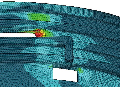
1. Function of the charge air system
    Increasing the engine performance of vehicles fitted with a combustion engine has         Cold air contains significantly more oxygen molecules than hot air, and cooling the
    always been a key focus of engine developers.                                             charge air therefore leads to a higher oxygen content in the combustion chamber.
                                                                                              This results in greater engine power output and torque, as well as reduced fuel con-
    There are various ways to increase engine output. The obvious approaches to this          sumption and lower exhaust emissions.
    include increasing displacement, increasing the number of cylinders, allowing the
    engine to turn at a higher speed and increasing fuel combustion. However, all of          The intercooler is a heat exchanger which is fitted to all turbocharged vehicles and
    these measures come with undesirable side-effects, such as additional costs,              is generally positioned between the turbocharger and the throttle valve. The compo-
    consumption, weight, wear or the need for a greater air supply and thereby a stronger     nents responsible for transporting the air in the charge air system are referred to as
    vacuum. The solution? Compressing the intake air (for example, using a turbocharger)      charge air ducts.
    takes a great deal of the vacuum work away from the engine.
                                                                                              Internal combustion engines are today no longer primarily fitted with turbochargers
    "When residual energy in the exhaust gases is used for                                    to increase performance. The ability to reduce fuel consumption while maintaining
    precompression, this is known as boosting."                                               the same performance is becoming increasingly important. Together with ever more
    (Source: Motair GmbH, http://www.motair.de/index.php?id=167)                              advanced materials development and new production methods, the benefits of
                                                                                              engine boosting are leading to increasing use of turbocharging.
    The stricter exhaust emissions legislation introduced back at the end of the 1980s        (Source: Ostwestfalen-Lippe University of Applied Sciences,
                                                                                              http://www.hs-owl.de/fb6/labore/stroemungsmaschinen/diplom-sm/abgasturbo/geschichte/print.html)
    means that virtually all commercial vehicle engines today employ some form of
    engine boosting, and turbocharged passenger cars have also been on the rise ever
    since. A turbocharger allows the efficiency of a diesel engine to be increased, so that
    it can virtually match the driving performance characteristics of petrol engines.
    The intake air that is compressed by the impeller gets very hot, so it is first cooled
    down in the intercooler before being injected into the combustion chamber.

4 | Veritas charge air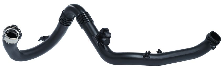
Functions of a typical charge air duct                   Air duct of a turbocharged internal combustion engine

   • Cooling the medium                                                                                      Impeller air flow

   • Ensuring media resistance from inside and outside   Engine cylinder
                                                                                                                                     Turbocharger
                                                                                                                                     Oil inlet
   • Dynamic decoupling
                                                                                          Intercooler                                          Turbine wheel
   • Securing installation and connection                                                                       Impeller
                                                                                                                housing
   • Guaranteeing pressure and temperature resistance                                                                                               Exhaust gas
                                                                                                         Air intake
                                                                                                                                                    outlet
   • Fulfilling crash requirements

   • Maintaining low flow resistance                                                                       Impeller wheel
                                                                                                                                             Boost pressure
   • Enabling movement and tolerance compensation                                                                           Oil outlet       control valve
                                                                    Exhaust gas flow

   • Maintaining low noise generation
                                                         (Source: PowerLine, http://www.turbolader.de/info_pages.php?pages_id=5)
   • Maintaining low permeability

   • Fulfilling design requirements

   • Enabling application of measuring equipment

                                                                                                                                                               |5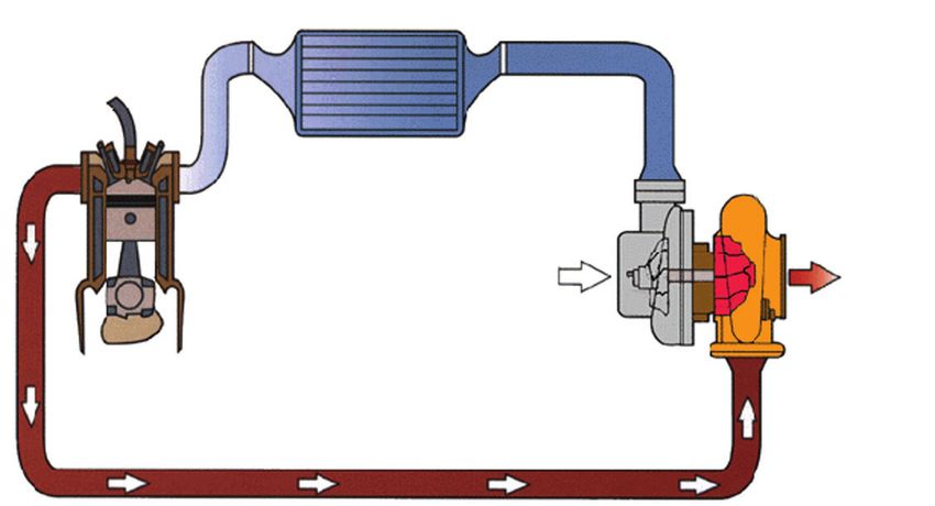
2. Description of various systems
    There are various ways of cooling the hot charge air. Three systems have established   Direct intercooling: Air-air cooler
    themselves here. The design of the charge air ducts varies depending on which of
    these systems is selected:                                                             Here, cooling is performed using a cooler with air flowing over it. The cooler itself is
                                                                                           generally positioned at the front of the vehicle. The charge air lines must be capable
          • Direct intercooling:                                        Air-air            of transporting the medium over the necessary distances. Since the cooler is fixed
                                                                                           to the car body, the charge air lines must also allow a certain degree of movement.
          • Indirect intercooling:                                      Air-water

          • Indirect intercooling integrated in the intake manifold:    Air-water

                                                                                                                                                 Fresh air
                                                                                                                                                                                    Air filter

                                                                                                                                                                                                 Dirty air
                                                                                                                                  Cooler pressure line (outward flow)
                                                                                                                                  "Hot side"

                                                                                                                                                                                                             Turbocharger
                                                                                                                                                                           Engine

                                                                                                                                                                                                                            Exhaust gas

                                                                                                   Air-air cooler

                                                                                                                    (fixed to body)

                                                                                                                                                                Throttle
                                                                                                                                                                valve
                                                                                                                                  Cooler pressure line (return flow)
                                                                                                                                  "Cold side"

6 | Veritas charge air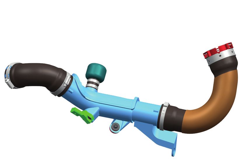
Indirect intercooling integrated in the intake manifold:
Indirect intercooling: Air-water cooler Integrated air-water cooler
Here, cooling is performed using a cooler with water flowing through it. The charge air Here, cooling is performed using a cooler integrated in the intake manifold with water
lines transport the medium over short distances. Since the cooler is typically perma- flowing through it. The cooler is permanently attached to the engine and integrated
nently attached to the engine here, the charge air lines only have to meet the instal- in the intake manifold here. The charge air lines transport the medium over short
lation tolerances and compensate for vibrations. There is no need to compensate for distances. There is no return line here.
the movement between the body and the engine with this system, as would otherwise
generally be required when using air-air cooling systems. Another advantage of this
Comparison with (direct) intercooling
In comparison with (direct) intercooling, indirect intercooling produces the following effects:
kind of system is the fact that the intercooling can generally be controlled via the + Significantly reduced drop in charge air pressure due to shorter distances
water cooler, which is not possible when using a direct system. + Improved engine dynamics thanks to a lower volume of charge air
+ Increased dynamic cooling capacity
+ Improved engine efficiency thanks to increased charge air density
– Increased cooling costs due to the need for an additional water cooling system
Fresh air
Air filter
Dirty air
Cooler pressure line (outward flow)
Fresh air
"Hot side"
Turbocharger
Air filter
Dirty air
Cooler pressure line (outward flow)
Engine "Hot side"
Turbocharger
Throttle
Exhaust gas valve
Throttle (Fitted to engine)
(Cooling water)
Engine
Water cooler
integrated in the intake
Exhaust gas
(Cooling water)
Water cooler
manifold
valve
Cooler pressure line (return flow)
"Cold side"
|7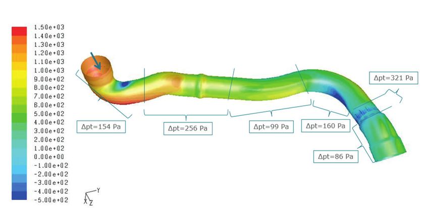
3. A typical charge air duct
The image shows an example of a charge air duct with potential fittings, as well as a
twopiece charge air pipe and two connected pressure hoses.
The plastic pipe is generally manufactured as a injection moulded or blow-moulded
part. When using the injection moulded version, it is often necessary to design the
plastic pipe as a multiple-piece unit for manufacturing reasons. The parts are then
welded together.
VDA coupling
The following welding processes can potentially be used here:
Charge air hose
• Infrared welding
• Vibration welding Resonator
• Hot gas welding
• Hot plate welding
Charge air pipe
Welded seam
Hose clamp
Charge air hose
Pressure-temperature sensor with anti-chafing
protection
8 | Veritas charge air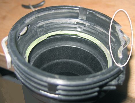
Requirements of materials (Veritas solutions) in the plastics product range
Temperature [°C]

                                                                                                         PPS
                                                                                                Temperature: Up to 215 °C
                                                                                           Short-term temperature: Up to 230 °C

                                                                                 PA4.6 GF30
                                                                                Temperature: 205 °C

                                                                                                         PPA
                                                                                           Temperature: 180 °C to 200 °C

                              PA6/66 GF30
                           Temperature: Up to 180 °C

                                                       PA66 GF30
                                                   Temperature: Up to 160 °C
                                                                               Based on:
                                                                                 • Pressure
                            PA6 GF30
                                                                                 • Chemical load e.g. exhaust gas recirculation
                       Temperature: Up to 140 °C
                                                                                 • Movement amplitude ± X mm

                                                                                                                                  Costs

                                                                                                                                          |9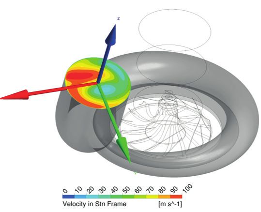
HT/HP
Layer sequence: FKM in line with DIN ISO 1629 GEN 7
MVQ
m-AR
MVQ
Requirements of materials (Veritas solutions) in the elastomer range of products Constant temp.: 230 °C
Short-term peak temp.: 250 °C
HT/HP
Layer sequence: FKM in line with DIN ISO 1629
HT
ACM 185 MVQ
Temperature [°C]
POD/m-AR
Layer sequence:
ACM MVQ
POD/m-AR
Constant temp.: 200 °C
AEM ACM
Short-term peak temp.: 230 °C
Classic
Constant temp.: 185 °C
Layer sequence: Short-term
AEM peak temp.: 200 °C
p-AR
AEM
Constant temp.: 160 °C
Short-term peak temp.: 180 °C
ACM
Alternative
Layer sequence: ACM
p-AR
ACM
Constant temp.: 150 °C
Short-term peak temp.: 170 °C
Barrier layer Pressure Outer layer
carrier
CM LT ECO
Layer sequence: CM
CR LT Classic
DT Layer sequence: ECO
Layer sequence:
CM CR p-AR
DT ECO
Constant temp.: 120 °C CR
Short-term peak temp.: 135 °C Constant temp.: 125 °C
Barrier layer Intermediate Pressure Top layer
Constant temp.: 110 °C Short-term peak temp.: 150 °C layer carrier
Short-term peak temp.: 125 °C
PC = Pressure carrier
Costs
10 | Veritas charge airInnovative connection technologies (Veritas solutions) The development stages of Veritas connections correspond to the increasing charge
Design: Veritas AG air pressures associated with boosted engine performance. With its "Vecoflan®"
coupling, including the accompanying hose connection, Veritas offers a connection
technology designed specifically for pressures up to 4.5 bar and temperatures up to
250 °C. Installation of the line is also much easier, as it can simply be slid into position
Pressure stage
from the side. The slide-in unit is secured using a secondary lock.
VECOFLAN®
VEBOCLIP®
Veritas safelock® "Click!"
Veritas TurboConnect®
Design developed for
up to 4.5 bar
VDA-compatible design Can be slid into position
from the side,
Snap-on compatible
with secondary lock
Cooler connection
Degree of innovation of connection
| 11Selection of typical charge air lines from Veritas' series production. 12 | Veritas charge air
4. Emissions legislation for passenger vehicles Tab. 1: Emissions legislation
2013 2014 2015 2016 2017 2018 2019 2020
For several years, there have essentially been four pieces of legislation, Czech Republic Euro 5 Euro 6
France Euro 5 Euro 6
various versions of which are applied in all emerging and industrial nations. Germany Euro 5 Euro 6
Hungary Euro 5 Euro 6
CARB legislation > California, similar limits apply in New York, Europe
Italy Euro 5 Euro 6
Poland Euro 5 Euro 6
Massachusetts, Connecticut, Vermont, Rhode Island, Maine and New Jersey Russia Euro 4 Euro 5
Slovakia Euro 5 Euro 6
EPA legislation > Rest of USA Turkey Euro 5 Euro 6
Great Britain Euro 5 Euro 6
Beijing Euro 5
EU legislation China China Euro 4 Euro 5
Taiwan Euro 5
Japan Japan ´09
Japanese legislation Japan/Korea
South Korea Euro 5 Euro 6
Middle East/ Iran Euro 2
Africa
The following table shows the binding laws and their entry into force worldwide. South Africa Euro 4
Canada Tier II, Bin 4 Tier II, Bin 2
North Mexico - petrol Euro 4 Euro 5
America USA Tier II, Bin 4 Tier II, Bin 2
USA California LEV III
Argentina Euro 5
South
Brazil - LCV diesel Euro 5 Euro 6
America
Brazil - petrol Euro 5 Euro 6
Australia Euro 4
India - metropolitan region Euro 4
India - rest Euro 3
South Asia
Indonesia Euro 4
Malaysia Euro 3
Thailand Euro 4
| 13LP EGR (low-pressure exhaust gas recirculation)
Technologies are being further refined and improved to comply with the emission The composition of LP EGR condensate always varies and depends on the following
limits. Exhaust gas recirculation (EGR) is an important technology in this regard. factors:
• Engine performance and engine management
The principle is based on feeding exhaust gas into the combustion chamber as a way • Driving style (speed, rpm, cold starts, etc.)
of reducing nitrogen oxides (NOX). When using LP EGR, the exhaust gas is fed back • Design of the cooling system
into the intake chamber by mixing in a portion of the fresh air intake via a pipe. • Composition of the fuel (S, H2O, RME, etc.)
With diesel engines, it is one of the most important ways to reduce nitrogen emissions.
Depending on the air/fuel mixture and driving profile, the condensate can contain a
large volume of organic or aggressive acids.
However, this technology places strict requirements on the resistance of the materials
used for the charge air ducts. Depending on the concentration, the medium can
contain a high percentage of acid and have a pH value of less then 1. If the incorrect
material is then selected, the plastic or elastomer hoses of the charge air lines can
be directly damaged. This can ultimately lead to system failure.
Veritas offers the right solutions for charge air ducts, which fulfil the requirements of
high material resistance to the acidic medium throughout their service life.
EGR: A complex, variable and aggressive mix (with a pH value below 1)
14 | Veritas charge air5. Simulation and testing
Current and future requirements Simulation and testing
Higher charge air pressures lead to higher temperatures. Temperatures of up to From the first design stage to the series production product
250 °C are possible using Veritas silicone hoses. Since silicone hoses are comparably
expensive, efforts are being made to use new types of plastic materials for a large
CAD and simulation
proportion of the charge air duct. At the same time, the materials must offer greater
resistance, particularly against aggressive media such as the
EGR condensate already mentioned.
Further research and development work is required in order to meet all of these
requirements. Measuring technology
Ever stricter requirements also require new and more extensive testing. The scope
and costs of meeting testing requirements are also increasing for OEMs and system
suppliers as a result of this. The trend here is to shift responsibility for the tests to
the system supplier.
Materials testing
After all, system suppliers boast comprehensive knowledge of materials, component
design and simulation, as well as an excellent understanding of systems.
To give you an idea of what is being referred to here, the following pages list several
tools for system design, simulation and testing, as well as the extensive testing Function testing
equipment of Veritas AG required to perform the charge air duct tests.
| 15Computational fluid dynamics (CFD) Static pressure at pipe wall Speed distribution flow lines
The example shown here is a pressure loss calculation for a charge air line.
Pressure drops are unavoidable due to the path traced by the line, which can only be
adjusted slightly due to the conditions of the installation space. It is therefore important
to detect and subsequently eliminate the pressure losses while the project is still in
the development phase.
Total pressure loss: 1076 [Pa]
1.076 kPa / 10.76 hPA /
10.76 mbar / 0.01076 bar
Swirling inflow
16 | Veritas charge airNumerical structure calculation
Computer-assisted numerical process for calculations: Finite element method (FEM)
The strength calculation of a quick release coupling is shown here as an example.
The connection elements of charge air ducts are subjected to special pulse-based
component loads in the form of pressure and temperature influences. Calculating
the mechanical load allows complex material behaviour and non-linear stress-strain
relationships to be presented and the components therefore optimised.
Structure calculation Component failure in the area of a clamping bracket
| 17Tests
During the development phase, comprehensive tests are to be performed on the Burst pressure test bench
charge air system to secure proper functionality of all components throughout the For pressures up to 1000 bar, test medium = water
entire life cycle. The tests represent the life cycle (time-lapsed). The test requirements
are the result of customer requirements (works standards and requirements
specifications). Loads take the form of temperature changes, pressure changes
and three-dimensional movements, which are generally applied in combination.
Temperature change test bench with shaker
Temperature unit with electrodynamic shaker, chamber volume of 1000
Overview of testing options at Veritas AG litres, chamber temperature from -70 °C to +180 °C, pressure up to 15 bar,
vibration amplitude +/- 25.6 mm, frequency from 5 Hz to 3000 Hz,
Pulse test bench with temperature control for the medium and the max. acceleration 60 g
chamber, as well as a rotation and buckling unit
Four large-scale test benches for bithermal charge air testing, three of which CT test bench
are equipped with a multi-axial movement unit and/or vibration excitement, Computer tomograph for measuring parts and non-destructive component
ambient temperature of -40 °C to +220 °C, medium temperature from Rt to testing
300 °C, pressure up to 4 bar
Pulse test bench with chamber temperature control
Thirteen test benches for unithermal charge air testing, temperature range
from Rt to 300 °C, pressure up to 15 bar
Salt-spray mist chamber for corrosion testing
Chamber volume of 1000 litres, NaCI solution medium, relative humidity from 10% to 95%
Chamber temperature from Rt to 60 °C, medium temperature from Rt to 75 °C
Pulse test bench with movement unit at RT
Pressure range from 0.1 bar to 15 bar, air test medium, movement Acoustic measurements
distance: ± 50 mm, force up to 5 kN, frequency up to 200 Hz
18 | Veritas charge air6. Outlook
The proportion of vehicles fitted with turbocharged engines is on the rise worldwide Increasingly stricter vehicle emissions legislation is leading to higher requirements in
and continuing to gain ground on vehicles with naturally aspirated engines. Indeed, terms of pressure, temperature and material resistance. The concepts of downsizing/
around 55% of all engines are expected to be employ some form of boosting by 2023. rightsizing are motivating many manufacturers to produce smaller or optimised
The market for charge air ducts therefore remains promising. engines. The performance of these models is boosted by employing higher charge
(Source: IHS) air pressure, which in turn leads to higher temperatures.
This development process is continuous and there is currently no physical limit in sight.
Charge air pressures of up to 4 bar are already in development for passenger vehicles.
Number of boosted engines worldwide by 2023 (in millions) Emission limits only achievable with boost systems
• Higher pressures
45 • Higher temperatures
42 43
40 • Downsizing/rightsizing
38
35
32 Increasing pressure requirements largely 4 bar
EU1 correlate with the tightening of emission limits and
29
more
Pressure requirements
Emission limits EU2
EU3
EU4
EU5 EU6
2016 2017 2018 2019 2020 2021 2022 2023 1992 1996 2000 2005 2009 2014
| 19Veritas AG Stettiner Straße 1-9 63571 Gelnhausen Germany Tel: +49 (0) 6051 821-0 Fax: +49 (0) 6051 821-1900 veritas@veritas.ag www.veritas.ag
You can also read