The New Delphi Injector Family - Architecture and Performance
←
→
Page content transcription
If your browser does not render page correctly, please read the page content below

The New Delphi Injector Family –
            Architecture and Performance

            Peter Voigt, Jean-Luc Beduneau, Noureddine Guerrassi,
            Hans-Josef Schiffgens

                                                                                                    17
© Springer Fachmedien Wiesbaden 2015
H. Tschöke (Hrsg.), 9. Tagung Diesel- und Benzindirekteinspritzung 2014, Proceedings, DOI 10.1007/978-3-658-07650-4_2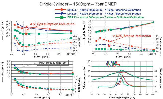
The New Delphi Injector Family – Architecture and Performance

Abstract
Car manufacturers around the world are facing the significant market challenges of
meeting strict governmental emissions regulations and fuel economy standards while
delivering the performance that consumers demand. Building on the successes already
achieved and the extensive experience in the global market, Delphi continues
to develop next-generation technologies to meet these demands, including a new
family of injectors, fuel pumps, Engine Control Units (ECU) and rails for light- and
medium-duty applications to better fit customer requirements.
This new family of fuel injection equipment (FIE) offers improved performance
through increased multiple injection optimization, leakage reduction and injection
pressure increase up to 2,500 bar, translating into better injection control and better
combustion, thus reducing fuel consumption, CO2 and other emissions.
This paper focuses on new Diesel injectors. It describes briefly the approach Delphi
utilized to develop this family composed of three injectors (DFI1.20, DFI1.22 and
DFI4.25) and outlines the innovative features included in it. The modular approach of
the new Delphi injector family is also shown in a ‘strength-diagram’, where cost and
technical performance are rated. A more complete analysis is done on capability of-
fered by the DFI4 injector in terms of combustion strategy. The new performances of
the DFI4 allow the utilization of new combustion modes linked to rate shaping due to
its very good injection control and stability.
Keywords: Common Rail, Fuel Injection Equipment, Diesel, High Pressure, Injector

18
The New Delphi Injector Family – Architecture and Performance
1 Market requirements for next generation systems
Diesel engines have been popular since the beginning of the engine industry because
of their remarkable fuel efficiency. This best-in-class fuel economy will continue to
be in high demand in European and other markets, driven by continuous development
on all types of engines and by unprecedented thrust towards lower CO2 fleet averages
(Fig.1). This will require fuel injection equipment to provide better injection rate,
flexibility and accuracy to promote best combustion. In addition, it should also mini-
mize all types of losses taking place in the system: pressure drop, unwanted leakage
and cooling flows, and all types of electrical consumption.
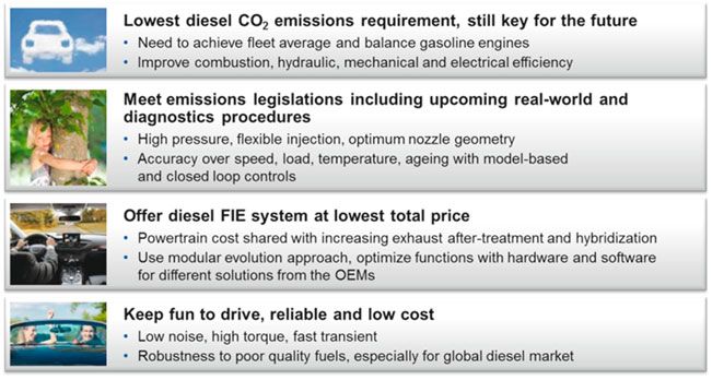
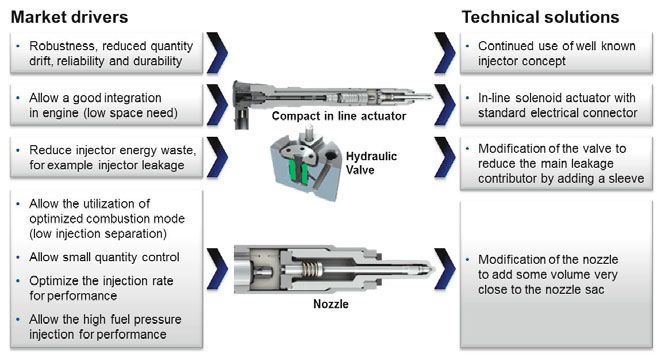
Fig. 1: Main market requirements for next generation Passenger Car & Light Commercial
Vehicle Common Rail Systems
The next key requirement is the lowest possible cost for the diesel FIE system. For
high efficiency, emissions and refinement, the complexity of powertrain and exhaust
after treatment systems is rising rapidly, with strict limits on what the end customer is
prepared to pay. Delivering complex systems at a price the market will accept will be
achieved with a simple base design that retains modular features enabling high-
volume reuses. The base hardware design will be complimented by sophisticated con-
trols on injection, pressure and diagnostics to reach full functionality.
Needless to say, the injection system must contribute to fulfil all mandatory emission
legislations, including real-world driving emissions and diagnostics. Key attributes are
higher maximum pressure with efficient rate, optimized nozzle design and flexible
19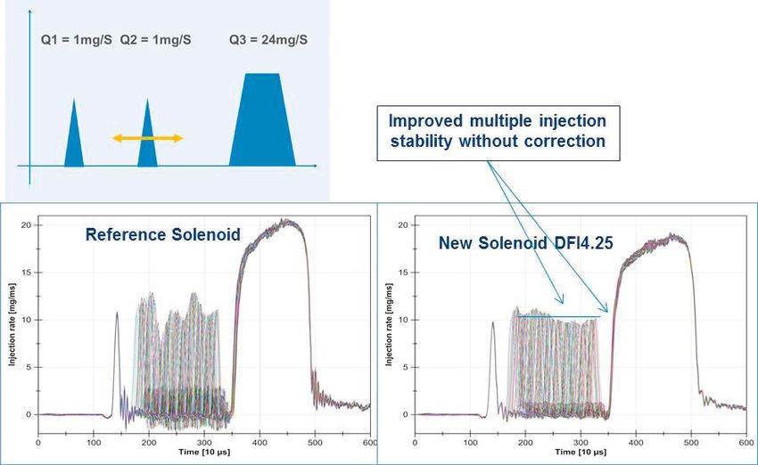
The New Delphi Injector Family – Architecture and Performance

multiple injection pattern. The needed injection quantity and timing will be maintained
over speed, load, temperature and aging, as well as part-to-part variation through mod-
el-based and closed-loop controls. Finally, for the end user to continue buying diesel
powered vehicles, they must continue to be fun to drive, thanks to high torque at low
engine speed and controlled noise. Additionally, the traditional reliability and low cost
of ownership, resulting in very high resale value for diesel-powered cars, is expected to
counterbalance the higher initial price compared to some other powertrains.

2 New solenoid injector family with a focus
  on DFI4 features
Delphi solenoid injectors are well known and present in all markets around the world
with among the best value light-duty diesel Common Rail system in the industry.
Leveraging its expertise in this field, Delphi developed a new solenoid family to help
OEMs meet new regulations and market challenges. The solenoid technology has
been identified as the most efficient to reach the target cost set by the market to main-
tain Diesel technology competitiveness. It is also a robust technology that can be used
for high mileage applications without any actuator aging.
Many requirements are to be considered when developing a new injector family. But
the most important one is to maintain the best cost/quality ratio, to help OEMs meet
the markets’ needs.
Considering the needs and Delphi’s strong experience in solenoid common rail injec-
tor technology, the current DFI 1.5 injector has been used as a basis for the develop-
ment of the new family of injectors. This decision is supported by customer feedback
describing the DFI 1.5 injector as a very good design with a strong potential remain-
ing in the concept.
The decision to develop a family of injectors rather than just one injector is driven by
the necessity for light-duty injectors to meet not only one market and one type of ve-
hicle but also different applications with a worldwide and diverse segment approach-
es. To answer this challenge a modular approach was developed. This approach con-
sists of having a single injector outline with different features available inside helping
the OEM to select the appropriate content depending of the engine and vehicle need.
Another advantage of using the DFI 1.5 injector as a basis for a new family of injectors
is the ability to leverage the feedback from the field to ensure a very high quality level at
the start of production; a critical element for a flawless launch and production ramp up.
The new solenoid injector family is composed of three injectors that address all re-
quirements to answer current and future market needs (Fig. 2).

20
The New Delphi Injector Family – Architecture and Performance
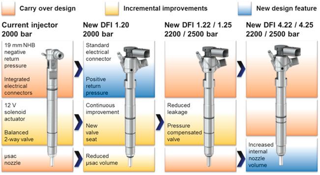
Fig. 2: Market drivers for the development of the new injectors
The three new injectors (DFI 1.20, DFI 1.22/25 and DFI 4.22/25) offer a rising level
of performance available for targeted vehicle segments and regions (see Fig. 3). Fea-
ture adjustments are done in different areas. The injection pressure is one of the key
parameters and is commonly seen as a key driver for high performance, helping also
to balance the trade-off between the pollutant emission reduction at source and some
after treatment features utilization.
Several important features were improved, such as injector leakage that was addressed
by a smart and integrated solution (Sleeve Valve Adaptor-plate), or the injection sepa-
ration, with volume added in the nozzle, very close to the sac and the injection holes.
21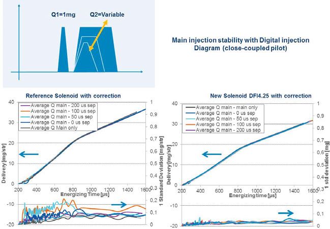
The New Delphi Injector Family – Architecture and Performance

Fig. 3: Delphi Solenoid injector family

The basis of the new solenoid injector family is the DFI 1.5 injector. This injector has
a very good performance and the concept presents significant potential in line with
market requirements. Indeed, thanks to downsizing the valve equilibrium is possible
to maintain at high pressure without drastic change of the concept. Figure 4 shows the
equilibrium obtained for two dimensions and two pressures. With the reduced dimen-
sions, the force applied on the valve is equivalent to the one utilized today on the
DFI 1.5 injector. Based on this small modification the DFI1.5 capability is extended
to pressure up to 2500 bar. And, using the downsizing approach, the rail pressure limi-
tation with the current solenoid is around 3400 bar with a 1mm stem, resulting in a
robust, proven injector that is based on years of injector design. Delphi has the manu-
facturing capability to downsize and does not see a need to increase the solenoid size
or to change the basic architecture.

22
The New Delphi Injector Family – Architecture and Performance

Fig. 4: Impact of the downsizing on forces applied to the valve regarding the pressure

For upgrading this injector, customer comments and feedback from the development
phases and the field were also taken into account to allow production of a robust and
effective injector that is well adapted to the latest engine generations.

Fig. 5: Cost to value diagram for the Delphi injectors

                                                                                         23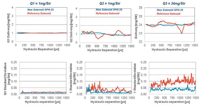
The New Delphi Injector Family – Architecture and Performance

Figure 5 presents a cost-versus-performance comparison for the Delphi solenoid in-
jector family. By applying a certain weight to main injector features as injection rate,
maximum rail pressure, control leakage etc. a technical value can be associated to
each injector. The dashed lines represent lines of constant market value which is as-
sumed to be proportional to the quotient cost / technical value.
The diagram shows that Delphi is able to provide numerous variants with one base
concept that provide different levels of technical value. Of course, additional features
increase the cost. However, Delphi ensures that all chosen configurations perform at
high market value.
The DFI4 injector presents a very high rating very close to servo piezo-injectors. The
capability to utilize solenoid technology at high rail pressure is a very powerful solu-
tion for a competitive cost which is a critical parameter to meet the challenge of Die-
sel engine cost control in the future.
The DFI 4, which is the latest injector within this Delphi solenoid injector family, was
developed to offer 2,500 bar to OEMs for premium engine performance or to mini-
mize the utilization of costly after treatment.
One of the first improvements on the DFI4 injector is a drastic reduction of static
leakage. This reduction is obtained due to a smart feature consisting to the insertion of
a sleeve in the Combined Valve Adaptor-plate (CVA) (Fig. 6) from the DFI1.5 injec-
tor leading to a Sleeve Valve Adaptor-plate (SVA). The purpose of this sleeve is to
obtain a very small deformation when the pressure increases leading to a gap reduc-
tion between the sleeve and the stem. Due to this, the static leakage is very small and
insensitive to the pressure. This leakage reduction allows reducing the back leak tem-
perature and thereby permitting a running mode at high pressure, 2500bar. Thanks to
this feature, the power dissipated at the back leak at 2500 bar with a DFI4 injector is
lower than a DFI1.5 injector at 1800bar.

24
The New Delphi Injector Family – Architecture and Performance
Fig. 6: Difference between CVA and SVA
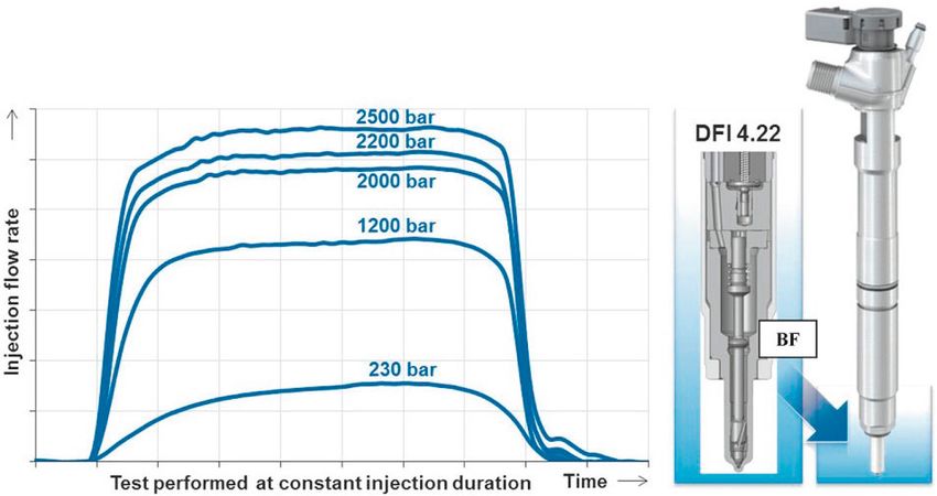
The high performance is obtained thanks an important volume added as closely as
possible to the injection holes (Fig. 7). This was done in addition to reducing the
throttling characteristics within the injector high pressure feed to the nozzle.
Those features were obtained by modifying the injector nozzle with the same actuator
and hydraulic control valve as the DFI 1.22. The volume is located as close as possi-
ble to the injection hole to benefit the high pressure fuel during injection, resulting in
a high squareness of the injection rate in single event and damping of the pressure
waves during a multiple injection, especially in close events.
As observed on the injection rate (Fig. 7), the addition of the volume and the reduc-
tion of the throttling allowed the injector to obtain square and very high maximum
injection rates. The injection rates obtained with the DFI 4 injector is directly com-
parable to those obtained with direct acting piezo-electric technologies. The throt-
tling reduction is obtained due to a feature referred to as “Boost Flange” (BF on
Fig. 7). The BF generates a very small pressure difference above and below the
boost flange, thanks to its surface, this small pressure difference is enough to help
the needle closure. A rapid needle closure, as observed on the injection rate, is im-
portant to minimize the emission impact linked to the injection pressure reduction
during the needle closure.
25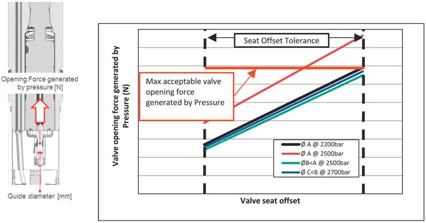
The New Delphi Injector Family – Architecture and Performance

The results obtained with the DFI 4 reinforce the choice of the solenoid technology
for injectors up to 2,500 bar. The performance is obtained by the addition of a fully
optimized hydraulic coupling with a very effective nozzle.

Fig. 7: DFI 4 injector with very high performance output

On the DFI4 injector, as on the complete solenoid family starting with DFI 1.20, the
nozzle detailed geometry was re-examined and optimized, so that the sac volume
could be further reduced. The amount of sac volume reduction varies around 10%,
depending on the nozzle needle tip shape used according to the nozzle flow.

26
The New Delphi Injector Family – Architecture and Performance

Fig. 8: New sac geometry with minimized dead volume combustion benefits
(DFI 1.20 vs. DFI 1.5 injector)

As anticipated, the sac volume reduction, when tested in a back to back comparison
with the previous design, brings a reduction in HC emissions from 7% to 50% and
CO emissions from 8% to 20% (Fig. 8). The amount of this reduction depends of
the operating point speed and load settings. Any reduction in sac volume is needed
to help meet tighter emissions in cold phases without excessive precious metal cata-
lyst load.
On the DFI 4 injector, as explained in the previous section, a high pressure volume
close to the nozzle has been installed with the aim of improving injection rate effi-
ciency, as already shown. Thanks to this improved hydraulic stability the multiple in-
jections behaviour is also improved. Indeed, the perturbation initiated by one injection
and affecting the next one on the same injection train will be minimized; particularly
in the case of close injections events. The curves below, measured on a system rig,
demonstrate how the quantity deviation is reduced and that the pilot injection leads to
much less perturbation of the main injection. This enables more accurate results once
software compensation functions are applied.

Digital injection diagram
The main injection system evolution considered by Delphi to fulfil future market and
regulatory requirements concerns the injection pressure increase coupled with injector
nozzle hole reduction (currently respectively 2000 bar and 100μm). This evolution will

                                                                                     27
The New Delphi Injector Family – Architecture and Performance allow better fuel air mixing, combustion efficiency improvement and potential power density upgrade. The enhancement of power density will allow engine downsizing and thus consumption and CO2 emission reductions. The new family of diesel fuel injection equipment offers improved performance through injection pressure increased up to 2500 bar; leakage reduction; and increased multiple injection flexibility, as the fuel in- jectors will be capable of up to nine injections per cycle. Recently, several research pro- jects show the requirement to extend the multiple injection capability for closer injection calibrations with very small hydraulic separation called “Digital Injection Diagram”. This new calibration diagram will require new engine parameter tuning to reach further emissions and NVH improvement with the common rail systems. In addition to the in- jection pressure increase, the new Delphi solenoid DFI4.25 includes several features like integrated mini-rail volume close to the nozzle seat and improved valve in order to match the new combustion requirement for Digital Injection Diagram. Fig. 9: Injection rate stability measured on test rig at different hydraulic separations with the new solenoid DFI4.25 The requirement of increased flexibility of multiple injections includes an increase in the number of injections combined with very small separations. Figure 9 shows an injection pattern with three injection events but with a varying temporal posi- tion of the second injection event. The injection rate stability of the new DFI4.25 solenoid can be compared to a reference solenoid, and shows much more stable in- jections even with very small separations below 100μs and without any software 28
The New Delphi Injector Family – Architecture and Performance

correction. This improvement results from design changes which minimize the hy-
draulic wave amplitudes within the HP pipes and inside the injector.

Fig. 10: Multiple injection stability measured on test rig at different hydraulic separations with
the new solenoid DFI4.25

Figure 9 shows the delivery curve with software correction when using a digital injec-
tion diagram with a hydraulic separation which varies between 0 and 200μs. These
tests are carried out using a fixed quantity on the first injection event and by varying
the energising time of the second injection event. Both the new DFI4.25 and the refer-
ence injector have delivery curves for the second injection event which have the same
form regardless of the hydraulic separations. However, DFI4.25 show significantly
better robustness of injection quantity control as seen in the low shot-to-shot standard
deviation values.
These hydraulic performance tests show the ability of the new solenoid injector de-
sign to reach future performance targets necessary for digital injection diagrams.
Figure 10 shows the resulting fuel quantities and shot-to-shot standard deviation for
the same multiple injection diagram as on Figure 9. A perturbation is initiated by the
first injection event and affects the subsequent events on the same injection train. This
perturbation must be minimized for good combustion performance, particularly in the
case of pilot-to-pilot or pilot-to-main interaction. As shown in this figure, the shot-to-
shot standard deviation is also very low on DFI4.25 due to the improvement of the
nozzle and the valve design.

                                                                                                 29
The New Delphi Injector Family – Architecture and Performance Fig. 11: Main injection variation for close injections measured on test rig with the new solenoid DFI4.25 Benefit of injection pressure increase The use of increased pressure for emission reduction or power density increase is explained in Figure 12. The diagram shows the relationship between the required en- gine power density and the nozzle flow definition on small engine capacity, for dif- ferent maximum common rail pressures. For the constant power density requirement (blue arrow), there is a potential for the injector nozzle flow to be reduced when the maximum rail pressure increases. This nozzle flow reduction is achieved through nozzle hole size reduction, leading to significant emission, combustion noise and fuel consumption reductions. Experimental engine tests were carried out on generic single cylinder engine in order to quantify the potential benefits at full load and on emission modes. 30
The New Delphi Injector Family – Architecture and Performance

Fig. 12 : Power density evolution with injector nozzle flow
(Single Cylinder Engine tests at 4000rpm – Full load)

The use of higher rail pressure allows the nozzle hydraulic flow to be reduced for the
same peak power target. This reduction of the nozzle hole size allows significant ben-
efits in emissions at low load modes as shown in Figure 13. Without modifying the
calibrations, such as rail pressure and EGR ratio, the lower nozzle flow gives a direct
benefit in smoke emissions (-50%) and combustion noise (-3db). Such low noise lev-
els allow a recalibration of the injection parameters to higher rail pressures or for a re-
duced number of pilot injections. By adapting the calibration with the same reference
combustion noise, a significant reduction in the smoke vs. NOx trade-off was
achieved. Depending of what EGR level that is used in the engine calibration, im-
provements of more than 60% in smoke and 4% on specific consumption are possible,
whilst maintaining constant in HC, CO and noise.

                                                                                        31
The New Delphi Injector Family – Architecture and Performance
Fig. 13: Emission benefit with injector nozzle flow reduction
from 500ml/min to 360ml/min at low load
Conclusion
The new Delphi injector family provides major improvement in three key areas:
Leakage
Injection pressure
Digital rate shaping capability
Further improvement of solenoid injectors are possible using the capability of further
valve downsizing.
32You can also read