Novel Architecture for Efficient Implementation of Dimmable VPPM in VLC Lightings
←
→
Page content transcription
If your browser does not render page correctly, please read the page content below
Novel Architecture for Efficient Implementation of
            Dimmable VPPM in VLC Lightings

              Jin-Doo Jeong, Sang-Kyu Lim, Il-Soon Jang, Myung-Soon Kim, Tae-Gyu Kang, and Jong-wha Chong

  In this paper, a new architecture is proposed to achieve                                      I. Introduction
complexity efficiency in implementing variable pulse
position modulation (VPPM). VPPM, specified in IEEE                                                Variable pulse position modulation (VPPM) is a modulation
802.15.7, can support wireless communication and                                                scheme proposed for visible light communication (VLC). VLC
dimming control simultaneously using visible light. The                                         systems carry out data communication through a wireless
proposed architecture is based on the VPPM signal                                               optical channel using visible light modulated in LED
property in which the transition point of the modulated                                         luminaires capable of obtaining high-speed switching [1]–[5].
output is obtained by counting the sample index and                                                In general, many applications using LED luminaires require
comparing it to both the assigned dimming factor and the                                        dimming controllability to adjust the illumination intensity for
transmitting data. Therefore, the proposed architecture                                         context awareness or to reduce the power consumption for
can be composed of simple logics, including a counter, a                                        energy saving, and dimming is an essential function of modern
comparator, and an inverter, all of which are insensitive to                                    VLC systems [6]–[10].
the dimming resolution in contrast to a conventional                                               VPPM is one of the modulation schemes internationally
codeword-table method. This paper describes the                                                 standardized to obtain both wireless communications and
verification of the proposed algorithm through a register-                                      brightness control simultaneously through the LED luminaires
transfer level implementation of the codeword and                                               described in [1] and [2]. Studies on VPPM have been
proposed architectures. In comparison with the codeword-                                        performed in such fields as an analysis of modulation signals
table method, the proposed method gains a nine-fold                                             [3] and the presentation of a receiving method [7]–[8].
complexity reduction at a 1% dimming-step resolution.                                           However, implementation issues considering hardware
                                                                                                complexity have been little studied.
   Keywords: Dimming, VLC, VPPM, LED, RTL.                                                         In this paper, a design architecture is proposed to achieve
                                                                                                complexity efficiency in implementing the VPPM systems.
                                                                                                From the existing study in [3], tabling the codewords can be
                                                                                                considered as the design scheme. However, the codeword-table
                                                                                                method can increase the complexity with an increase in
                                                                                                dimming-control resolution. The proposed design can obtain
   Manuscript received Mar. 31, 2014; revised July 10, 2014; accepted July 17, 2014.
   This work was supported by the MOTIE KEIT (10042947, System Lighting), the MSIP              implementation efficiency insensitive to the dimming
IITP (10040037, Intelligent IT Lighting), and the ICT Standardization Program of MSIP, Rep.     resolution and is appropriate for VLC applications requiring
of Korea.
                                                                                                highly resoluble dimming.
   Jin-Doo Jeong (corresponding author, jdjeong@etri.re.kr), Sang-Kyu Lim (sklim@etri.re.kr),
Il-Soon Jang (isjang@etri.re.kr), Myung-Soon Kim (mskim75@etri.re.kr), and Tae-Gyu Kang
(tgkang@etri.re.kr) are with the IT Convergence Technology Research Laboratory, ETRI,
Daejeon, Rep. of Korea.
                                                                                                II. VPPM Modulation Based on Codeword Table
   Jong-wha Chong (jchong@hanyang.ac.kr) is with the School of Electrical and Electronics
Engineering, Hanyang University, Seoul, Rep. of Korea.                                            The VPPM modulation scheme basically makes use of the

ETRI Journal, Volume 36, Number 6, December 2014                                      © 2014                                         Jin-Doo Jeong et al.   905
http://dx.doi.org/10.4218/etrij.14.0114.0396
Brightness Sample_Clock
Symbol_Clock
DTX = 0 DTX = 0 DTX = 1
Tx_Data
30% Dimming_Level
Codeword table for bit 0
50% 0000...0000 0
1000...0000 1
1100...0000 2
…
…
…
1111...1100 M–2
70% 1111...1110 M–1
t 1111...1111 M
Mux 0
T = NTTS 3T Parallel
TD = γT = γNTTS T–TD = (1–γ)T = (1–γ)NTTS Z–1
Codeword table for bit 1 to serial
1
(where T is symbol duration, TD is pulse duration for dimming control, γ is dimming Register VPPM_
0000...0000 0 Mux
factor, TS is sampling period, and NT is codeword-length per VPPM symbol) 0000...0001 1 Mod_Signal
0000...0011 2
…
…
…
Fig. 1. Signal waveform of VPPM. 0011...1111 M–2
0111...1111 M–1
1111...1111 M
Mux
Table 1. Codewords for VPPM with 10% dimming step. Fig. 2. Typical block diagram of table-based VPPM modulation.
Dimming factor γ Codeword for Bit 0 Codeword for Bit 1
0 0000000000 0000000000 to reduce the hardware complexity owing to a large codeword
table [11]–[12]. No studies on the design or implementation of
0.1 1000000000 0000000001
dimmable VPPM modulation based a codeword table such as
0.2 1100000000 0000000011
Table 1 have been performed. This paper proposes a design
0.3 1110000000 0000000111
method for VPPM modulation based on a discrete logic
0.4 1111000000 0000001111 architecture to obtain a lower complexity than that of the
0.5 1111100000 0000011111 typical table-based design.
0.6 1111110000 0000111111 Figure 2 shows a typical block diagram of table-based
0.7 1111111000 0001111111 VPPM modulation by applying codewords in Table 1 to
0.8 1111111100 0011111111 the codeword-table structure in [12]. In Fig. 2, Tx_Data,
0.9 1111111110 0111111111
Dimming_Level, and VPPM_Mod_signal indicate the data to
be delivered, the dimming index closely linked to the dimming
1.0 1111111111 1111111111
factor (γ), and the synchronized (or synthesized) VPPM-
modulated output signal, respectively. From Fig. 2, it can be
supposed that the hardware complexity of the table-based
main characteristics of 2-pulse-position modulation (2-PPM) VPPM modulator increases with an increase in the dimming
for data transmission together with pulse-width modulation resolution. Therefore, this paper proposes and describes a new
(PWM) for dimming control [1]–[3]. Figure 1 shows a signal architecture composed of only simple digital logics to avoid an
waveform of VPPM based on a combination of 2-PPM and increase in hardware complexity even when the dimming
PWM. The VPPM signals can be expressed in the digital resolution increases.
domain using a memorized mapping table, as shown in Table 1,
where the codewords for the VPPM, with a 10% dimming III. Proposed Architecture for Complexity Efficiency
resolution, are listed. In Table 1, γ indicates the dimming factor,
which indicates the relative brightness level, within a range of The architecture design for mitigating the hardware
zero and one. The VLC data are not transmitted when the complexity of functional blocks for VPPM begins with the
dimming factor is zero or one because they represent cases in modeling on VPPM-modulated signals, as expressed in (1).
which the VLC luminaire is in a “fully off” or “fully on” state, ∞
respectively. Figure 1 also shows the signal waveforms, which s (t ) = A∑ pVPPM (t − nT ),
n =0
illustrate the VPPM dimming mechanism (dependent upon the
⎧ T ⎡δ ( t ) − δ ( t − γ T ) ⎤ dt for D = 0, (1)
dimming factors listed in Table 1). ⎪ ∫0 ⎣ ⎦ TX
pVPPM (t ) 0≤ t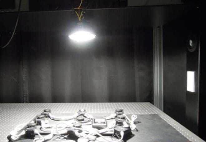
delta function, symbol duration, and transmitting data,                                                Counter
respectively. Equation (1) shows that a modulated signal can be               Sample_Clock       Count-up      Count                 ns
characterized by DTX and the transition point from low to high                Symbol_Clock       Reset         value
                                                                                                                                                Comparator
or high to low within the symbol duration.                                                                                                  ≥
                                                                                 DTX

                       ⎧1    for DTX = 0 and 0 ≤ t < γ T ,                        ND                                       0
                                                                                                                                NTP
                       ⎪0    for DTX = 0 and γ T ≤ t < T ,
                       ⎪                                                                              –
 pVPPM (t ) 0 ≤t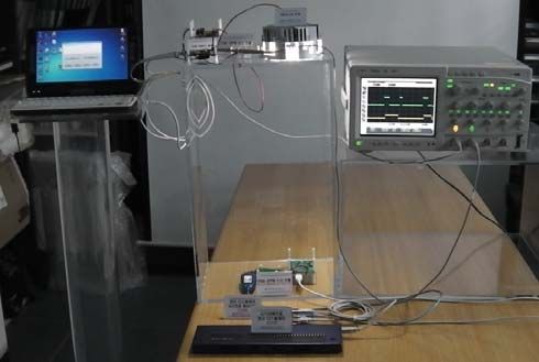
through a comparison result between ns and NTP. Next, ns is
increased for each of the following sample indices; that is, ns + 1.   Table 2. Complexity comparison results between the codeword-table
                                                                                method and proposed method.
   The proposed architecture in Fig. 3 is composed of
relatively simple logics including a counter, 2 × 1 comparator,                                  Cell usage in XC3S500e FPGA
                                                                       Dimming step (%)
subtracter, inverter, and two 2 × 1 muxes. Therefore, the                                 Codeword-table method     Proposed method
                                                                       (codeword length,
complexity increase of the proposed modulator is slight                  resolution bits)             FlipFlops              FlipFlops
                                                                                           BELS                    BELS
compared with a table-based modulator. This means that the                                             /Latches               /Latches
proposed method is more efficient in implementing a VPPM                   33.33 (3, 2)             12             10      12         10
transmitter.                                                                 20 (5, 3)              17             12      15         12
                                                                            10 (10, 4)              33             14      22         14
IV. Implementation and Experimentation Results                               5 (20, 5)              76             16      26         16

   For a complexity comparison, the table-based method and                 3.33 (30, 5)            131             16      26         16

the proposed method were designed at the register-transfer                  2.5 (40, 6)            142             18      29         18
level (RTL) using a hardware description language. For the                   2 (50, 6)             187             18      29         18
design verification, it was determined whether the input and               1.25 (80, 7)            274             20      35         20
output signals in the proposed method are the same as those                 1 (100, 7)             325             20      35         20
in the codeword-table method. Figure 5 shows the timing                                         Cell usage in CoolRunner2 CPLD
simulation results in both the table-based and the proposed            Dimming step (%)
                                                                                          Codeword-table method      Proposed method
method with a 10% dimming-step resolution using the                    (codeword length,
                                                                         resolution bits)             FlipFlops               FlipFlops
ModelSim tool [13]–[14]. This means that the waveforms of                                  BELS                     BELS
                                                                                                       /Latches                /Latches
the proposed method are equal to those of the table-based                  33.33 (3, 2)             36             10      23         10
method, and the required power and spectral efficiencies of
                                                                             20 (5, 3)              60             12      34         12
both methods are equal to the results in [3]. In Fig. 5, the pulse
                                                                            10 (10, 4)             105             14      55         14
width of the modulated signal is changed according to the
dimming-level input, the full brightness of which is 10. The                 5 (20, 5)             119             16      69         16
VPPM modulation was also verified by monitoring the                        3.33 (30, 5)            198             16      67         16
detected data of the VPPM demodulator with a loopback input                 2.5 (40, 6)            183             18      83         18
from the modulator, which was designed using the table-based                 2 (50, 6)             487             18      82         18
method or the proposed method.                                             1.25 (80, 7)            702             20      97         20
   Table 2 shows the complexity comparison results between                  1 (100, 7)             851             20      96         20
the codeword-table method and proposed method. The
                                                                        (BELS represents basic elements in FPGA or CPLD)

  In/out signals of
 VPPM modulator           Sample clock
 dk                   1
                                                                       comparison results were derived from the synthesis of the RTL
                          Enable to modulator
 mod_en               0                                                designs of a Xilinx XC3S500e FPGA and CoolRunner2
                          Symbol clock                                 CPLD using the ISE tool [13], [15], with a synthesis option
 mod_sdk              0
                                                                       for area optimization. In Table 2, a 33.33% dimming step
                          Transmission input data
 mod_in_data          0                                                represents the maximum step supporting dimmable VLC
 dimming_level 0
                                                                       transmission. The complexity of the codeword-table method
                                                                       increases as the dimming resolution increases, as shown in
                          Dimming level
 dimming_level 0                                                       Table 2. On the other hand, the complexity of the proposed
                          VPPM modulated signal
                                                                       method is only slightly increased. At a 1% dimming-step
 mod_out_signal 0
                                                                       resolution, the proposed method gains a complexity reduction
 In/out signals of
VPPM demodulator          Loopback signal to demodulator               by about nine-fold compared with the table-based method. This
 demod_in_signal 0
                                                                       means that the implementation efficiency is achieved using the
                          Detected data
 demod_out_data 0                                                      proposed method, especially at a high dimming resolution.
Fig. 5. Timing simulation results for both the table-based method         Table 3 shows the estimated power consumption results of
        and proposed method with a 10% dimming-step                    the codeword-table method and proposed method, which are
        resolution.                                                    obtained from a Xilinx XPower Analyzer with a 25 MHz

908            Jin-Doo Jeong et al.                                                      ETRI Journal, Volume 36, Number 6, December 2014
                                                                                                  http://dx.doi.org/10.4218/etrij.14.0114.0396
VPPM-Tx platform
Table 3. Estimated power consumption results of the codeword-table LED luminaire
method and proposed method. Oscilloscope
Dimming step (%) Estimated power consumption (mW)
(codeword length, Codeword-table method Proposed method
Computer
resolution bits) FPGA CPLD FPGA CPLD
33.33 (3, 2) 82.89 0.038 82.97 0.038 1 m distance
20 (5, 3) 82.96 0.038 83.11 0.038
10 (10, 4) 82.97 0.038 83.06 0.038 VPPM-Rx platform
5 (20, 5) 82.83 0.038 83.06 0.038
3.33 (30, 5) 83.03 0.038 83.06 0.038
2.5 (40, 6) 82.88 0.038 83.10 0.038
(a)
2 (50, 6) 83.07 0.038 83.10 0.038
1.25 (80, 7) 83.31 0.038 83.13 0.038
VPPM
1 (100, 7) 83.28 0.038 83.13 0.038 signal
20% VPPM 40% VPPM
Trigger
clock setting. From Table 3, the difference between power
consumptions according to the dimming resolutions is slight in
each platform of the FPGA and CPLD. However, in terms of
power consumption and cost, it can be stated that the
implementation of the VPPM modulation on CPLD is 60% VPPM 80% VPPM
preferred over implementation on an FPGA.
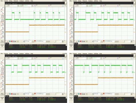
Figure 6 shows the waveform measurement results of VLC
lighting implemented using the proposed VPPM modulation to
support a 10% dimming step. The measurement environment (b)
is shown in Fig. 6(a). The computer in Fig. 6(a) is used for
Fig. 6. Waveform measurement results of VLC lighting
generating the transmitting and dimming data through a implemented using the proposed VPPM modulation:
graphic user interface. Waveforms at the output of the VPPM (a) waveform measurement environment and (b)
transmitter to LED luminaire have been measured using an waveform measurement results.
oscilloscope. From Fig. 6(b), a modulator based on the
proposed method can achieve pulse-width controllability for the value of commercial buildings by making them more
brightness control. comfortable and energy efficient [16]. The proposed method
VLC lighting including the VPPM modulator is able to can achieve more efficient complexity in comparison with a
change the illuminance by controlling the dimming level. In typical table-based method and is suitable to implement in
other words, the specific illuminance of the VLC lighting dimmable VPPM-VLC lighting systems. In particular, the
including the VPPM modulator can be obtained by controlling proposed method is more appropriate for applications such as
the dimming level of the VPPM modulator. Figure 7 shows the indoor audio-guiding and location-based services requiring fine
illuminance measurement environment and the measurement brightness control and a low data rate, whereas it is difficult to
results of 10 W VLC lighting implemented through the be applied to multimedia transmission based on a high data rate.
proposed VPPM modulation. In Fig. 7(a), the illuminance was This is because the dimming resolution of the VPPM
measured using the average value from nine illuminometers modulation is inversely proportional to the data rate when a
placed 3 × 3 vertically from a 10 W LED luminaire using the clock frequency that is typically dependent on the switching
proposed VPPM modulator. Figure 7(b) shows that the VLC speed of the LED module is specified. In terms of the evolution
luminaire with the proposed modulator can control the of VPPM-VLC lighting, VLC dimming control through
illuminance in a manner that is approximately proportional to cooperation with a backbone network to transfer scheduling-
the assigned dimming controlling level. data processed by an optimization algorithm can offer precise
The dimming controllability of LED lighting can increase location-based and enhanced context-aware services and
ETRI Journal, Volume 36, Number 6, December 2014 Jin-Doo Jeong et al. 909
http://dx.doi.org/10.4218/etrij.14.0114.0396References
In darkroom
VPPM-Tx platform [1] IEEE Std. 802.15.7, IEEE Standard for Local and Metropolitan
Area Networks — Part 15.7: Short-Range Wireless Optical
Communication Using Visible Light, New York, NY, USA, 2011.
10 W LED luminaire
[2] S. Rajagopal, R.D. Roberts, and S.-K. Lim, “IEEE 802.15.7
Visible Light Communication - Modulation Schemes and
1 m distance
Illuminometers Dimming Support,” IEEE Commun. Mag., vol. 50, no. 3, Mar.
2012, pp. 72–82.
[3] K. Lee and H. Park, “Modulations for Visible Light
Communications with Dimming Control,” IEEE Photon. Technol.
Lett., vol. 23, no. 16, Aug. 15, 2011, pp. 1136–1138.
[4] M. Rouissat, R.A. Borsali, and M.E. Chikh-Bled, “A New
(a)
Modified MPPM for High-Speed Wireless Optical
1,000
Communication Systems,” ETRI J., vol. 35, no. 2, Apr. 2013, pp.
980
188–192.
Measured illuminance (lx)
960
940 [5] I.E. Lee, M.L. Sim, and F.W.L. Kung, “Performance
920 Enhancement of Outdoor Visible-Light Communication System
900 Using Selective Combining Receiver,” IET Optoelectron., vol. 3,
880
no. 1, Feb. 2009, pp. 30–39.
860
840
[6] G. Ntogari et al., “Combining Illumination Dimming Based on
820 Pulse-Width Modulation with Visible-Light Communications
800 Based on Discrete Multitone,” J. Opt. Commun. Netw., vol. 3, no.
30 40 50 60 70 80
Dimming level assigned to VPPM modulator (%) 1, Jan. 2011, pp. 56–65.
(b) [7] K. Choi et al., “Visible Light Communications with Color and
Dimming Control by Employing VPPM Coding,” Int. Conf.
Fig. 7. Illuminance measurement results of 10 W VLC lighting
implemented using the proposed VPPM modulation: (a) Ubiquitous Future Netw., Phuket, Thailand, July 4–6, 2012, pp.
illuminance measurement environment and (b) 10–12.
illuminance measurement results. [8] K. Choi et al., “Visible Light Communication with Color and
Brightness Control of RGB LEDs,” ETRI J., vol. 35, no. 5, Oct.
energy savings in shopping malls or complex buildings [17]– 2013, pp. 927–930.
[18]; and it may contribute to an early adoption of VLC [9] K.L. Sterckx and P. Saengudomlert, “Visible Light
lighting. Communication via Dimmable LED Lamps Using Pulses of
Equal Shape,” European Conf. Netw. Opt. Commun., Newcastle
V. Conclusion upon Tyne, UK, July 20–22, 2011, pp. 48–51.
[10] M. Anand and P. Mishra, “A Novel Modulation Scheme for
This paper proposed a complexity-efficient architecture for Visible Light Communication,” IEEE India Conf., Kolkata, India,
a VPPM design supporting simultaneous wireless data Dec. 17–19, 2010, pp. 1–3.
transmission and dimming control. The proposed architecture [11] P.-Y. Chen and Y.-M. Lin, “A Low-Cost VLC Implementation
is based on sample counting, transition-point control, and two for MPEG-4,” IEEE Trans. Circuits Syst.—II: Exp. Briefs, vol.
2 × 1 muxes, which are composed of relatively simple logic, 54, no. 6, June 2007, pp. 507–511.
and its complexity is slightly sensitive to changes in the [12] S.-C. Hsia, “Prototyping Implementation for Low-Complexity
dimming resolution. The implementation efficiency can then Real-Time MPEG-2 Variable Length Encoder,” IEEE Int.
be achieved using the proposed method, as compared with Workshop System-on-Chip Real-Time Appl., Calgary, Canada,
a conventional codeword-table method, particularly in June 30–July 2, 2003, pp. 386–389.
applications requiring a high dimming-resolution controlled [13] V. Pedroni, Circuit Design with VHDL, Cambridge, MA, USA:
VLC. Finally, the additional researches on the communication MIT Press, 2004, pp. 515–535.
performance analysis with respect to dimming level and the [14] Mentor Graphics, ModelSim – Leading Simulation and
impact of interference in VPPM-VLC system for further Debugging, Mentor Graphics Corporation. Accessed Sept. 23,
studies will be continued. 2014. http://www.mentor.com/products/fpga/model
910 Jin-Doo Jeong et al. ETRI Journal, Volume 36, Number 6, December 2014
http://dx.doi.org/10.4218/etrij.14.0114.0396[15] Xilinx, FPGA Tutorials – ISE Design Suite Tutorials, Xilinx Inc. Il-Soon Jang is a principal member of the
Accessed Sept. 23, 2014. http://www.xilinx.com/training/fpga- engineering staff at the Electronics and
tutorials.htm Telecommunications Research Institute (ETRI),
[16] J. Gancarz, H. Elgala, and T.D.C. Little, “Impact of Lighting Daejeon, Rep. of Korea. He received his BS
Requirements on VLC Systems,” IEEE Commun. Mag., vol. 51, degree in information and communication
no. 12, Dec. 2013, pp. 34–41. engineering in 1997 and his MS and PhD
[17] H. Kim, S. Chang, and T.-G. Kang, “Enhancement of Particle degrees in communication circuit and system
Swarm Optimization by Stabilizing Particle Movement,” ETRI J., engineering in 1999 and 2005, respectively, from Chungbuk National
vol. 35, no. 6, Dec. 2013, pp. 1168–1171. University, Cheongju, Rep. of Korea. In 2000, he joined ETRI, where
[18] S.-K. Lim et al., “Entertainment Lighting Control Network he has worked on mobile communication systems. He is concentrating
Standardization to Support VLC Services,” IEEE Commun. Mag., on the area of visible light communication. He is one of the major
vol. 51, no. 12, Dec. 2013, pp. 42–48. contributors in developing the IEEE 802.15.7 standard on VLC.
Jin-Doo Jeong received his BS degree in Myung-Soon Kim is a senior member of the
electronic engineering in 1998 and his MS engineering staff at the Electronics and
degree in electronic and communication Telecommunications Research Institute (ETRI),
engineering in 2000 from Hanyang University, Daejeon, Rep. of Korea. She received her BS
Seoul, Rep. of Korea. In 2010, he joined the and MS degrees in information and
Electronics and Telecommunications Research communication engineering in 1999 and 2001,
Institute (ETRI), Daejeon, Rep. of Korea, where respectively, from Chonbuk National University,
he has worked on wireless personal area communication systems using Jeonju, Rep. of Korea. In 2001, she joined ETRI, where she has
UWB and chirp signals. He is a senior member of the engineering staff worked on mobile communication systems. She is concentrating on the
in ETRI, and he is concentrating on the area of visible light area of visible light communication
communications.
Tae-Gyu Kang received his BS and PhD
Sang-Kyu Lim received his BS degree in degrees in computer science in 1987 and
physics in 1995 and his MS and PhD degrees in 2002, respectively, from Kyonggi University,
electronics engineering in 1997 and 2001, Gyeonggi, Rep. of Korea. He received his MS
respectively, from Sogang University, Seoul, degree in computer science from Chung-Ang
Rep. of Korea. Since he joined the Electronics University, Gyeonggi, Rep. of Korea. He joined
and Telecommunications Research Institute the Electronics and Telecommunications
(ETRI), Daejeon, Rep. of Korea, in 2001, he Research Institute (ETRI), Daejeon, Rep. of Korea, in 2001 and as
has worked on high-speed optical transmission systems and worked on the CCS No.7 intelligent system and VoIP technologies. His
microwave/millimeter-wave circuit design. He is concentrating on the current research interests are system lighting and visible light
areas of visible light communication and lighting control networks. He communication. He is one of the major contributors in developing the
is one of the major contributors in developing the IEEE 802.15.7 and TTA standard and IEEE 802.15.7 standard on VLC. He is working as a
ANSI E1.45 standards on VLC. He is a principal member of the director at the LED Communication Research Section in ETRI.
engineering staff in ETRI and a senior member of the IEEE.
Jong-wha Chong received his BS and MS
degrees in electronics engineering from
Hanyang University, Seoul, Rep. of Korea, in
1975 and 1979, respectively and his PhD degree
in electronics and communication engineering
from Waseda University, Tokyo, Japan, in 1981.
Since 1981, he has been a professor of the
Department of Electronics Engineering at Hanyang University. From
1979 to 1980, he was a researcher at the C&C Research Center of
Nippon Electronic Company, Tokyo, Japan. From 1983 to 1984, he
was a visiting researcher at the Korean Institute of Electronics &
Technology, Seongnam, Rep. of Korea. He was a visiting professor at
ETRI Journal, Volume 36, Number 6, December 2014 Jin-Doo Jeong et al. 911
http://dx.doi.org/10.4218/etrij.14.0114.0396the University of California, Berkeley, USA, on two separate occasions
— the first being from 1986 to 1987 and the second from 2006 to 2007.
He was the chairman of the CAD & VLSI society of the Institute of
Electronics and Information Engineers (IEIE) in 1993, the president of
the IEIE in 2007, and the president of the KIEEE from 2009 to 2010.
He is currently the chairman of the Fusion SoC Forum. His current
research interests are SoC design methodology (including memory-
centric design, and the physical design and automation of 3D ICs);
indoor wireless communication SoC design for ranging and location;
video systems; and power IT systems.
912 Jin-Doo Jeong et al. ETRI Journal, Volume 36, Number 6, December 2014
http://dx.doi.org/10.4218/etrij.14.0114.0396You can also read