2016-2017 Jaguar F-Pace - Road Service Quick Reference Guide - Quality and Education Services - Pedini.com
←
→
Page content transcription
If your browser does not render page correctly, please read the page content below
Road Service Quick Reference Guide
   2016-2017 Jaguar F-Pace

    Quality and Education Services
          AAA Automotive
           1000 AAA Drive
         Heathrow, FL 32746
              March 31, 2017
Index

       Quick Specifications and Information         2
       Start/Stop Switch Operation                  2
       Hood Release                                 2
       Rear Hatch Release                           3
       Electronic Parking Brake (EPB)               3
       Towing, Loading and Transporting             4
       Selecting Neutral                            6
       Neutral-Shift Interlock Override             6
       Jacking and Tire Service                     9
       Fuel Service                                 11
       Jump-Start Procedure                         12
       Electronic Key                               13
       Lockout Procedure                            14

Important Notice:

This publication should not be used while driving. The procedures in this publication
should only be used by qualified and trained personnel.

This Road Service Quick Reference Guide was developed to highlight some model-specific
information and common procedures for servicing or towing this vehicle. It is not all-
inclusive. For complete information: The applicable vehicles owner’s manual and the AAA
Towing and Service Manual should be used in conjunction with this guide.

The procedures recommended and described in this guide are effective methods of
performing light service and towing operations. Some of these procedures require the use
of auxiliary equipment specially designed for the purpose. The auxiliary equipment should
be used when and as recommended and whenever the trained operator deems it appropriate.
It is important to read the various WARNINGS, CAUTIONS and NOTES in this manual
in order to minimize the risk of personal injury to service personnel and or customers and
to avoid procedures which may damage the vehicle or render it unsafe. It is also important
to understand that these warnings, cautions and notes are not exhaustive. Neither AAA nor
the auto and towing equipment manufacturers could possibly know, evaluate and advise
the reader of all conceivable methods of towing or evaluate individual situations.
Accordingly, anyone who uses a towing procedure must be thoroughly convinced that
neither personal safety nor vehicle safety will be jeopardized by the selected procedure.

AAA is not responsible for changes made by the manufacturers to the vehicles or their
recommendations. Important changes in procedures and updates will be furnished to all
manual users at AAACampus.aaa.biz.

                                            1
QUICK SPECIFICATIONS AND INFORMATION:
Available Drivelines: AWD
F-Pace Base Curb Weight Front Axle Weight Rear Axle Weight
Diesel: 3,913 lbs. 2,348 lbs. 1,565 lbs.
Gasoline: 4,015 lbs. 2,409 lbs. 1,606 lbs.
Note: Weights represent the heaviest optioned models available.
Dimensions:
Length Width
All Models: 186.3 in. 81.5 in. (mirrors folded in)
Lug Nut Torque: 92 lb. ft. (125 Nm)
Inflate the temporary spare to 60 psi
Premium fuel is recommended
START/STOP (IGNITION) SWITCH OPERATION:
Note: The electronic key must be in the vehicle. When not detected, a message will display
on the driver’s display panel.
Ignition On-engine Off: Press the start/stop switch without depressing the brake
pedal.
To start the engine: Press the start/stop switch while depressing the brake pedal.
HOOD RELEASE:
Opening the Hood:
Pull the hood release handle located on the
driver’s side of the footwell.
The secondary hood release lever is located
underneath the center of the hood. Release by
pushing towards the passenger’s side of the
vehicle.
2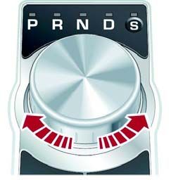
REAR HATCH RELEASE:
The Following Methods will Release the Rear Hatch:
Press the rear hatch release button on the
electronic key.
Press the rear hatch release button on the
dashboard.
Press the exterior rear hatch release button in
the center of the rear hatch.
ELECTRONIC PARKING BRAKE (EPB):
Operation:
Note: The EPB can be applied with the ignition On or Off. The ignition must be On to
release the EPB.
To apply the EPB: Lift the EPB switch briefly.
To release the EPB: Depress the brake pedal and
press down on the EPB switch briefly.
Note:
The EPB applies automatically when Park is
selected or when the ignition is switched Off.
To release the parking brake when the battery is
discharged, connect a booster pack to the jump-
start pins in the engine compartment and operate
the EPB switch normally.
WARNING: Do not connect the booster pack directly to the vehicle’s battery or damage
to the electrical system may occur.
3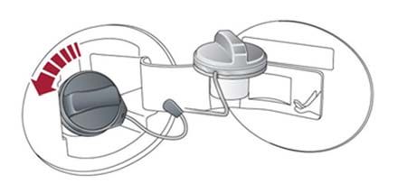
TOWING, LOADING AND TRANSPORTING:

The use of car carrier equipment is the preferred method of towing this vehicle. A
secondary, alternative wheel lift with dollies on the road wheels may be used when a car
carrier is not a practical solution. Additional ramping may be required when loading the
car onto the car carrier.

                                               Car carrier is the recommended towing
                                               procedure.

                                               Secondary, Alternative Procedure: Wheel
                                               lift with dollies. This method should be used
                                               when a car carrier is not a practical
                                               solution.

                                               Slingbelt towing is not an approved
                                               procedure. Vehicle damage may occur by
                                               this means.

CAR CARRIER LOADING:

The manufacturer provides an eyebolt for car carrier loading. It is located with vehicle’s
tool kit, in the rear cargo area. The eyebolt is installed in the front or rear eyebolt receiver.
Only use the eyebolt for vehicle loading. If used for any other purpose, vehicle damage,
serious injury or death may result. Do not use the eyebolt to secure the vehicle to the car
carrier, use wheel straps only. A secondary tether strap is recommended as a safety measure
for loading. See the Securing the Vehicle for Transport section for more details.

                                               4
Eyebolt Installation:
Front:
Carefully remove the cover on the
passenger’s side of the front bumper using a
non-marring or scratching flexible plastic
trim tool. Use caution not to scratch or
damage the cover or bumper cover.
Turn the eyebolt counter-clockwise into the
receiver until fully seated. Rusted threads
may require the use of a large screwdriver or
½ in. drive socket extension to assist in
threading the eyebolt into position.
Caution: Do not apply excessive force or
over-tighten. Thread damage may occur.
Rear:
Carefully remove the cover on the driver’s
side of the rear bumper using a non-marring
or scratching flexible plastic trim tool. Use
caution not to scratch or damage the cover or
bumper cover.
Turn the eyebolt counter-clockwise into the
receiver until fully seated. Rusted threads
may require the use of a large screwdriver or
½ in. drive socket extension to assist in
threading the eyebolt into position.
Caution: Do not apply excessive force or
over-tighten. Thread damage may occur.
5SELECTING NEUTRAL:
The transmission uses an electronic gear selector that prevents the transmission from being
placed in Neutral unless the engine is running. A shift interlock override is used to
mechanically place the transmission in Neutral for flatbed loading and unloading.
Choose the correct method based on the condition of the vehicle:
Placing the Vehicle in Neutral -- Minor Mechanical, Engine Starts:
This procedure for selecting Neutral should only be used if the vehicle’s engine can be
safely started without causing further mechanical damage. An example would be a
vehicle being towed for multiple flats or a non-engine related minor mechanical
condition.
Caution: You must use wheel chocks to secure the vehicle until you are ready to load.
Step 1 Selecting Neutral:
Deploy wheel chocks to secure the vehicle.
With the electronic key inside the vehicle, press the
Start/Stop switch once while depressing the brake pedal to
start the vehicle. Continue to press on the brake pedal.
The gear selector knob will rise from its retracted position
in the console.
The transmission will initially be in Park. Rotate the gear
selector knob to Neutral.
Press the Start/Stop switch once to turn the vehicle off.
The vehicle will remain in Neutral; however, the electric
parking brake is automatically applied.
Release the brake pedal.
Step 2 Disabling the Automatic Parking Brake
Feature:
Without pressing the brake pedal, press the Start/Stop
switch once to turn the ignition to On.
Press and hold the brake pedal.
Press down on the EPB switch to release the parking
brake.
Release the brake pedal.
Press and hold down the EPB switch.
Press the Start/Stop switch while continuing to hold
the EPB switch down. Continue to hold for 5
seconds.
Release the EPB switch.
At this point, the vehicle should be in Neutral with the parking brake released, and can be
loaded onto the car carrier.
6Placing the Vehicle in Neutral -- Without Starting the Engine
This method should be used when the engine cannot be started.
Caution: Prior to operating the shift interlock override, secure the vehicle to ensure it will
not roll. Deploy wheel chocks.
Operating the Shift Interlock Override:
The shift interlock override is located in the engine compartment on the driver’s side of the
intake manifold. To access, carefully remove the black plastic cover on the intake manifold
by lifting upward.
Lift the black lever on the shift
interlock override to the vertical
position (1).
Engage the securing latch to hold the
handle in position (2).
The transmission will remain in
Neutral until the shift interlock
override is released. Shift Interlock Override
Note: To return the transmission to Park,
release the securing latch (2) and move the
lever (1) back to the horizontal position.
Releasing the Parking Brake (EPB):
The EPB applies automatically when the ignition is turned Off. To temporarily disable the
parking brake:
With the ignition On-engine Off, depress the brake pedal and press down and hold
the EPB switch.
Within 5 seconds, turn the ignition Off.
Continue to hold down the EPB switch for 2 more seconds. The parking brake will
remain released until the next time the ignition is cycled On and Off.
Caution: If the ignition is cycled On and Off, this procedure must be repeated.
Releasing the Parking Brake when the Battery is Discharged:
Connect a booster pack to the jump-start pins in the engine compartment and operate the
EPB switch normally.
Note: If the electronic brake fails to release or you are unable to obtain Neutral, use wheel
skates or wheel dolly jacks on all non-rolling wheels.
WARNING: Do not connect the booster pack directly to the vehicle’s battery or damage
to the electrical system may occur.
7Securing the Vehicle for Transport:
Only wheel straps should be used to secure the vehicle for transport. Damage may occur if
wheel straps are not used.
When the vehicle is in its loaded position on the flatbed with the bed still in the deployed
position, secure the vehicle to prevent it from rolling by chocking the wheels and attaching
one wheel strap to the wheel closest to you. Follow all normal loading procedures to tie
down the rest of the vehicle and secure it for safe transport.
Caution: Do not over tighten the wheel straps or the vehicle may be damaged. Make sure
no metal portions of the strap contact the wheel. Avoid scratching any surfaces with the
wheel straps.
Placing into Park for Transport: Once the vehicle is secured to the carrier, reverse
whatever method was used to gain Neutral and restore the vehicle to the Park position to
assist in stabilizing the vehicle for transport.
Car Carrier Unloading:
When unloading, reverse the steps used to load the vehicle. Be sure to secure the vehicle
by returning it to Park and applying the parking brake or wheel chocks if the parking brake
will not apply.
8JACKING AND TIRE SERVICE:
Spare Tire Change Procedure:
Note:
Before jacking the vehicle, chock the tires and set the parking brake to ensure the
vehicle will not move.
Ensure the temporary spare tire is in serviceable condition and inflated to 60 psi.
Spare Tire Location:
The spare tire and the vehicle’s tool kit are
located under the removable floor panel in
the rear cargo area.
Caution: When removing the tire from the rear cargo area, prevent scratches or other
damage by protecting the bumper and other painted surfaces with a fender cover.
Note: Locking wheel nuts (if equipped) must be removed and reinstalled using a special
adaptor, which can be found in either the vehicle’s tool kit or the glovebox. Be sure to
return the adaptor to its original location and notify the member where you stowed it.
Jacking Points
Use the jacking points shown above. Place the jack in its proper location. Observe all
standard jacking precautions and ensure that the vehicle is on firm, level ground and that
the wheels are chocked. As the jack comes in contact with the vehicle body, ensure that it
is contacting the correct and solid location on the vehicle.
Wheel Installation:
When a wheel is installed, always remove any corrosion, dirt or foreign materials present
on the mounting surfaces of the wheel or the surface of the wheel hub, brake drum or brake
disc that contacts the wheel. Make sure that any fasteners that attach the rotor to the hub
are secured so they do not interfere with the mounting surfaces of the wheel. Installing
wheels without correct metal-to-metal contact at the wheel mounting surfaces can cause
the wheel nuts to loosen and the wheel to come off while the vehicle is in motion, resulting
in damage and loss of control.
9Wheel Lug Nut Torque Specifications:
Incrementally Torque Lug Nuts in the Pattern Shown Above to:
103 lb. ft. (140 Nm).*
*Torque specifications are for nut and stud threads free of dirt and rust.
WARNING: Failure to follow these precautions could cause the wheel nuts to loosen
and the tire to fall off, resulting in damage, serious injury or death.
Never use oil or grease on the wheel bolts or wheel nuts. Oil and grease may cause
the wheel nuts to be excessively tightened, leading to bolt or disc wheel damage.
In addition, the oil or grease can cause the wheel nuts to loosen and the wheel may
fall off, causing a serious accident. Remove any oil or grease from the wheel bolts
or wheel nuts.
When installing a tire, only use wheel nuts that have been specifically designed for
that wheel.
Check for any cracks or deformities in the bolt screws, nut threads or bolt holes of
the wheel.
Never install a wheel with excessive rust. Light surface rust should be cleaned off
the wheel and mounting surface.
Never install a tire with excessive tread wear or obvious defects.
Stowing the Flat Tire:
The flat tire should be properly stowed and secured in the spare tire well.
Note:
Inform the member/customer not to exceed 50 mph (80 km/h) while a temporary
spare tire is installed.
Have the lug nuts tightened to the specified torque as soon as possible and no more
than 100 miles (160 kilometers) after changing a flat tire.
Inform the member/customer that the Tire Pressure Monitoring System (TPMS)
warning light may flash or illuminate continuously until flat tire is repaired or
replaced and the system is reset. Other TPMS warning messages may be displayed
in the instrument cluster as well.
10FUEL SERVICE:
Caution: This vehicle may be equipped with a gasoline or diesel engine. Make certain to
add the correct fuel during fuel service. Adding the incorrect fuel may cause serious
damage to the engine and fuel system.
Use caution not to spill fuel on the painted surfaces of the vehicle during refueling. Use a
proper funnel that is free from dirt and debris.
The fuel filler door can be opened when the vehicle is unlocked by pushing it in slightly.
There is no emergency release for the filler door.
Gasoline Engine Fuel Octane Rating:
Premium unleaded gasoline with an Anti-Knock Index (AKI) octane rating of 91 or higher
should be used.
Diesel Engine Refueling:
A minimum of 1.1 US gallons (4 L) of diesel fuel is required to restart the vehicle.
After Refueling:
Depress and hold the brake pedal.
Press and hold the Start/Stop switch and crank the engine for 5 seconds.
Release the Start/Stop switch.
With the brake pedal still depressed, press and release the Start/Stop switch to crank
the engine. The engine should start within approximately 5 seconds.
Note: Diesel engine vehicles have a miss-fueling
flap in the fuel filler neck that requires the use of a
special fueling adaptor when adding fuel from a
diesel fuel can. A ordinary funnel cannot be
substituted. The adaptor is stowed in the cargo area
with the tire tools.
Caution: Failure to use the diesel fueling adaptor
when adding fuel from a diesel fuel can will cause Diesel Fueling Adaptor
damage to the fuel filler neck.
11JUMP-START PROCEDURE:
Note:
Follow all normal jump-starting precautions as outlined in other AAA/CAA
publications and those provided by the manufacturer.
Prior to connecting the boost source, ensure that all electrical accessories and the
ignition are turned Off, the transmission is in Park and the electronic key is removed
from the disabled vehicle.
Before attempting to start the vehicle, make sure the vehicle is in Park and that the
parking brake is applied and/or wheels chocked.
WARNING: The battery is located under the spare tire in the trunk. Do not jump-start the
vehicle at the battery or the electrical system may be damaged. Use the jump-start pins on
the passenger’s side of the engine compartment.
Caution: Use a fender cover to prevent scratches or other damage to the vehicle when
jump-starting.
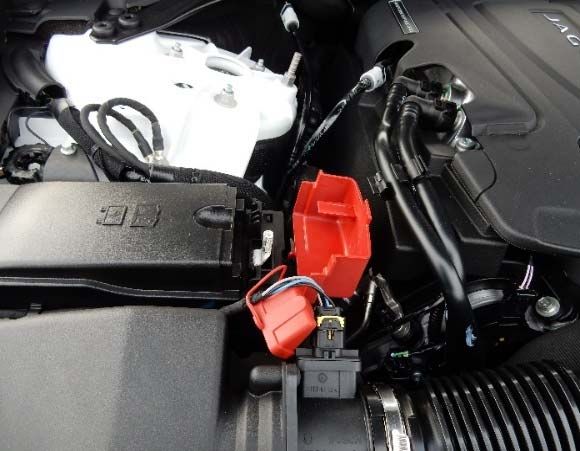
Jump-Starting:
Open the protective red cover on the
fuse box located on the passenger’s
side of the engine compartment.
Connect the positive (Red) cable to
the positive terminal jump pin.
Connect the negative (Black) cable
to the negative terminal jump pin.
Depress the brake pedal and start
the engine.
Disconnect in reverse order.
Close the protective red cover.
Secondary point to add power to the vehicle:
If power cannot be restored through the under hood jump
pins, the following procedure can performed directly at
the battery:
Follow all the previously listed Cautions and
Warnings.
Connect the positive (Red) cable to the
positive terminal of the battery.
Connect the negative (Black) cable to the
battery hold down bolt.
12ELECTRONIC KEY:
The electronic key must be inside the vehicle and detected to activate the push-button,
Start/Stop system.
Removable Key Blade:
The electronic key also contains a removable
mechanical key blade that is used to mechanically
lock or unlock the driver’s door.
To access the key blade, slide the cover on
the side of the key toward the top. The key
blade can then be removed and unfolded.
Unlocking the Driver’s Door using the Key Blade:
The driver’s door lock cover has a key
symbol embossed on it and a slot for the key
blade at the bottom. Use the key blade to
gently pry the driver’s door lock cover off.
There is a mechanical key cylinder under the
lock cover, which can be unlocked with the
key blade. Use caution not to damage the
paint or lock cover during removal.
To reinstall the door lock cover, locate the top
retaining lugs first. Press down and latch
inward to the single bottom lug. The lug
clicks into the locked position. Check the
security of the cover to make sure it is
properly attached and does not fall off after
the vehicle is moving.
If the Electronic Key is not Detected, try the Following:
Hold the electronic key against the left side
of the steering column with the buttons facing
out. Depress the brake pedal and start the
engine using the start/stop switch.
Activity Key:
This vehicle is available with an optional wristband
called the activity key. The activity key locks and
unlocks the vehicle when it is placed against the J on the
rear hatch. When used, it disables any electronic key left
inside the vehicle. Additional information is available in
the owner’s manual.
13LOCKOUT PROCEDURE:
WARNING: JAGUAR MODELS ARE LOCKSMITH OR TOW ONLY: It is not
recommended to attempt conventional entry on these vehicles, except in the case of an
extreme emergency. Door placement on these vehicles is quite tight and the high potential
for costly damage to the vehicle may occur. If entry must be attempted, exercise extreme
caution.
Note: These vehicles may be equipped with the immobilizer anti-theft system that may
disable the vehicle even after the electronic key is retrieved. The use of an airbag-style
wedge can be beneficial.
OPENING INSTRUCTIONS:
1. Using one or two wedges, carefully open a
small gap at the upper rear corner of the right
front door. Use a plastic strip or sheet to
protect surfaces from scratching.
2. Use a long reaching tool with an ″L″ tip on
the end. Apply tape to the tool tip to help
improve its ability to grip and protect interior
trim from scratching.
3. Insert the tool through the gap created by
wedging and maneuver the tip to contact the
interior door release handle.
4. Catch the handle from above and pull to
unlock the door. A double pull on the door
handle may be needed to unlock the vehicle.
5. Remove the wedges before attempting to
open the door.
ALTERNATE METHOD: Use the method listed
above, but depress the electric unlock switch instead
of pulling on the inside door release handle.
Clean the glass and all surfaces in the entry area before leaving the vehicle.
CAUTION: Do not use excessive force. Wedge only as much opening as needed to enter
tool to avoid putting stress on the door glass.
187
14You can also read