A Capacitance Estimation of Film Capacitors in an LCL-Filter of Grid-Connected PWM Converters
←
→
Page content transcription
If your browser does not render page correctly, please read the page content below
94                                      Journal of Power Electronics, Vol. 13, No. 1, January 2013

                                                                                                 http://dx.doi.org/10.6113/JPE.2013.13.1.94
     JPE 13-1-11

     A Capacitance Estimation of Film Capacitors in an
      LCL-Filter of Grid-Connected PWM Converters
                          Hong-Jun Heo*, Won-Sang Im*, Jang-Sik Kim**, and Jang-Mok Kim†
                          †*
                           School of Electrical Engineering, Pusan National University, Busan, Korea
                           **
                             Control Team, Motor BU Division, LG Electronics, Changwon, Korea

                                                                    Abstract

   A capacitor deterioration of LCL-filter grid-connected PWM converters is progressed by the self-healing mechanism. It leads to
the degradation of the filter performance and drop of power factor. Thus, it is required to diagnose fault-point of capacitors and
determine the replacement time. Typically, the fault of capacitors is determined when the capacitance is reduced up to 80% from
initial value. This paper proposes algorithm to the determine capacitor replacement time of an LCL filter. The algorithm takes the
advantage of change of the response on the injected resonant frequency corresponding to 80% value from the initial capacitance. The
results of the algorithm are demonstrated through simulations and experiments.

Key words: Deterioration of film capacitor, Grid connected PWM converter, Injection of resonant frequency, LCL filter

                                                                          system. In the case of L filters, a high input inductance should
                     I.   INTRODUCTION
                                                                          be used to reduce the current harmonics around the switching
                                                                          frequency. However, for applications above several kilowatts,
   In recent years, grid-connected ac/dc PWM converters have
                                                                          it becomes quite expensive to realize higher value filter
become the standard in industrial applications owing to their
                                                                          reactors. Moreover, the system dynamic response may become
advanced features including sinusoidal input currents with
                                                                          poor.
unity power factor and high-quality dc output voltages, and the
                                                                              An alternative and attractive solution to this problem is to
ability to work in rectifying and regenerating mode such as
                                                                          use an LCL filter as shown in Fig. 1. With this solution,
wind power and solar power [1], [2]. In the operation of
                                                                          optimum results can be obtained in the range of power levels
grid-connected PWM converters, fulfillment for current
                                                                          up to hundreds of kilovolt-amperes, still using quite small
harmonic restrictions is one of the critical issues. The use of
                                                                          values of inductors and capacitors [9]. From an economical
pulse width modulation (PWM) in conjunction with
                                                                          point of view, LCL filters are more attractive because stronger
closed-loop current control allows a sinusoidal input current to
                                                                          harmonics attenuation is relatively achievable compared to the
be achieved with a total harmonic distortion (THD) below 5%
                                                                          same size L filters and, consequently, lower switching
[3]-[7].
                                                                          frequency is allowable in the case of the same harmonic current
   Typical power device switching frequencies of between
                                                                          limitation. For this reason, LCL filters are more significant and
2~15 kHz can cause high-order harmonics that can disturb
                                                                          increasingly used [10]-[12].
other sensitive loads and equipments on the grid [8].
Accordingly, L filters or LCL filters are mainly inserted
between the grid and converter to reduce harmonic components
from PWM switching. Determination of the filter parameters is
a crucial design factor to enhance cost-effectiveness of the

    Manuscript received Oct. 7, 2011; revised Sep. 22, 2012
    Recommended for publication by Associate Editor Han-Ju Cha.
  †
    Corresponding Author : jmok@pusan.ac.kr
   Tel: +82-51-510-2366, Fax: +82-51-513-0212, Pusan Nat’l University
 *
   School of Electrical Eng., Pusan National University, Korea            Fig. 1. Grid-connected three-phase PWM converter.
**
  Control team, Motor BU Division, LG Electronics, Korea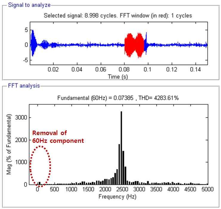
Journal of Power Electronics, Vol. 13, No. 1, January 2013                                 95

Fig. 2. FTA(Fault Tree Analysis) of MPPF Capacitor.
                                                                      Fig. 3. Mechanism of clearing in a MPPF capacitors: presence of
   As a third-order system, the LCL-filter tends to resonate at       a fault in the dielectric film.
the resonance frequency, which endangers system stability.
The resonance issue can be solved by active damping [13][14]
or passive damping [15].
   Another issue of LCL filters is deterioration of metalized
polypropylene film (MPPF) capacitors. The MPPF capacitors
are used in the LCL filter of the grid-connected PWM
converter due to their good reliability and good frequency
characteristics.
   The MPPF capacitors at max rated conditions typically have
service life ratings in the range from 60,000 hours to 150,000        Fig. 4. Evaporation of the metal with the only measurable damage
hours. It is not practical to do life testing on AC polymeric film    being a small loss of capacitance.
capacitors using max rated conditions since the test would last
                                                                      capacitor will continue to function with the only measurable
for many years [16].
                                                                      damage being a small loss of capacitance [18], [19].
   However, the MPPF capacitors lifetime can be significantly
                                                                         The capacitor deterioration from the self-healing mechanism
reduced by use for a long time with a large harmonic current,
                                                                      leads to degradation of a filter with increase in THD of the grid.
ripple voltage, hot spot temperature and harsh environments.
                                                                      In addition, it causes drop of power factor in grid-connected
Typically, the failure of a capacitor is determined when the
                                                                      PWM converter systems.
capacitance is reduced up to 80% from the initial value. The
                                                                         This paper proposes an algorithm in order to determine the
reasons of failures are the self-healing mechanism, corrosion of
                                                                      capacitor replacement time of the LCL filter when the
lead frame or burn-out as shown in Fig. 2 [17].
                                                                      capacitance is reduced up to 80% from the initial value. The
   Especially, the self-healing mechanism of MPPF capacitors
                                                                      algorithm takes the advantage of change of the response on the
is the main cause of reduction in capacitance and increase in
                                                                      injected resonant frequency corresponding 80% from the initial
the equivalent series resistance (ESR) with aging as shown in
                                                                      capacitance.
Fig. 3. When a foil capacitor suffers dielectric breakdown, the
electrodes become connected through a low impedance
connection at the point where the fault occurred. At this point,
the part of the capacitor where the fault occurred is normally a      II.   EFFECTS ON GRID-CONNECTED CONVERTER BY
short circuit and unable to accept a charge. This problem does              CAPACITOR DETERIORATION OF LCL FILTER
not exist for the self-healing metalized electrode capacitors.           In grid-connected PWM converters, the capacitor
With a self-clearing electrode, the fault in the dielectric will      deterioration of the LCL filter causes the decrease of its
result in the thin metalized electrode in the immediate area of       capacitance. Then, the resonant frequency of the filter moves
the fault being vaporized or turned from a metal conductor into       toward switching frequency of the system as shown in Fig. 5.
a metal oxide insulator. If the fault should occur in the             As a result, it involves adverse effects on the system.
dielectric as shown in Fig. 3, the current will flow from one            First of all, one of adverse effects is performance
end sprayed connection, through one electrode, through the            degradation of the LCL filter. THD of grid-side increases
fault, to the opposite electrode and to the opposite end sprayed      depending on the decrease of capacitance. The resonant
termination. The current in the area of the fault will be trying to   frequency of initial capacitance is shown as in (1). When the
go through the metal conductor that is so thin that it is optically   capacitance is reached in diminished point up to 80% of initial
translucent. The amount of a current that can go through this         capacitance, the fault of capacitor is determined; the resonant
thin electrode is very limited. The electrode in the immediate        frequency of fault point can be gained as in (2). At a fault point
distance of the fault will be blown away; the current will be         of a capacitor, the resonant frequency increase 1.118 times
safely interrupted because this process and a fuse operation are      when compared to the initial value as in (3).
similar. Once the fault has been cleared, as shown in Fig.4, the
96                                              Journal of Power Electronics, Vol. 13, No. 1, January 2013

Fig. 5. Degradation of filter caused by capacitor deterioration.                Fig. 6. Drop of power factor caused by capacitor deterioration.

                                                                                   According to (4), (5) and (6), if initial capacitance decreases
                                                   Lcon + Lg                    up to 80%, the power factor correction (pfc) in a fault condition
                                         1
                    f res _ initial =                                  (1)      is to be 0.931 times as compared with the initially designed pfc
                                        2p     Lcon ´ Lg ´ Cintial
                                                                                as in (7).

                                    1             Lcon + Lg                                             Z g = R g + jX g         Z c = jX c
                 f res _ fault =                                      (2)
                                   2p        Lcon ´ Lg ´ 0.8Cintial                             Z g ×Zc
                                                                                        Zp =               = R P + jX P
                                                                                                Z g + Zc                                                   (4)
                        f res _ fault = 1.118 ´ f res _ initial       (3)                             Rg X   2
                                                                                                             c              R X c + (X c + X g )X g X c
                                                                                                                             2
                                                                                                                             g
                                                                                           =                           +j
                                                                                               R + (X g + X c )                  R 2 + (X g + X c )
                                                                                                 2                 2                                   2
                                                                                                 g
   Also, the capacitance reduction causes drop of power factor.                                                                    æ        Xp ö
In an LCL-filter based three-phase PWM converter, current                                       pfc initial = cos(q v - q p ) = cosç tan -1      ÷
                                                                                                                                   ç        R p ÷ø
                                                                                                                                   è                       (5)
sensors are located in a reactor of the converter-side as shown
in Fig. 6. Therefore, three-phase current of the converter-side                                                  æ        R 2 + (X c + X g )X g ö
                                                                                                            = cosç tan -1                          ÷
                                                                                                                 ç                 RX c            ÷
makes it possible to have a unity power factor control with                                                      è                                 ø
three-phase voltage of the grid. However, in the initial design                                                                 æ        Xp ö
                                                                                               pfc fault = cos(q v - q p ) = cosç tan -1      ÷
of the LCL filter, filter-side capacitors and grid-side reactors                                                                ç        R p ÷ø
                                                                                                                                è
have to be designed to be more than 95% of unity power factor                                                                                              (6)
                                                                                                             æ        R 2 + (0.8 X c + X g )X g        ö
because the phase current of the grid-side are outside the                                              = cosç tan -1                                  ÷
                                                                                                             ç                 0.8 X c R               ÷
control domain of the converter system.                                                                      è                                         ø

Fig. 7. The control block of grid-connected PWM converter for proposed diagnosis.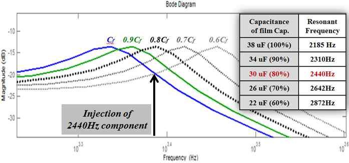
Journal of Power Electronics, Vol. 13, No. 1, January 2013 97
magnitude A: The gain in case of initial capacitance
B: The gain in case of fault capacitance
B
A
Initial 80% of
Injected capacitace initail capacitace
component
ωcc ωres_intial ωres_fault fsw /2
Fig. 9. Change of Bode-plot by capacitor deterioration of LCL
The injection of the resonant frequency component is
performed in the d-axis reference voltage during one period of
the grid fundamental frequency as shown in Fig.7. It is because
the active power (q-axis component) is almost unaffected and
the diagnosis of capacitor deterioration is possible to be
independent of the load.
As shown in (8), the component that adds the resonant
frequency of the capacitor fault-point and the fundamental
frequency of the grid is injected into the d-axis reference
voltage. Next, using the dq inverse transform, the injected
component in d-axis voltage reference is transformed into the
reference phase voltage (10) through (9). The injected resonant
component of the reference phase voltage affects the capacitor
voltage of the LCL-filter according to the gain of the LCL
transfer function.
Vde* _ inj = M inj sin[(w res _ fault + w grid )t ]
(8)
M inj M inj
Vds* _ inj = sin(w res _ fault t ) - sin[(w res _ fault + 2w grid )t ]
Fig. 8. The flowchart for proposed diagnosis. 2 2
(9)
M inj M inj
(7) Vqs* _ inj = cos(w res _ fault t ) - cos[(w res _ fault + 2w grid )t ]
pfc fault = 0.931´ pfcinitial 2 2
M inj M inj
V a*_ inj = sin(w res _ fault t ) - sin[(w res _ fault + 2w grid ) t ]
2 2
III. ALGORITHMS FOR REPLACEMENT TIME AND M inj 2 M inj 2
DETERIORATION DIAGNOSIS OF CAPACITOR Vb*_ inj = sin(w res _ fault t - p ) - sin[(w res _ fault + 2w grid - p ) t ](10)
2 3 2 3
IN LCL FILTER M inj 2 M inj 2
V c*_ inj = sin(w res _ fault t + p ) - sin[(w res _ fault + 2w grid + p ) t ]
2 3 2 3
The block diagram of a three-phase grid-connected PWM B. Voltage estimation of capacitor in LCL filter
converter system for the diagnosis is shown in Fig.7; Fig.8
shows the flowchart for the proposed diagnosis and The capacitor-side voltages of Fig. 10 can be estimated by
replacement time of the filter-side capacitor. (11) due to sensing of the converter-side current and
parameters of the LCL-filter.
A. Injection of resonant frequency component
*
d icon _ abc
corresponding to fault capacitance value vˆcf _ abc = vabc - Lcon - Rcon icon _ abc (11)
dt
In the proposed algorithms, the resonant frequency of the
capacitor fault point is used to detect the capacitor replacement
time as shown in Fig.9. When the resonant frequency is moved
by the decrease in capacitance, the response gain to the
injection component is increased from A-point to B-point due
to the changed transfer function of the LCL filter.
Fig. 10. Single-phase equivalent circuit for voltage estimation of
film capacitor side.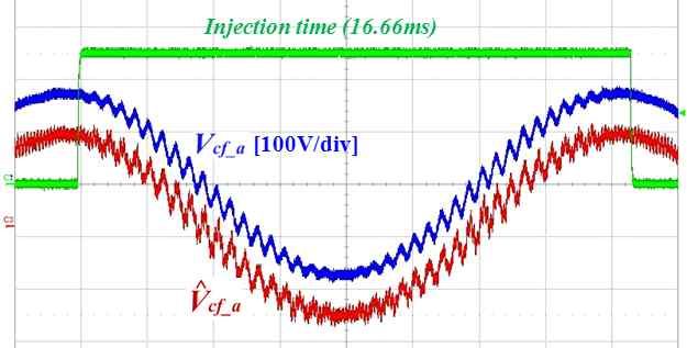
98 Journal of Power Electronics, Vol. 13, No. 1, January 2013
capacitor deterioration, the proportion value gabc by experiment
continues to increase until the capacitance-decrease reaches
80% point of the initial capacitance.
1 n (14)
V̂cf _ ave _ abc = å V̂cf _ BPF _ abc (kt )
T k =1
V̂cf _ ave _ abc _ measured
g abc = (15)
V̂cf _ ave _ abc _ initial
In addition, through the transfer function (16) of the
LCL-filter, the magnitude gain according to each frequency
can be calculated exactly. Consequently, the magnitude gain of
response on the injected frequency component winj can be
Fig. 11. Quality factor and Gain curve of Band Pass Filter. obtained by using (16) and (17).
Rd 1
s+
Lcon Lg CLcon Lg
sM (s ) = (16)
æ R R ö æ Lcon + Lg ö
s 2 + ç d + d ÷s + ç ÷
ç Lcon Lg ÷ ç CLcon Lg ÷
è ø è ø
Rd 1 Lcon + Lg æ Rd R ö
k1 = k2 = wres = z=
1 ç + d÷ (17)
Lcon Lg Lcon Lg CLcon Lg 2wres ç Lcon Lg ÷
, , , è ø
Before the deterioration of a capacitor, when the capacitance
of the filter-side capacitor keeps the initial value, the magnitude
Fig. 12. Gain curve of High Pass Filter. gain is expressed as in (18). However, if the capacitance
decreases up to the fault-point, the magnitude gain is calculated
C. Detection of Only Response on the Injection as in (19) because the injected frequency is equal to the
Component in Estimated Capacitor Voltage resonant frequency of the LCL-filter. The proportion value r of
The second-order band pass filter (BPF) is used to detect of (20) and (21) by calculation of the transfer function is shown in
response on the injected resonant frequency component in the (20).
estimated capacitor-side voltage. The transfer function of the k1winj + k 2 / C f _ initial
winj M intial = (18)
BPF is shown in (12). Quality factor, band-width and gain
curve of BPF can be confirmed in Fig.11. Also, high pass filter
2
w res (
_ initial - w 2 2
inj + (2zw ) w
res _ initial inj ) 2
(HPF) needs to remove the unnecessary low-order harmonic
components as in (13) and Fig. 12. Also, with regard to grid k1winj + k 2 / C f _ fault
winj M fault = (19)
frequency harmonics, the cut-off frequency of the HPF has to 2zw inj
wres =winj
be selected [20].
winj M fault
r= (20)
K BPF (w res _ 0.8Cf / Q BPF ) s winj M initial
Vˆcf _ BPF _ abc ( s ) = Vˆcf _ abc ( s ) (12)
s 2 + (w res _ 0.8Cf / Q BPF ) s + w res
2
_ 0.8Cf
s
Vˆcf _ HPF _ abc ( s ) = Vˆcf _ BPF _ abc ( s )
s + w cut _ off (13)
C. Detection for Replacement Time of Capacitor @ @
The estimated capacitor voltage through the BPF and HPF is
^
averaged by (14). Average capacitor voltage (Vcf_ave_abc_initial) in
initial capacitance must remember because it is used as
standard value for diagnosis. Since then, periodically measured
^
average capacitor voltage (Vcf_ave_abc_measured) is compared with Fig. 13. Difference of dB gain between initial capacitance and
^
Vcf_ave_abc_initial as in (15). According to the progress of the faulty capacitance.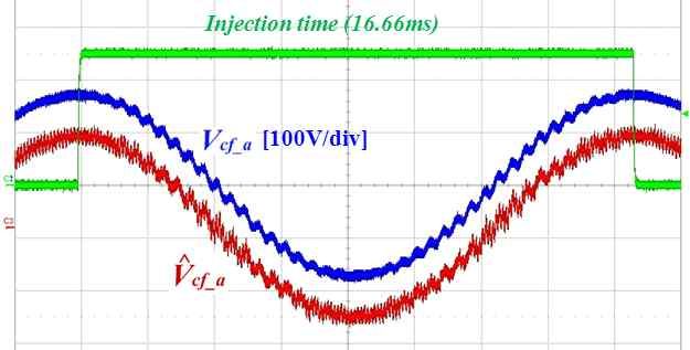
Journal of Power Electronics, Vol. 13, No. 1, January 2013                               99

Fig. 14. Configuration of experimental system.                                                  Fig. 15. Experimental setup.

                                                                 TABLE I
                                                  SIMULATION AND EXPERIMENT CONDITIONS

   As a result, the deterioration fault of the filter-side capacitor     to prove the algorithm, the capacitor of LCL-filter is designed
is determined through comparison between experimental gabc               to be able to select between the initial value 38uF and the fault
and calculated r as shown in (21). By multiplying the gain of            value 30uF.
0.9, the fault flag of the capacitor occurs when the capacitance            Fig. 16 shows the movement of the bode plot according to
decreases up to 82%. The difference in dB is almost equal to             the increase of the resonant frequency caused by the capacitor
the experimental value and calculated value as shown in Fig.             deterioration. Because the fault of the capacitor is determined
13. However, the value 0.9 needs to be multiplied in order to            when the capacitance is reduced up to 80% from the initial
improve the reliability of the diagnosis because there could be          value, the 2,440 Hz component is injected to determine the
a slight error.                                                          replacement time of filter-side capacitors.
                                                                            In this paper, only a-phase is used for the proof of the
                             g abc ³ 0.9 r                               algorithm in order to avoid redundancy.
                                                               (21)
                                                                           The component (22) that adds 2,440 Hz for the diagnosis and
                                                                         the fundamental frequency 60 Hz of the grid is injected into
   The configurations of the experimental system and                     d-axis voltage reference voltage during one period of the grid
experimental setup are shown in Fig. 14 and Fig. 15,                     frequency as shown in Fig. 17. It is possible to confirm that
respectively. A high-performance DSP chip (TMS 320VC33)                  q-axis reference voltage to active power component is almost
was used as a main controller, which operates at a 33.3-MHz              unaffected. Then, by using the dq inverse transform, (22) is
clock frequency and is capable of 32-bit floating-point                  transformed into a-phase reference voltage (23) as shown in
operation. The sampling period is 50us. The 22 kWatt                     Fig. 18.
three-phase back-to-back converter with the LCL-filter and the
3 kWatt load bank are used as shown in Fig. 14. The
                                                                                          Vde* _ inj = 20 sin[(2p × 2500)t ]          (22)
simulation and experimental conditions are listed in Table I.
The switching frequency is 10kHz, and the resonance of the
LCL-filter is designed as 2185Hz. As a matter of fact, in order                   Va* = 10 sin( 2p × 2440t ) - 10 sin( 2p × 2560t )   (23)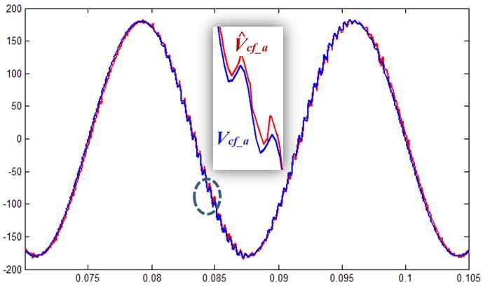
100                                   Journal of Power Electronics, Vol. 13, No. 1, January 2013

                                                                                             < In case of 38uF >

Fig. 16. Movement of resonant frequency caused by capacitor
deterioration.

                                                                                             < In case of 30uF >
                                                                                              (a) Simulation.

                            (a) Simulation.

                                                                                             < In case of 38uF >

                            (b) Experiment.

Fig.17. Injection of 2500Hz element to d-axis voltage reference.

                                                                                             < In case of 30uF >
                                                                                              (b) Experiment.
                                                                    Fig. 19. Voltage tracking of film capacitor side.

                                                                       The filter-side capacitor voltage can be estimated by (10)
                                                                    like results of Fig. 19. It can also find the estimated voltage.
                                                                    Allowing the deterioration of the capacitor from 38 uF to 30 uF,
                                                                    ripples of the capacitor-side voltage is increased by the injected
                            (a) Simulation.                         resonant frequency component. It is because the magnitude
                                                                    gain of the injected component has the largest gain at 30uF.
                                                                       The second-order BPF is used to detection of the ripple
                                                                    component (2,440 Hz) in the estimated voltage as shown in Fig.
                                                                    20. The digital filter of the second-order BPF is designed to
                                                                    have the 50 us sampling time, the bandwidth of 20 as in (24).
                                                                                ^
                                                                    Averaged Vcf_ave_a in the case of 38uF has to be set as the
                                                                    standard value for the diagnosis. When the capacitance of 38uF
                            (b) Experiment.                                                        ^
                                                                    is decreased down to 30uF, Vcf_ave_a represents the largest value
                                                                    because of the largest magnitude gain as shown in Fig.16.
Fig. 18. V*a by dq inverse transformation of V*de.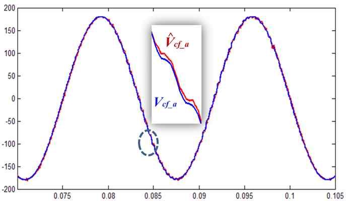
Journal of Power Electronics, Vol. 13, No. 1, January 2013 101
< In case of 38uF >
< Before HPF application >
< In case of 30uF >
(a) Simulation.
< In case of 38uF >
< After HPF application >
(a) Simulation.
< In case of 30uF >
(b) Experiment.
Fig. 20. Detection of 2440Hz component using BPF. < Before HPF application>
Vˆcf _ BPF _ a (n) =
(
20Tsamp Vˆcf _ HPF _ a (n) - Vˆcf _ HPF _ a (n - 1) )
2 2
1 + 20Tsamp w BPF Tsamp (24)
+
(
(2 + 20Tsamp ) Vˆcf _ BPF _ a (n - 1) - Vˆcf _ BPF _ a (n - 2) )
2 2
1 + 20Tsamp w BPF Tsamp
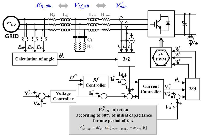
In Fig. 21, the HPF is used to remove unnecessary
component because the estimated capacitor voltage is
< After HPF application>
dominated by 60 Hz and low-order harmonic. If the HPF is not
(b) Experiment.
used to diagnosis, the error rate of the diagnosis can go up. The
digital HPF as shown in (25) is designed to remove up to 13th Fig. 21. Removal of low-order harmonic using HPF.
harmonic.
102                                                         Journal of Power Electronics, Vol. 13, No. 1, January 2013

                                                                                          the capacitor replacement time in the LCL-filter must be
                                                                                          carefully observed, since it has a negative effect on the
                                                                                          grid-connected PWM converter system; thus, the proposed
                                                                                          algorithm can be a good solution to increase the reliability and
                                                                                          safety of the whole system.

                                                                                                             ACKNOWLEDGMENT
                                                                                            This work has been supported by the Korea Institute of
                                                                                          Energy Technology Evaluation and Planning(KETEP) funded
                                                                                          by Ministry of Knowledge Economy in 2011(No.
   Fig. 22. Algorithm verification through comparison of results                          20112010100030-11-2-300).

                       2 - Tsampw HPF ˆ
  Vˆcf _ HPF _ a (n) =
                       2 + Tsampw HPF
                                        (
                                      Vcf _ HPF _ a (n - 1)       )               (25)                            REFERENCES
                        Tsampw HPF
                   +
                       2 + Tsampw HPF
                                        (Vˆ cf _ a   (n) + Vˆcf _ a (n - 1)   )           [1]  E. Twining and D. G. Holmes, “Grid current regulation of
                                                                                               a three-phase voltage source inverter with an LCL input
                                                                                               filter,” IEEE Trans. Power Electron., Vol. 18, No. 3, pp.
                                                                                               888-895, May 2003.
  When the capacitance is decreased up to 80% of the initial                              [2] R. Wu, S. B.Dewan, and G. R. Slemon, “Analysis of an
                                                                                               ac-to-dc voltage source converter using PWM with phase
value, the proportion value ga by an experiment is increased                                   and amplitude control,” IEEE Trans. Ind. Appl., Vol. 27,
up to 1.85 as expressed in (26) and the proportion value r from                                No. 3, pp. 355-364, Mar./Apr. 1991.
two calculated value of (27) is obtained as 1.83 by the transfer                          [3] M. Malinowksi, M. P. Kazmierkowski, S. Hansen, F.
                                                                                               Blaabjerg, and G. Marques, “Virtual flux based direct
function of the LCL-filter as shown in (28).
                                                                                               power control of three-phase PWM rectifiers,” IEEE Trans.
                                                                                               Ind. Appl., Vol. 37, No. 4, pp. 1019-1027, Jul./Aug. 2001.
                               V̂cf _ ave _ abc _ fault         3.62                      [4] M. Malinowksi, M. P. Kazmierkowski, S. Hansen, F.
                        ga =                                =        = 1.85        (26)        Blaabjerg, and G. Marques, “Virtual flux based direct
                               V̂cf _ ave _ abc _ initial       1.95
                                                                                               power control of three-phase PWM rectifiers,” IEEE Trans.
                       w inj M intial = 1335 w inj M fault = 2148                  (27)        Ind. Appl., Vol. 37, No. 4, pp. 1019-1027, Jul./Aug. 2001.
                                              ,                                           [5] C. Cecati, A. Dell’ Aquila, M. Liserre, and A. Ometto, “A
                                        winj M fault                                           fuzzy-logic based controller for active rectifier,” IEEE
                                   r=                  = 1.83                      (28)
                                        winj M initial                                         Trans. Ind. Appl., Vol. 39, No.1, pp. 105-112, Jan./Feb.
                                                                                               2003.
                                                                                          [6] C. Cecati, A. Dell’Aquila, A. Lecci, and M. Liserre,
   Fig. 22 shows that ga and r are equal to the difference (5.26                               “Implementation issues of a fuzzy-logic-based three-phase
dB) of the dB gain between the bode-plot of the initial                                        active rectifier employing only voltage sensors,” IEEE
                                                                                               Trans. Ind. Electron., Vol. 52, No. 2, pp. 378-385, Apr.
capacitance and the bode-plot of the faulty one at the finj.
                                                                                               2005.
                                                                                          [7] W. A. Hill and S. C. Kapoor, “Effect of two-level PWM
                                                                                               sources on plant power system harmonics,” in Conf. Rec.
                            IV. CONCLUSIONS                                                    IEEE-IAS Annu. Meeting, pp. 1300-1306, 1998.
   This paper has proposed a method for the replacement time                              [8] V. Blasko and V. Kaura, “A novel control to actively
                                                                                               damp resonance in input lc filter of a three-phase voltage
and the deterioration diagnosis of the film capacitor in the
                                                                                               source converter,” IEEE Trans. Ind. Appl., Vol. 33, No. 2,
LCL-filter. The resonant frequency component of 80% from                                       pp. 542-550, Mar./Apr. 1997.
the initial capacitance was injected into the reference voltage                           [9] H. R. Karshenas and H. Saghafi, “Basic criteria in
during one period of the grid frequency. The response of the                                   designing LCL filters for grid-connected converters,”
injection appears in the capacitor voltage according to the gain                               Industrial Electronics, 2006 IEEE International
                                                                                               Symposium, Vol. 3, pp. 1996-2000, 2006.
of the LCL filter. The BPF and the HPF are used to detect the
                                                                                          [10] Y. Lang, D. Xu, S. R. Hadianamrei, and H. Ma, “A Novel
only response from the injected component. The absolute value                                  design method of LCL type utility interface for
of the response through the BPF and HPF is averaged. Also,                                     three-phase voltage source rectifier,” in Proc. IEEE- PESC
through the transfer function of LCL filter, the magnitude gain                                '05 36th, pp. 313-317, Jun. 2005.
according to each frequency can be calculated exactly. As a                               [11] M. T. Bina and E. Pashajavid, “An efficient procedure to
                                                                                               design passive LCL-filters for active power filters,”
result, the deterioration fault of the filter-side capacitor is                                Electric Power Systems Research 79, pp. 606-614, 2009.
determined through the comparison between the experimental                                [12] M. Liserre, F. Blaabjerg and S. Hansen, “Design and
value and calculated value. The algorithm was verified through                                 control of an LCL-filter-based three-phase active
the simulations and experiments. Finally, the determination of                                 rectifier,” IEEE Trans. Ind. Appl., Vol. 41, pp. 1281-1291,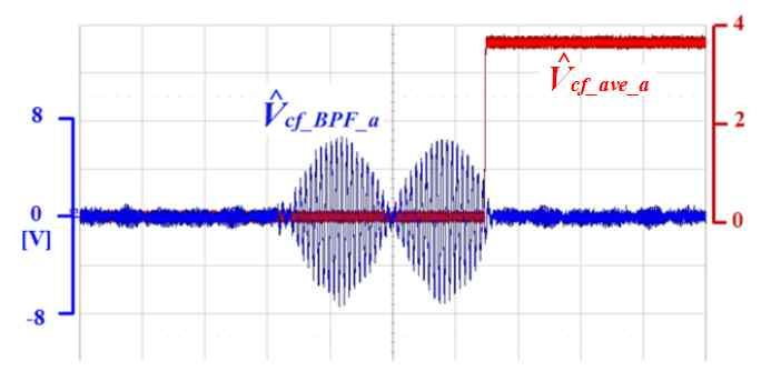
Journal of Power Electronics, Vol. 13, No. 1, January 2013                            103

     May 2005.                                                                            Jang-Mok Kim received the B.S. from
[13] S. Tang, L. Peng, and Y. Kang, “Active damping method                                Pusan National University, Korea, in 1988,
     using grid-side current feedback for active power filters                            and the M.S. and Ph.D. degrees from the
     with LCL filters,” Journal of Power Electronics, Vol. 11,                            Department of Electrical Engineering, Seoul
     No. 3, pp. 311~318, May 2011.                                                        National University, Seoul, Korea, in 1991
[14] F. Liu, Y. Zhou, S. Duan, J. Yin, B. Liu, and F. Liu,                                and 1996, respectively. From 1997 to 2000,
     “Parameter design of a two-current-loop controller used in                           he was a Senior Research Engineer with the
     a grid-connected inverter system with LCL filter,” IEEE                              Korea Electrical Power Research Institute
     Trans. Ind. Electron., Vol. 56, No. 11, pp. 4483~4491,            (KEPRI). Since 2001, he has been with the School of Electrical
     Nov. 2009.                                                        Engineering, PNU, where he is currently a Research Member
[15] M. Liserre, F. Blaabjerg, and S. Hansen, “Design and              with the Research Institute of Computer Information and
     control of an LCL-filter-based three-phase active                 Communication, a Faculty Member, and a head of LG
     rectifier,” IEEE Trans. Ind. Appl., Vol. 41, No. 5, pp.           Electronics Smart Control Center. As a Visiting Scholar, he
     1281~1291, Sep./Oct. 2005.                                        joined the Center for Advanced Power Systems (CAPS), Florida
[16] EMERSON Network Power company, Capacitor Age and                  State University, in 2007. His research interests include the
     Capacitors Have an End of Life.                                   control of electric machines, electric vehicle propulsion, and
[17] G. M. Buiatti, S. M. A. Cruz, and A. J. M. Cardoso,               power quality.
     “Lifetime of film capacitors in single-phase regenerative
     induction motor drives,” IEEE International Symposium
     SDEMPED 2007, pp. 356~362, Sep. 2007.
[18] M. H. El-Husseini, P. Venet, G. Rojat, and M. Fathallah,
     “Effect of the geometry on the aging of metalized
     polypropylene film capacitors,” IEEE 32nd Annual PESC.
     2001, Vol. 4, pp. 2061-2066, Jun. 2001.
[19] L. Hua, L. Fuchang, and Z. Heqing, “Study on metallized
     film capacitor and its voltage maintaining performance,”
     Vol. 45, No. 1, pp. 327~330, Jan. 2009.
[20] A. G. Abo-Khalil and Dong Choon Lee, “DC-link
     capacitance estimation in AC/DC/AC PWM converters
     using voltage injection,” IEEE Trans. Ind. Appl., Vol. 44,
     No. 5, pp. 1631-1637, Sep./Oct. 2008.

                 Hong-Jun Heo was born in Uiryeong, Korea,
                 in 1986. He received the B.S. in electrical
                 engineering from Pusan National University,
                 Busan, Korea, in 2011. He is currently
                 working toward the M.S. degree at Pusan
                 National University. His research interests
                 include   high    speed   generators   and
grid-connected DC-AC converters.

                       Won-Sang Im was born in Busan, Korea, in
                       1981. He received the B.S. and M.S. degrees
                       in Electrical Engineering from Pusan
                       National University, Busan, Korea, in 2007
                       and 2009, respectively, where he is currently
                       working toward the Ph.D. degree. His
                       research interests include power conversion,
                       electric machine drives, and their diagnosis
and fault-tolerance.

                    Jang-Sik Kim was born in Mokpo, Korea, in
                    1983. He received the B.S. degree in
                    electrical engineering from Korea Maritime
                    University, in 2010, and the M.S. degrees in
                    electrical engineering from Pusan National
                    University, Busan, Korea, in 2012. Since
                    2012, he has been with LG Electronics
                    Company Gyeongnam, Korea. His research
interests are control for home appliances, electric machines and
power converters.
You can also read