Modbus Communication for Circuit Breakers - Compact NSX, Compact NS and Masterpact NT/NW Circuit Breakers Quick Start Guide
←
→
Page content transcription
If your browser does not render page correctly, please read the page content below
COM-LVP38EN 07/2009

              Modbus Communication for
              Circuit Breakers
              Compact NSX, Compact NS and
              Masterpact NT/NW Circuit Breakers
              Quick Start Guide
              07/2009
COM-LVP38EN

              www.schneider-electric.com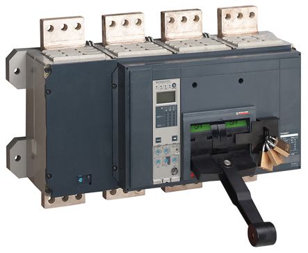
Schneider Electric assumes no responsibility for any errors that may appear in this document. If you have
    any suggestions for improvements or amendments or have found errors in this publication, please notify
    us.
    No part of this document may be reproduced in any form or by any means, electronic or mechanical,
    including photocopying, without express written permission of Schneider Electric.
    All pertinent state, regional, and local safety regulations must be observed when installing and using this
    product. For reasons of safety and to help ensure compliance with documented system data, only the
    manufacturer should perform repairs to components.
    When devices are used for applications with technical safety requirements, the relevant instructions must
    be followed.
    Failure to use Schneider Electric software or approved software with our hardware products may result
    in injury, harm, or improper operating results.
    Failure to observe this information can result in injury or equipment damage.
    © 2009 Schneider Electric. All rights reserved.

2                                                                                            COM-LVP38EN 07/2009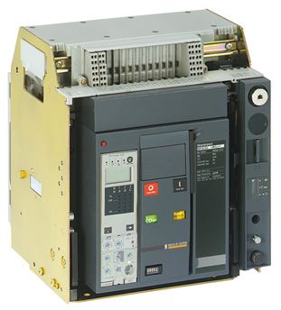
Table of Contents

                 Safety Information . . . . . . . . . . . . . . . . . . . . . . . . . . . . . . . . . . . . . . . . . . . .                                          5
                 About the Book . . . . . . . . . . . . . . . . . . . . . . . . . . . . . . . . . . . . . . . . . . . . . . .                                        7
       Chapter 1 Collecting Data About the Installation . . . . . . . . . . . . . . . . . . . . . . . . . . . .                                                      9
                       Presentation . . . . . . . . . . . . . . . . . . . . . . . . . . . . . . . . . . . . . . . . . . . . . . . . . . . . . . . . . . . . . . .   10
                       Advantage of Data Collection . . . . . . . . . . . . . . . . . . . . . . . . . . . . . . . . . . . . . . . . . . . . . . . . . .             11
                       Data Collection and Transmission Equipment . . . . . . . . . . . . . . . . . . . . . . . . . . . . . . . . . . . . .                         12
       Chapter 2 Installing the Communication Hardware . . . . . . . . . . . . . . . . . . . . . . . . . .                                                          15
                       Communication Connections . . . . . . . . . . . . . . . . . . . . . . . . . . . . . . . . . . . . . . . . . . . . . . . . . .                16
                       24 VDC Power Supplies . . . . . . . . . . . . . . . . . . . . . . . . . . . . . . . . . . . . . . . . . . . . . . . . . . . . . .            18
                       Sizing the 24 VDC Power Supplies . . . . . . . . . . . . . . . . . . . . . . . . . . . . . . . . . . . . . . . . . . . . . .                 19
       Chapter 3 Installing the Communication Software . . . . . . . . . . . . . . . . . . . . . . . . . . .                                                        21
                       Communication Parameters . . . . . . . . . . . . . . . . . . . . . . . . . . . . . . . . . . . . . . . . . . . . . . . . . . .               22
                       Modbus Registers . . . . . . . . . . . . . . . . . . . . . . . . . . . . . . . . . . . . . . . . . . . . . . . . . . . . . . . . . . .       24
                       List of Common Registers (Communication Profile) . . . . . . . . . . . . . . . . . . . . . . . . . . . . . . . . .                           26
                       Readout Examples . . . . . . . . . . . . . . . . . . . . . . . . . . . . . . . . . . . . . . . . . . . . . . . . . . . . . . . . . .         34
                       Communication Test . . . . . . . . . . . . . . . . . . . . . . . . . . . . . . . . . . . . . . . . . . . . . . . . . . . . . . . . .         35

COM-LVP38EN 07/2009                                                                                                                                                  3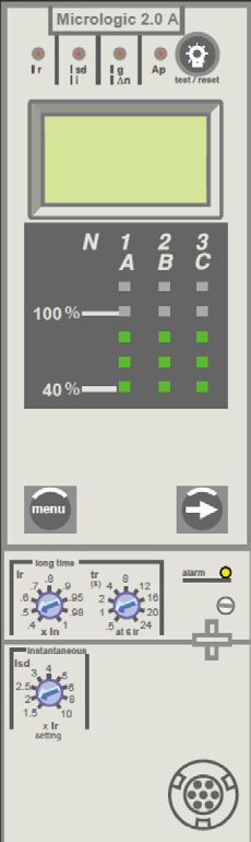
4 COM-LVP38EN 07/2009
Safety Information
                                                                                                                   §

Important Information

NOTICE
                      Read these instructions carefully, and look at the equipment to become familiar with the device before
                      trying to install, operate, or maintain it. The following special messages may appear throughout this
                      documentation or on the equipment to warn of potential hazards or to call attention to information that
                      clarifies or simplifies a procedure.

PLEASE NOTE
                      Electrical equipment should be installed, operated, serviced, and maintained only by qualified personnel.
                      No responsibility is assumed by Schneider Electric for any consequences arising out of the use of this
                      material.
                      A qualified person is one who has skills and knowledge related to the construction and operation of
                      electrical equipment and the installation, and has received safety training to recognize and avoid the
                      hazards involved.

COM-LVP38EN 07/2009                                                                                                             5
6 COM-LVP38EN 07/2009
About the Book

At a Glance

Document Scope
                      This quick start guide is designed to show users the advantages of implementing an information system
                      on their electrical installation using the data available in the circuit breakers. It explains broadly how to
                      implement this information system right from connecting the circuit breakers to the communication bus
                      through to selecting the data relevant to the user.

Validity Note
                      This document is valid for Compact NSX, Compact NS and Masterpact NT/NW circuit breakers
                      communicating using the Modbus protocol.

Related Documents

                      Title of Documentation                                                                  Reference Number
                      Modbus Compact NSX - User manual                                                        LV434106
                      Installation and setup manual for the Modbus Communication option for Masterpact        5100512864AA
                      Micrologic
                      Masterpact and Compact NS Modbus - User manual                                          COMBT32EN

                      You can download these technical publications and other technical information from our website at
                      www.schneider-electric.com.

User Comments
                      We welcome your comments about this document. You can reach us by e-mail at techcomm@schneider-
                      electric.com.

COM-LVP38EN 07/2009                                                                                                              7
8 COM-LVP38EN 07/2009
Collecting Data About the Installation
                      COM-LVP38EN 07/2009

                      Collecting Data About the Installation

                                                                              1

What's in this Chapter?
                      This chapter contains the following topics:
                                                                      Topic   Page
                         Presentation                                             10
                         Advantage of Data Collection                             11
                         Data Collection and Transmission Equipment               12

COM-LVP38EN 07/2009                                                                    9
Collecting Data About the Installation
Presentation
Introduction
The main function of a circuit breaker is to protect the installation. The circuit breaker is designed to trip
in the event of an electrical fault, thus isolating the faulty circuit. Nowadays it is also used as a metering
and communication tool to promote energy efficiency and:
Reduce energy costs
Optimize energy quality
Improve continuity of service
The circuit breaker concentrates all the measurements and states required to monitor the electrical
installation:
Circuit breaker status and control for managing the circuit breaker
Energy metering for optimizing and distributing the costs
Energy quality metering and maintenance data for reducing operating costs and improving continuity
of service
All this data is displayed locally on the circuit breaker and/or remotely on a remote screen. This data can
be made available and used via a communication network on a PC or PLC.
The Circuit Breaker Offer
Schneider Electric's low voltage circuit-breaker offer consists of the following circuit breakers:
NT NW
Masterpact
NSX NS
Compact
In (A)
100 250 630 800 1600 3200 6300
Available Data
The metering data required to monitor the electrical installation depends on the type of Micrologic trip unit
selected:
Circuit Breaker Compact NSX Compact NS/Masterpact
Type of Micrologic A E A P H
Current √ √ √ √ √
Energy, voltage, frequency, power, power √ √ √
factor
Energy quality: total harmonic distortion √ √
10 COM-LVP38EN 07/2009Collecting Data About the Installation
Advantage of Data Collection
Introduction
Keeping energy costs down and providing continuity of service for an installation are key factors in
ensuring a company remains competitive. To achieve these objectives, the user needs to know certain
information about the installation, such as consumption, energy quality, circuit breaker states, and
alarms. All this data is available in Compact and Masterpact circuit breakers equipped with Micrologic trip
units and is accessible remotely.
Managing the Electrical Installation
To manage the electrical installation efficiently, it is necessary to:
Collect data
Transmit this data to the supervision system
Make use of the data by means of supervisory software
The metering and communication functions in Compact and Masterpact circuit breakers enable data to
be collected and sent.
Making Use of Collected Data
Data can be used to:
Reduce energy costs due to improved awareness of consumption habits
Optimize energy quality in order to make the installation more reliable and optimize operating costs
Improve continuity of service to make maximum use of the installation's capacities
Reducing Energy Costs
The data can be used to save energy, thanks to the sub-metering function.
By measuring the circuit breakers' energy consumption, the user can:
Identify the heaviest consumers
Distribute the costs
Raise users' awareness of costs
Optimizing Energy Quality
Energy quality has a direct impact on operating costs:
Direct costs: Excessive energy consumption due to increased losses
Indirect costs:
Loss of production: Process malfunctions, nuisance tripping
Equipment costs: Reduction in the life of electrical equipment, reduced efficiency, oversizing
By using the data available in the circuit breakers, users can assess an installation's energy quality,
identify the causes of non-quality and check the effectiveness of any corrective solutions employed.
The following two measurements are key to monitoring energy quality:
The power factor, which reflects the reactive energy
The total harmonic distortion
Improving Continuity of Service
Electricity is vital for a site's activity. Analysis tools can be used on the data in order to increase familiarity
with the electrical installation and improve its reliability.
COM-LVP38EN 07/2009 11Collecting Data About the Installation
Data Collection and Transmission Equipment
Metering Data
The metering data available in the circuit breakers depends on the type of Micrologic trip unit selected
(see page 10).
Data on the Circuit Breaker Status (OF, SD and SDE Contacts) and Circuit Breaker Control
On Compact NSX circuit breakers, the BSCM module (Breaker Status & Control Module) is used to
determine the circuit breaker status remotely and to control it.
The illustration below shows a BSCM module.
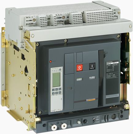
On Compact NS/Masterpact circuit breakers, the Modbus communication interface module (BCM) is
used to determine the circuit breaker status remotely and to control it.
The illustration below shows a BCM module.
The following circuit breaker status data is available when the BSCM module (Compact NSX) or the BCM
module (Compact NS/Masterpact) is present:
Open/closed position (OF contact)
Trip position (SD contact)
Fault trip position (SDE contact)
On Compact NSX circuit breakers, the communicating motor mechanism is used to control the circuit
breaker remotely. On Compact NS/Masterpact circuit breakers, the MX or XF communicating releases
are used to control the circuit breaker remotely.
The following circuit breaker controls are then available:
Open
Close
Reset
12 COM-LVP38EN 07/2009Collecting Data About the Installation
Status Data on the Withdrawable Circuit Breaker Positions (CE, CD, CT)
The Compact NS/Masterpact withdrawable circuit breakers communicate the circuit breaker position by
means of a chassis communication module (CCM) shown below:
++
bus
mod
CCM
CE
CE
+
CD
CD
CT
CT
The circuit breaker positions are:
Plugged in (CE contact)
Withdrawn (CD contact)
Test (CT contact)
The chassis communication module (CCM) is connected to the circuit breaker Modbus communication
interface module (BCM).
Circuit Breaker Communication
Compact NSX circuit breakers communicate by means of the Modbus communication interface module
external to the circuit breaker.
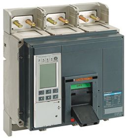
Masterpact circuit breakers communicate by means of the Modbus communication module (BCM) inside
the circuit breaker.
Compact NSX Circuit Breaker Compact NS/Masterpact Circuit Breaker
1
1
1 Modbus communication interface module 1 Modbus communication module (BCM)
COM-LVP38EN 07/2009 13Collecting Data About the Installation 14 COM-LVP38EN 07/2009
Installing the Communication Hardware
                      COM-LVP38EN 07/2009

                      Installing the Communication Hardware

                                                                            2

What's in this Chapter?
                      This chapter contains the following topics:
                                                                    Topic   Page
                         Communication Connections                              16
                         24 VDC Power Supplies                                  18
                         Sizing the 24 VDC Power Supplies                       19

COM-LVP38EN 07/2009                                                                  15
Installing the Communication Hardware
Communication Connections
Overview
Connection of circuit breakers to the Modbus communication network:
2 24 V
1
Modbus + 24 V
EGX / MPS100
blue
white
Modbus + 24 V
Rx- Rx+ Tx- Tx+
Modbus + 24 V
3
4 FDM121 FDM121
5 5
Compact NSX160 Compact NSX160
+ BSCM
Compact NSX400
+ BSCM
+ communicating motor mechanism
24 V
blue
white
+ +
A B A’ B’
F1- : 0 V
F2+ : 24 V
blue
white
0V
Network
24V
F1- : 0 V
Réseau
s
modbu
CCM
shield
A A
B B
Fault
A’ A’
B’ B’
Com.
Breaker
F2+ : 24 V
Disjoncteur
ss
Addre
sync.
+
CE
CD
CT
E6 E5 E4 E3 E2 E1
U
M
GERIN
MERLIN
Compact NS630b
6 Masterpact NT
1 Modbus communication interface module with stacking accessory (TRV00217)
2 24 VDC power supply for Micrologic trip units on Compact NSX and for communication modules
3 ULP cord
4 NSX Cord
5 Modbus cable + 24 VDC recommended: 50965 (Schneider Electric part number) or 7895A (Belden part number)
6 24 VDC power supply for Micrologic trip units on Compact NS/Masterpact
16 COM-LVP38EN 07/2009Installing the Communication Hardware
Detailed Diagram
Detailed connection of circuit breakers to the Modbus communication network:
G3 G4 EGX / MPS100
24 V Power Supply 24 V 0 V Rx- Rx+ Tx- Tx+
G1 G2
blue
white
blue Modbus line
white
termination
24 V
24 V
24 V
0V
D0
0V
D0
0V
D0
D1
D1
D1
Modbus Communication Interface Module (Compact NSX)
white
blue
CCM + -
Réseau
Network
A B A' B'
brown
yellow
white
Disjoncteur
blue
blue
white
Breaker
A B A' B'
CT CD CE + -
E6
E5
E4
E3
E2
E1
A'/Rx- white
B/Tx+ yellow
A/Tx- brown
0V
24 V red
B'/Rx+ blue
black
911 914 811 812 311 314
E6
E5
E4
E3
E2
E1
A'/Rx- white
B/Tx+ yellow
A/Tx- brown
0V
24 V red
B'/Rx+ blue
BCM
CT CD CE
(Compact NS630b)
Chassis
black
Masterpact NT
BCM
(Masterpact NT)
COM-LVP38EN 07/2009 17Installing the Communication Hardware
24 VDC Power Supplies
Introduction
Two 24 VDC power supplies are needed:
One 24 VDC power supply for the Compact NSX Micrologic trip units and all the communication
modules
One 24 VDC power supply for the Compact NS/Masterpact Micrologic trip units
Module Consumption
Compact NSX Micrologic and Communication Modules Consumption (mA)
Compact NSX Micrologic 30
BSCM module (circuit breaker status) 9
Front display module FDM121 21
Compact NSX Modbus communication interface module 21
Compact NS/Masterpact breaker Modbus communication module (BCM) 30
Compact NS/Masterpact chassis Modbus communication module (CCM) 30
Compact NS/Masterpact Micrologic Consumption (mA)
Compact NS/Masterpact Micrologic 100
M2C/M6C module 100
24 VDC Power Supply
Examples of power supplies available in the Schneider Electric catalog
Description Rating Part Number
24/30 VDC - 24 VDC - 1 A 1A 54440
Primary overvoltage category IV
Temperature: -25°C to +70°C
48/60 VDC - 24 VDC - 1 A 1A 54441
Primary overvoltage category IV
Temperature: -25°C to +70°C
100/125 VDC - 24 VDC - 1 A 1A 54442
Primary overvoltage category IV
Temperature: -25°C to +70°C
110/130 VDC - 24 VDC - 1 A 1A 54443
Primary overvoltage category IV
Temperature: -25°C to +70°C
200/240 VAC - 24 VDC - 1 A 1A 54444
Primary overvoltage category IV
Temperature: -25°C to +70°C
380/415 VAC - 24 VDC - 1 A 1A 54445
Primary overvoltage category IV
Temperature: -25°C to +70°C
100/500 VAC - 24 VDC - 3 A 3A ABL8RPS24030
Primary overvoltage category II
Temperature: 0°C to +60°C (derated to 80% of the current above 50°C)
18 COM-LVP38EN 07/2009Installing the Communication Hardware
Sizing the 24 VDC Power Supplies
Introduction
The calculated 24 VDC consumption required by circuit breakers for Modbus communication in the
previous architecture (see page 16) is given below.
Calculated Consumption of Compact NSX Micrologic Units and Communication Modules
Compact NSX Circuit Breaker Module Consumption (mA)
Compact NSX160 Compact NSX Micrologic 30
BSCM module (circuit breaker status) 9
Front display module FDM121 21
Modbus communication interface module 21
Compact NSX400 Compact NSX Micrologic 30
BSCM module (circuit breaker status) 9
Front display module FDM121 21
Modbus communication interface module 21
Compact NSX160 Compact NSX Micrologic 30
Modbus communication interface module 21
Total 213
Compact NS/Masterpact Circuit Breaker Module Consumption (mA)
Compact NS630b Breaker communication module (BCM) 30
Masterpact NT Breaker communication module (BCM) 30
Chassis communication module (CCM) 30
Total 90
The total consumption of the circuit breaker communication modules is therefore:
213 + 90 = 303 mA
Calculated Consumption of Compact NS/Masterpact Micrologic Units
Breaker Module Consumption (mA)
Compact NS630b Compact NS/Masterpact Micrologic 100
Masterpact NT Compact NS/Masterpact Micrologic 100
Total 200
Choice of Power Supplies
Since the power supply consumption for the Compact NSX Micrologic units and communication
modules (303 mA) is less than 1 A, any power supply rated 1 A is suitable.
Since the power supply consumption for the Compact NS/Masterpact (200 mA) Micrologic units is less
than 1 A, any power supply rated 1 A is suitable (see page 18).
COM-LVP38EN 07/2009 19Installing the Communication Hardware 20 COM-LVP38EN 07/2009
Installing the Communication Software
                      COM-LVP38EN 07/2009

                      Installing the Communication Software

                                                                             3
What's in this Chapter?
                      This chapter contains the following topics:
                                                                     Topic   Page
                         Communication Parameters                                22
                         Modbus Registers                                        24
                         List of Common Registers (Communication Profile)        26
                         Readout Examples                                        34
                         Communication Test                                      35

COM-LVP38EN 07/2009                                                                   21
Installing the Communication Software
Communication Parameters
Parameters
Parameters Compact NSX Compact NS/Masterpact
Permitted Values Default Value Permitted Values Default Value
Address 1...99 1 1...47 47
Baud rate 4800 Baud 19200 4800 Baud 19200
9600 Baud 9600 Baud
19200 Baud 19200 Baud
38400 Baud 38400 Baud
Parity None (2 stop bits) Even None (2 stop bits) Even
Even (1 stop bit) Even (1 stop bit)
Odd (1 stop bit) Odd (1 stop bit)
Configuring the Modbus Communication Interface Module with a Compact NSX
A Compact NSX circuit breaker's Modbus address is defined by means of 2 address switches located on
the front face of the Modbus communication interface module.
Example of configuring Modbus address 21:
By default, the Modbus communication interface module automatically detects the communication
parameters (baud rate and parity) when it is connected to the Modbus network (default configuration).
The communication parameters can also be defined manually using the RSU (Remote Setting Utility)
software.
Configuring the BCM with a Compact NS/Masterpact and Micrologic A
The Modbus address and communication parameters are defined using the keypad on the Micrologic A
trip unit.
Step Action Micrologic A
1
Press the and keys simultaneously to access the communication option
parameter settings.
ADXX is displayed on the screen, where XX is the currently defined Modbus
address.
2
Press briefly to set the Modbus address between 1 and 47.
3
Press for 3 s to confirm the Modbus address and then set the baud rate.
bXX.X is displayed on the screen, where XX.X is the currently defined baud rate.
4
Press briefly to set the communication speed to 19200 Baud (b19.2).
5
Press for 3 s to confirm the communication speed and then set the parity.
P.X is displayed on the screen, where X is the currently defined parity.
6
Press briefly to set the parity to Even (P.E).
7
Press for 3 s to confirm the parity and return to the metering menu.
22 COM-LVP38EN 07/2009Installing the Communication Software
Configuring the BCM with a Compact NS/Masterpact and Micrologic P or H
The Modbus address and communication parameters are defined using the keypad on the Micrologic P
or H trip unit.
Step Action Micrologic P or H
1
Press to access the configuration menu.
2 Select Configure com then Parameter com. to display the Modbus Com screen.
3
Press the and keys to select the address setting then the key to
confirm.
4
Press the and keys to define the address then the key to confirm.
5 Go back to step 3 to set the baud rate, then the parity.
Configuring the CCM with a Compact NS/Masterpact
Step Action CCM
1 Configure the BCM as described above.
2 Press the Address sync button.
3 The chassis communication module (CCM) is automatically configured with:
The same baud rate and parity as the breaker communication module (BCM)
The address assigned to the breaker communication module + 50
The breaker (BCM) and chassis (CCM) communication modules are automatically
connected to the rest of the network.
COM-LVP38EN 07/2009 23Installing the Communication Software
Modbus Registers
Table of Common Registers (Communication Profile)
The main information needed for remote supervision of a Compact NSX, Compact NS or Masterpact
NT/NW circuit breaker is contained in the table of common registers starting at register 12000.
This compact table of 113 registers can be read with a single Modbus request.
It contains the following information:
Circuit breaker status
Trip unit protection status
Real-time values of main measurements: current, voltage, power, energy, total harmonic distortion
The content of this table of registers is detailed in the List of Common Registers (Communication Profile)
section.
Use of these common registers is highly recommended to optimize response times and simplify use of
data.
NOTE: For Compact NS/Masterpact circuit breakers, the communication profile (table of common
registers) must be activated by writing 1 in register 800.
Maintenance Data Registers
Maintenance data for a Compact NSX, Compact NS or Masterpact NT/NW circuit breaker is not available
in the table of common registers.
This must be read by specific read requests according to the type of circuit breaker.
See registers 29851 onwards for Compact NSX.
See registers 9094 onwards for Compact NS/Masterpact.
Measurement Update Period
The update period for the common registers is:
1 second for the following measurements:
Voltage and voltage unbalance
Current and current unbalance
Active, reactive, apparent, and distortion power
Reactive power with harmonics
Power factor and fundamental power factor
Frequency
5 seconds for the following measurements:
Energy
Minimum and maximum real-time measurement values
Total harmonic distortion (THD)
24 COM-LVP38EN 07/2009Installing the Communication Software
Format des tableaux de registres
The register tables consist of the following columns:
Register Address R/W X Unit Type Range A/E A/P/H Description
Register: Number of the 16-bit register in decimal number format.
Address: Address of the 16-bit register (one less than the register number).
R/W: The register is either read-only (R), or read-write (R/W).
X: Scale factor. Scale 10 means that the register contains the value multiplied by 10. The actual value
is therefore the register value divided by 10.
Example
Register 12036 contains the network frequency. The unit is Hz and the scale factor is 10.
If the register contains the value 502, this means that the network frequency is
502/10 = 50.2 Hz.
Unit: Unit in which the information is expressed.
Type: Type of encoding data.
Range: Permitted values for this register, usually a subset of what the format allows.
A/E: Types of Micrologic Compact NSX trip unit for which the register is available.
Type A (ammeter): Current measurements
Type E (energy): Current, voltage, power and energy measurements
A/P/H: Types of Masterpact NT/NW and Compact NS Micrologic trip unit for which the register is
available.
Type A (ammeter): Current measurements
Type P (power): Current, voltage, power and energy measurements
Type H (harmonics): Current, voltage, power, energy and energy quality measurements
Description: Provides information about the register and the restrictions applying to it.
Data Types
The following data types appear in the Modbus register tables:
Label Description Range
UINT Unsigned 16-bit integer 0 to 65,535
INT Signed 16-bit integer -32,768 to +32,767
UDINT Unsigned 32-bit integer 0 to 4,294,967,295
DINT Signed 32-bit integer -2,147,483,648 to +2,147,483,647
STRING Text string 1 byte per character
Notes
The type column indicates the number of registers to be read in order to obtain the variable. For
example, UINT asks for one word to be read whereas DINT requires 2 words to be read.
Reading from an undocumented address results in a Modbus exception.
Variables stored in 2 words (energy, for example) are stored in big-endian, format, with the most
significant word transmitted first, and the least significant word transmitted second.
Digital values are given in decimal format. When there is an advantage in having the corresponding
value in hexadecimal format, this is given as a constant in C language: 0xdddd. For example, the
decimal value 123 is represented in hexadecimal format as 0x007B.
Non-functioning and non-applicable values are represented by 32,768 (0x8000 or 0x8000000 for 32-
bit values).
Out-of-limit values are represented by 32,767 (0x7FFF, for 16-bit values only).
For measurements which depend on presence of the neutral, value readout returns 32,768 (0x8000)
if not applicable. For each table where this appears, an explanation is given in a footnote.
COM-LVP38EN 07/2009 25Installing the Communication Software
List of Common Registers (Communication Profile)
Data Validity
Register Address R/W X Unit Type Range A/E A/P/H Description
12000 11999 R 1 - UINT - A/E A/P/H Indicates the validity of each bit in
the circuit breaker status register
(12001).
Circuit Breaker Status Register
Register Address R/W X Unit Type Range A/E A/P/H Bit Description
12001 12000 R — — UINT — A/E A/P/H — Circuit breaker status register
A/E A/P/H 0 OF status
0 = The circuit breaker is open
1 = The circuit breaker is closed
A/E A/P/H 1 SD trip indication
For Compact NS and NSX:
0 = No tripping
1 = The circuit breaker has tripped due to an
electrical fault or due to the release or
because the Push to trip button has been
pressed.
For Masterpact: Always 0
A/E A/P/H 2 SDE fault trip indication
0 = No tripping
1 = The circuit breaker has tripped due to an
electrical fault or during testing of the ground
fault protection or the Vigi protection.
— A/P/H 3 CH loaded (only with Masterpact motor
mechanism)
0 = Spring discharged
1 = Spring loaded
— — 4 Reserved
— A/P/H 5 PF ready to close
0 = Not ready to close
1 = Ready to close
— A/P/H 6 Distinction between Compact/Masterpact
0 = Compact
1 = Masterpact
— — 7...14 Reserved
A/E A/P/H 15 Data availability
If this bit is at 1, the circuit breaker status is not
available.
12002 12001 R — — UINT — — - - Reserved
12003 12002
Tripping Cause
The tripping cause register provides information about the cause of the trip for the basic protection
functions. When a bit is at 1 in the register, it indicates that a trip has occurred and has not been
acknowledged.
26 COM-LVP38EN 07/2009Installing the Communication Software
Register Address R/W X Unit Type Range A/E A/P/H Bit Description
12004 12003 R — — UINT — A/E A/P/H — Tripping cause for the basic protection functions
A/E A/P/H 0 Long time protection Ir
A/E A/P/H 1 Short time protection Isd
A/E A/P/H 2 Instantaneous protection Ii
A/E A/P/H 3 Ground fault protection Ig
A/E A/P/H 4 Earth leakage protection (Vigi module) IΔn
A/E A/P/H 5 Integrated instantaneous protection
A/E — 6 Internal failure (STOP)
— A 6 Other protections
— P/H 6 Internal failure (temperature)
— P/H 7 Internal failure (overvoltage)
— P/H 8 Other protection (see register 12005)
A/E — 9 Instantaneous with earth leakage protection (Vigi
module) on the trip unit
E — 10 Unbalance motor protection
E — 11 Jam motor protection
E — 12 Underload motor protection
E — 13 Long start motor protection
A/E — 14 Reflex tripping protection
A/E A/P/H 15 If this bit is at 1, bits 0 to 14 are not valid.
12005 12004 R — — UINT — — P/H — Tripping causes for the advanced protection
functions
12006 12005 R — — UINT — — — — Reserved
12007 12006
COM-LVP38EN 07/2009 27Installing the Communication Software
Overrun of the Protection Setpoints
The alarm setpoint registers provide information about overrun of the standard and advanced protection
setpoints. A bit is at 1 once a setpoint overrun has occurred, even if the time-out has not expired.
Register Address R/W X Unit Type Range A/E A/P/H Bit Description
12008 12007 R — — UINT — A/E P/H — Overrun of the standard protection setpoints
A/E P/H 0 Long time protection pick-up
— — 1...14 Reserved
A/E P/H 15 If this bit is at 1, bits 0 to 14 are not valid.
12009 12008 R — — UINT — — P/H — Overrun of the advanced protection setpoints
— P/H 0 Current unbalance
— P/H 1 Maximum current on phase 1
— P/H 2 Maximum current on phase 2
— P/H 3 Maximum current on phase 3
— P/H 4 Maximum current on the neutral
— P/H 5 Minimum voltage
— P/H 6 Maximum voltage
— P/H 7 Voltage unbalance
— P/H 8 Maximum power
— P/H 9 Reverse power
— P/H 10 Minimum frequency
— P/H 11 Maximum frequency
— P/H 12 Phase rotation
— P/H 13 Load shedding based on the current
— P/H 14 Load shedding based on the power
— P/H 15 If this bit is at 1, bits 0 to 14 are not valid.
12010 12009 R — — UINT — — P/H — Continuation of the previous register
— P/H 0 Ground fault alarm
— P/H 1 Earth leakage alarm (Vigi module)
— — 2...14 Reserved
— P/H 15 If this bit is at 1, bits 0 to 14 are not valid.
28 COM-LVP38EN 07/2009Installing the Communication Software
Alarms
The alarm register provides information about the pre-alarms and the user-defined alarms. A bit is set to
1 once an alarm is active.
Register Address R/W X Unit Type Range A/E A/P/H Bit Description
12011 12010 R — — UINT — A/E — — Pre-alarm register
A/E — 0 Long time protection time pre-alarm (PAL Ir)
A/E — 1 Earth leakage protection pre-alarm (Vigi
module) (PAL IΔn)
A/E — 2 Ground fault protection pre-alarm (PAL Ig)
— — 3...14 Reserved
A/E — 15 If this bit is at 1, bits 0 to 14 are not valid.
12012 12011 R — — UINT — A/E — — Register of user-defined alarms
A/E — 0 User-defined alarm 201
A/E — 1 User-defined alarm 202
A/E — 2 User-defined alarm 203
A/E — 3 User-defined alarm 204
A/E — 4 User-defined alarm 205
A/E — 5 User-defined alarm 206
A/E — 6 User-defined alarm 207
A/E — 7 User-defined alarm 208
A/E — 8 User-defined alarm 209
A/E — 9 User-defined alarm 210
— — 10...14 Reserved
A/E — 15 If this bit is at 1, bits 0 to 14 are not valid.
12013... 12012... R — — UINT — — — — Reserved
12015 12014
Currents
Register Address R/W X Unit Type Range A/E A/P/H Description
12016 12015 R 1 A UINT 0...20xIn A/E A/P/H Rms current on phase 1: I1
12017 12016 R 1 A UINT 0...20xIn A/E A/P/H Rms current on phase 2: I2
12018 12017 R 1 A UINT 0...20xIn A/E A/P/H Rms current on phase 3: I3
12019 12018 R 1 A UINT 0...20xIn A/E A/P/H Rms current on the neutral: IN (1)
12020 12019 R 1 A UINT 0...20xIn A/E A/P/H Maximum of I1, I2, I3, and IN
12021 12020 R 1 (2) UINT — A/E A/P/H Ground fault current Ig. The range depends on
the nominal current In.
12022 12021 R 1 (3) UINT — A/E A/P/H Ground leakage current IΔn. The range
depends on the nominal current In.
(1) Value cannot be accessed for motor applications and in cases of 3-pole circuit breakers without external neutral current transformer
(ENCT).
(2) This value is only available:
For Masterpact NT/NW and Compact NS Micrologic 6.0 trip units, expressed in amps
For Compact NSX Micrologic 6.2 and 6.3 trip units, expressed as %Ig
(3) This value is only available:
For Masterpact NT/NW and Compact NS Micrologic 7.0 trip units, expressed in milliamps
For Compact NSX Micrologic 7.2 and 7.3 trip units, expressed as %lΔn
COM-LVP38EN 07/2009 29Installing the Communication Software
Maximum Current Values
Register Address R/W X Unit Type Range A/E A/P/H Description
12023 12022 R 1 A UINT 0...20xIn A/E A/P/H Maximum rms current on phase 1: I1
12024 12023 R 1 A UINT 0...20xIn A/E A/P/H Maximum rms current on phase 2: I2
12025 12024 R 1 A UINT 0...20xIn A/E A/P/H Maximum rms current on phase 3: I3
12026 12025 R 1 A UINT 0...20xIn A/E A/P/H Maximum rms current on the neutral: IN (1)
12027 12026 R 1 A UINT 0...20xIn A/E A/P/H Maximum rms current out of the 4 previous
registers
12028 12027 R 1 (2) UINT — A/E A/P/H Maximum ground fault current Ig. The range
depends on the current In.
12029 12028 R 1 (3) UINT — A/E A/P/H Maximum ground leakage current IΔn. The range
depends on the nominal current In.
(1) Value cannot be accessed for motor applications and in cases of 3-pole circuit breakers without external neutral current transformer
(ENCT).
(2) This value is only available:
For Masterpact NT/NW and Compact NS Micrologic 6.0 trip units, expressed in amps
For Compact NSX Micrologic 6.2 and 6.3 trip units, expressed as %Ig
(3) This value is only available:
For Masterpact NT/NW and Compact NS Micrologic 7.0 trip units, expressed in milliamps
For Compact NSX Micrologic 7.2 and 7.3 trip units, expressed as %lΔn
Voltages
Register = 0 if the voltage < 25 V.
Register Address R/W X Unit Type Range A/E A/P/H Description
12030 12029 R 1 V UINT 0...850 E P/H Rms phase-to-phase voltage V12
12031 12030 R 1 V UINT 0...850 E P/H Rms phase-to-phase voltage V23
12032 12031 R 1 V UINT 0...850 E P/H Rms phase-to-phase voltage V31
12033 12032 R 1 V UINT 0...850 E P/H Rms phase-to-neutral voltage V1N (1)
12034 12033 R 1 V UINT 0...850 E P/H Rms phase-to-neutral voltage V2N (1)
12035 12034 R 1 V UINT 0...850 E P/H Rms phase-to-neutral voltage V3N (1)
(1) Value cannot be accessed for motor applications and in cases of 3-pole circuit breakers without external neutral voltage transformer
(ENVT).
Frequency
When the software cannot calculate the frequency, it returns Not available = 32,768 (0x8000).
Register Address R/W X Unit Type Range A/E A/P/H Description
12036 12035 R 10 Hz UINT 150...4400 E P/H Network frequency: F
12037 12036 R 10 Hz UINT 150...4400 E P/H Network frequency maximum
30 COM-LVP38EN 07/2009Installing the Communication Software Power Register Address R/W X Unit Type Range A/E A/P/H Description 12038 12037 R (3) kW UINT -10000...+10000 E P/H Active power on phase 1: P1 (1) (2) 12039 12038 R (3) kW UINT -10000...+10000 E P/H Active power on phase 2: P2 (1) (2) 12040 12039 R (3) kW UINT -10000...+10000 E P/H Active power on phase 3: P3 (1) (2) 12041 12040 R (3) kW UINT -30000...+30000 E P/H Total active power: Ptot (2) 12042 12041 R (3) kVAR UINT -10000...+10000 E P/H Reactive power on phase 1: Q1 (1) (2) 12043 12042 R (3) kVAR UINT -10000...+10000 E P/H Reactive power on phase 2: Q2(1) (2) 12044 12043 R (3) kVAR UINT -10000...+10000 E P/H Reactive power on phase 3: Q3(1) (2) 12045 12044 R (3) kVAR UINT -30000...+30000 E P/H Total reactive power: Qtot (2) 12046 12045 R (3) kVA UINT 0...10000 E P/H Apparent power on phase 1: S1 (1) 12047 12046 R (3) kVA UINT 0...10000 E P/H Apparent power on phase 2: S2 (1) 12048 12047 R (3) kVA UINT 0...10000 E P/H Apparent power on phase 3: S3 (1) 12049 12048 R (3) kVA UINT 0...30000 E P/H Total apparent power: Stot (1) Value cannot be accessed for motor applications and in cases of 3-pole circuit breakers without external neutral current transformer (ENCT). (2) The sign for the active and reactive power depends on the Micrologic configuration. (3) The scale factor depends on the type of Micrologic trip unit: The scale factor is 10 for Compact NSX Micrologic 5.2, 5.3, 6.2, 6.3, 7.2 or 7.3 trip units. The scale factor is 1 for Masterpact NT/NW and Compact NS Micrologic 5.0, 6.0 or 7.0 trip units. Energy Register Address R/W X Unit Type Range A/E A/P/H Description 12050 12049 R 1 kWh DINT -1 999 999 999 E P/H Active energy: Ep 12051 12050 ...+1 999 999 999 12052 12051 R 1 kVARh DINT -1 999 999 999 E P/H Reactive energy: Eq 12053 12052 ...+1 999 999 999 12054 12053 R 1 kWh UDINT 0...1 999 999 999 E P/H Active energy counted positively: EpIn 12055 12054 12056 12055 R 1 kWh UDINT 0...1 999 999 999 E P/H Active energy counted negatively: EpOut 12057 12056 12058 12057 R 1 kVARh UDINT 0...1 999 999 999 E P/H Reactive energy counted positively: EqIn 12059 12058 12060 12059 R 1 kVARh UDINT 0...1 999 999 999 E P/H Reactive energy counted negatively: 12061 12060 EqOut 12062 12061 R 1 kVAh UDINT 0...1 999 999 999 E P/H Total apparent energy: Es 12063 12062 12064 12063 R 1 kWh UDINT 0...1 999 999 999 E — Active energy counted positively (non- 12065 12064 resettable): EpIn 12066 12065 R 1 kWh UINT 0...1 999 999 999 E — Active energy counted negatively (non- 12067 12066 resettable): EpOut 12068... 12067... — — — — — — — Reserved 12079 12078 Current Demand Values Register Address R/W X Unit Type Range A/E A/P/H Description 12080 12079 R 1 A UINT 0...20xIn E P/H Current demand value on phase 1: I1 Dmd 12081 12080 R 1 A UINT 0...20xIn E P/H Current demand value on phase 2: I2 Dmd 12082 12081 R 1 A UINT 0...20xIn E P/H Current demand value on phase 3: I3 Dmd 12083 12082 R 1 A UINT 0...20xIn E P/H Current demand value on the neutral: IN Dmd (1) (1) Value cannot be accessed for motor applications and in cases of 3-pole circuit breakers without external neutral current transformer (ENCT). COM-LVP38EN 07/2009 31
Installing the Communication Software
Power Demand Values
When the window is fixed type, this value is updated at the end of the window. For the sliding type, the
value is updated every 15 seconds.
Register Address R/W X Unit Type Range A/E A/P/H Description
12084 12083 R (1) kW UINT -30000...+30000 E P/H Demand value of the total active power: Ptot
Dmd
12085 12084 R (1) kVAR UINT -30000...+30000 E P/H Demand value of the total reactive power:
Qtot Dmd
12086 12085 R (1) kVA UINT 0...30000 E P/H Demand value of the total apparent power:
Stot Dmd
12087... 12086... — — — — — — — Reserved
12089 12088
(1) The scale factor depends on the type of Micrologic trip unit:
The scale factor is 10 for Compact NSX Micrologic 5.2, 5.3, 6.2, 6.3, 7.2 or 7.3 trip units.
The scale factor is 1 for Masterpact NT/NW and Compact NS Micrologic 5.0, 6.0 or 7.0 trip units.
Maximum Voltage Values
Register = 0 if the voltage < 25 V.
Register Address R/W X Unit Type Range A/E A/P/H Description
12090 12089 R 1 V UINT 0...850 E P/H Maximum rms phase-to-phase voltage V12
12091 12090 R 1 V UINT 0...850 E P/H Maximum rms phase-to-phase voltage V23
12092 12091 R 1 V UINT 0...850 E P/H Maximum rms phase-to-phase voltage V31
12093 12092 R 1 V UINT 0...850 E P/H Maximum rms phase-to-neutral voltage V1N (1)
12094 12093 R 1 V UINT 0...850 E P/H Maximum rms phase-to-neutral voltage V2N (1)
12095 12094 R 1 V UINT 0...850 E P/H Maximum rms phase-to-neutral voltage V3N (1)
(1) Value cannot be accessed for motor applications and in cases of 3-pole circuit breakers without external neutral voltage transformer
(ENVT).
Power Factor
The sign for the fundamental power factor (cosϕ) depends on the Micrologic configuration.
Register Address R/W X Unit Type Range A/E A/P/H Description
12096 12095 R (2) - INT (2) E P/H Power factor on phase 1: PF1 (1)
12097 12096 R (2) - INT (2) E P/H Power factor on phase 2: PF2 (1)
12098 12097 R (2) - INT (2) E P/H Power factor on phase 3: PF3 (1)
12099 12098 R (2) - INT (2) E P/H Total power factor: PF
12100 12099 R (2) - INT (2) E H Fundamental power factor on phase 1: cosϕ1 (1)
12101 12100 R (2) - INT (2) E H Fundamental power factor on phase 2: cosϕ2 (1)
12102 12101 R (2) - INT (2) E H Fundamental power factor on phase 3: cosϕ3 (1)
12103 12102 R (2) - INT (2) E H Total fundamental power factor: cosϕ
(1) Value cannot be accessed for motor applications and in cases of 3-pole circuit breakers without external neutral voltage transformer
(ENVT).
(2) The scale factor and range depend on the type of Micrologic trip unit:
The scale factor is 100 and the range is -100...+100 for Compact NSX Micrologic 5.2, 5.3, 6.2, 6.3, 7.2 or 7.3 trip units.
The scale factor is 1000 and the range is -1000...+1000 for Masterpact NT/NW and Compact NS Micrologic 5.0, 6.0 or 7.0 trip units.
32 COM-LVP38EN 07/2009Installing the Communication Software
Total Harmonic Distortion (THD)
Register Address R/W X Unit Type Range A/E A/P/H Description
12104 12103 R 10 % UINT 0...32766 E H Total harmonic distortion of V12 compared to the
fundamental
12105 12104 R 10 % UINT 0...32766 E H Total harmonic distortion of V23 compared to the
fundamental
12106 12105 R 10 % UINT 0...32766 E H Total harmonic distortion of V21 compared to the
fundamental
12107 12106 R 10 % UINT 0...32766 E H Total harmonic distortion of V1N compared to the
fundamental
12108 12109 R 10 % UINT 0...32766 E H Total harmonic distortion of V2N compared to the
fundamental
12109 12108 R 10 % UINT 0...32766 E H Total harmonic distortion of V3N compared to the
fundamental
12110 12109 R 10 % UINT 0...32766 E H Total harmonic distortion of I1 compared to the
fundamental
12111 12110 R 10 % UINT 0...32766 E H Total harmonic distortion of I2 compared to the
fundamental
12112 12111 R 10 % UINT 0...32766 E H Total harmonic distortion of I3 compared to the
fundamental
(1) Value cannot be accessed for motor applications and in cases of 3-pole circuit breakers without external neutral voltage transformer
(ENVT).
COM-LVP38EN 07/2009 33Installing the Communication Software
Readout Examples
Readout Example of a Modbus Register
The table below shows how to read the rms current on phase 1 (I1) in register 12016.
The address of register 12016 equals 12016 - 1 = 12015 = 0x2EEF.
The Modbus address of the Modbus slave is 47 = 0x2F.
Request from the Master Response from the Slave
Field name Example Field name Example
Modbus slave address 0x2F Modbus slave address 0x2F
Function code 0x03 Function code 0x03
Address of word to be read (MSB) 0x2E Data length in bytes 0x02
Address of word to be read (LSB) 0xEF Register value (MSB) 0x02
Number of registers (MSB) 0x00 Register value (LSB) 0x2B
Number of registers (LSB) 0x01 MSB CRC 0xXX
MSB CRC 0xXX LSB CRC 0xXX
LSB CRC 0xXX — —
The content of register 12016 (address 12015) is 0x022B = 555.
The rms current on phase 1 (I1) is thus 555 A.
Readout Example of the Table of Common Registers
The table below shows how to read the table of common registers. This table starts at register 12000 and
consists of 113 registers.
The address of register 12000 equals 12000-1 = 11999 = 0x2EDF.
The table length is 113 registers = 0x71.
The number of bytes is 113x2 = 226 bytes = 0xE2.
The Modbus address of the slave is 47 = 0x2F.
Request from the Master Response from the Slave
Field name Example Field name Example
Modbus slave address 0x2F Modbus slave address 0x2F
Function code 0x03 Function code 0x03
Address of word to be read (MSB) 0x2E Data length in bytes 0xE2
Address of word to be read (LSB) 0xDF Value of register 12000 (MSB) 0xXX
Number of registers (MSB) 0x00 Value of register 12000 (LSB) 0xXX
Number of registers (LSB) 0x71 Value of register 12001 (MSB) 0xXX
MSB CRC 0xXX Value of register 12001 (LSB) 0xXX
LSB CRC 0xXX — 0xXX
— 0xXX
Value of register 12112 (MSB) 0xXX
Value of register 12112 (LSB) 0xXX
MSB CRC 0xXX
LSB CRC 0xXX
34 COM-LVP38EN 07/2009Installing the Communication Software
Communication Test
Introduction
We recommend you use the RCU (Remote Control Utility) to test communication on the various circuit
breakers. You can download the RCU software from our website at www.schneider-electric.com.
Presentation of the RCU Software
The RCU (Remote Control Utility) is simple SCADA software designed for:
Compact NSX circuit breakers
Masterpact circuit breakers
Power Meters
The RCU software allows users to monitor and control their equipment and helps installers to check and
validate newly installed equipment.
Depending on which device the RCU software is connected to, it allows the user to:
Display the I, U, E, THD measurements
Display the date and time
Display the device identification and maintenance data
Control the device (for circuit breakers only)
Save the P, FP, E measurements every 5 minutes
COM-LVP38EN 07/2009 35Installing the Communication Software 36 COM-LVP38EN 07/2009
You can also read