MICROSTATION - ARCGIS - IMAGERY WITH GOOGLE EARTH AND SERVER IMAGERY
←
→
Page content transcription
If your browser does not render page correctly, please read the page content below
MicroStation – ArcGIS –
Imagery with Google Earth
and Server Imagery

Chapter 1

                        Geographic Tools
Chapter 1 ..........................................................................................................................................1
Geographic Tools .............................................................................................................................1
1.1 Objectives ..................................................................................................................................1
1.2 Geographic Toolbar ...................................................................................................................1
1.3 Select Geographic Coordinate System.......................................................................................1
    1.3.1 Details ...............................................................................................................................2
    1.3.2 From Library .....................................................................................................................3
    1.3.3 From Placemark ................................................................................................................4
    1.3.4 From Reference .................................................................................................................4
    1.3.5 To Reference .....................................................................................................................5
    1.3.6 From File ...........................................................................................................................5
    1.3.7 Edit Reprojection Settings ................................................................................................5
    1.3.8 Delete Geographic Coordinate System .............................................................................6
1.4 Global Positioning System (GPS)..............................................................................................6
1.5 Export Google Earth (KML) File ..............................................................................................6
1.6 Capture a Google Earth Image ...................................................................................................7
1.7 Define Placemark Monument ....................................................................................................7
1.8 Synchronize Google Earth View ...............................................................................................7
1.9 Follow Google Earth View ........................................................................................................7
1.10 Google Earth Tool Settings ......................................................................................................8
1.11 Play Camera Animation in Google Earth ................................................................................8
1.12 Example 1-1 .............................................................................................................................9
1.13 Example 1-2 ...........................................................................................................................16
1.14 Exercise 1-1 ...........................................................................................................................19

3/9/12                                Missouri Department of Transportation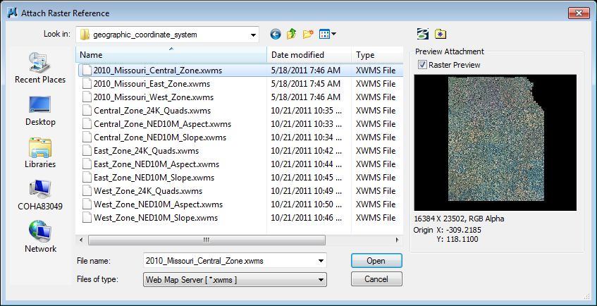
MicroStation                                                 Chapter 1 Geographic Tools

    1.1 Objectives
             •     Understand the use of the Geographic Tools and how they can be utilized in a
                   MicroStation file.

    1.2 Geographic Toolbar

Select Geographic Coordinate System                                                Play Camera Animation in Google Earth

        Global Positioning System (GPS)                                          Google Earth Settings

                 Export Google Earth (KML) File                               Follow Google Earth View

                      Capture Google Earth Image                          Synchronize Google Earth View
                                              Define Placemark Monument

    The Geographic Toolbar contains tools for interacting with a Global Positioning System (GPS)
    or Google Earth.

    This toolbar can be accessed from the Tools >> Geographic pull down in MicroStation.

    1.3 Select Geographic Coordinate System
    This tool is used to open the Geographic Coordinate System dialog, which is used to select a
    geographic coordinate system (GCS) from a library of predefined geographic coordinate
    systems.

    3/9/12                            Missouri Department of Transportation                                 1-1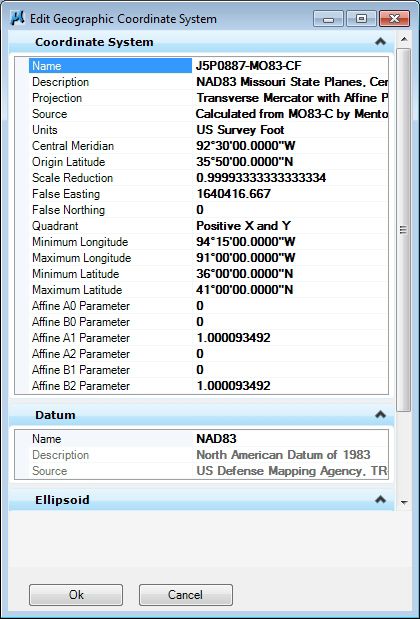
Chapter 1 Geographic Tools                                                      MicroStation

                 Details                                     Delete Geographic Coordinate System

               From Library                                Edit Reprojection Settings

                 From Placemarks                        From File

                       From Reference               To Reference

1.3.1 Details
This tool opens the Geographic Coordinate System Properties dialog box. It is used to display
the properties of a geographic coordinate system (GCS) that is attached to the MicroStation file.

1-2                           Missouri Department of Transportation                          3/9/12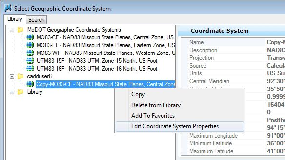
MicroStation                                           Chapter 1 Geographic Tools
1.3.2 From Library
This tool is used to select a geographic coordinate system (GCS) from MicroStation's library of
predefined geographic coordinate systems.

This is useful when:

   •     Existing data was drawn in a geographic coordinate system (for example a state plane or
         country grid coordinate system) and you want to make MicroStation aware of that GCS.
   •     Data is correctly drawn in one specified GCS, but you want to reproject that data to a
         different GCS.
   •     You want to designate the GCS for a new design file.

CADD Support has helped eliminate the confusion of which GCS to select from the predefined
library. We have provided a group called MoDOT Geographic Coordinate Systems which
contain the most commonly used coordinate systems for MoDOT projects.

Now since most projects use an modified coordinate system instead of the standard coordinate
system, you will need to copy and modified the standard coordinate system to match the applied
projection factor (grid to ground factor) for the project.

3/9/12                        Missouri Department of Transportation                           1-3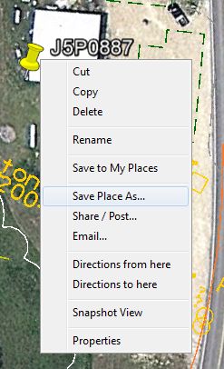
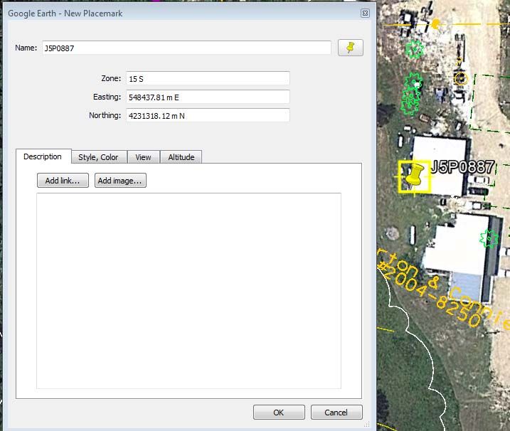
Chapter 1 Geographic Tools                                                     MicroStation
1.3.3 From Placemark
This tool allows you select a GCS defined by placemarks when using structure-centric
coordinate systems. Geographic placemarks, cells containing a name, longitude, latitude, and
altitude, indicate the geographic positioning of your design. The longitude, latitude, and altitude
fields specify the geographic position relative to the WGS 84 datum, which is the datum reported
by GPS devices and also used by Google Earth. The corresponding position in the design file is
specified by the placement point of the cell. The scale and rotation of the cell does not affect its
meaning as a geographic placemark.

At least two placemarks are required to calculate this GCS and should span the entire range of
interest. Placemarks are created using the Define Placemark Monument tool.

A Geographic Coordinate System calculated from placemarks is only as accurate as the
placemark data used to calculate it. If you use a calculated GCS to reference other geolocated
designs, errors could be cumulative. Therefore, treat measurements between features in
referenced designs as approximate.

1.3.4 From Reference
This tool is used to assign the GCS of an attached reference to the active model. You can use
references to orient your active model when the attached reference has a standard GCS specified
and has not been scaled or rotated, or when a reference with a computed Azimuthal Equal Area
GCS is attached without scaling (it can be moved and/or rotated).

If a geographic coordinate system, with an attached reference, has a geographic referencing
mode turned on, the reference cannot be used as a source for the GCS. Its position is calculated
from its GCS and the active model´s current GCS so selecting it as a source will not change the
current GCS. The Comment column provides the reason a particular attachment cannot be used
as a GCS source.

1-4                          Missouri Department of Transportation                           3/9/12
MicroStation                                             Chapter 1 Geographic Tools
1.3.5 To Reference
This tool is used to set the geospatial coordinate systems (GCS) of attached references based on
the GCS of the active model. If the GCS is selected from the standard library, it can be used to
set the GCS for coincident, unscaled, and unrotated reference attachments. If the GCS is
calculated from placemark monuments, it can be used to set the GCS for unscaled references.

1.3.6 From File
This tool allows you to apply a GCS from a model in another design file to your current file,
even if it is not attached as a reference.

1.3.7 Edit Reprojection Settings
This tool is used to specify the settings for reprojection. The tabs let you set the reprojection
settings differently for references and for the active model.

3/9/12                        Missouri Department of Transportation                                 1-5

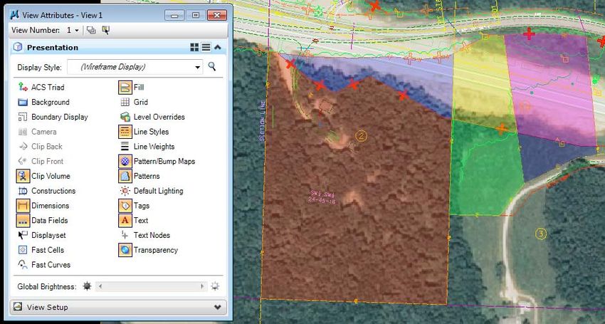
Chapter 1 Geographic Tools                                                      MicroStation
1.3.8 Delete Geographic Coordinate System
This tool deletes the geographic coordinate system attached to a MicroStation file.

It does not delete the geographic coordinate system from the MoDOT Geographic Coordinate
Systems library or the MicroStation predefined library.

1.4 Global Positioning System (GPS)
This tool is used to access a Global Positioning System (GPS) connected to your computer.

This tool will not be covered in detail in this class.

1.5 Export Google Earth (KML) File
This tool is used to export MicroStation geometry into a file format (KML) that Google Earth
can use to see the MicroStation geometry.

The settings that affect the export of a model are contained in the Google Earth Tools Settings
dialog.

The geometry is exported as WYSIWYG (what you see is what you get). That is, the view
attributes and level settings are taken from the active view. If Render Mode is set to From View,
in the Google Earth Export Settings dialog, then the display mode also is taken from the active
view. It is, therefore, important to set up the view as you would like it to display in Google Earth.
Output should be minimized to include only necessary data. The display of unnecessary levels
should be turned off. If text and dimensions are to be excluded from the output file then their
view attributes should be disabled.

Typically, Wireframe display mode is appropriate for 2D models, while for most 3D models it is
desirable to set the output display to Smooth.

1-6                            Missouri Department of Transportation                          3/9/12
MicroStation                                             Chapter 1 Geographic Tools

1.6 Capture a Google Earth Image
This tool will capture a Google Earth image that can be utilized in a MicroStation file. You can
only use this option in a 3d MicroStation file.

This tool will not be covered in detail in this class.

1.7 Define Placemark Monument
This tool is used to associate a geographical location to a Monument point in a model.

Placemark monuments are simply cells named “KmlPlacemark” with enter-data fields that
display the name, longitude, latitude, and altitude of the monument. The origin of the cell
represents the location of the placemark in the model. Multiple placemarks may be entered, and
you can use the Active Scale setting to control the size of the placemark cells.

This tool will not be covered in detail in this class.

1.8 Synchronize Google Earth View
This tool is used to have Google Earth navigate to the current MicroStation view. If Google
Earth is not open when the tool is used, it will be opened automatically.

As Google Earth supports only a limited camera model with a fixed lens length and restricts the
camera to pointing downward only, the Google Earth views will not always match the
MicroStation view exactly, but should provide a relatively good approximation for most views.

1.9 Follow Google Earth View
This tool is used to match the active MicroStation view to the current Google Earth view
location. This tool works only if the model's view location is geographically close to the current
Google Earth location.

3/9/12                         Missouri Department of Transportation                            1-7
Chapter 1 Geographic Tools                                                   MicroStation

1.10 Google Earth Tool Settings
This tool is used to control the settings and operation of the Google Earth tools. These options
determine how the KML gets created from the MicroStation drawing and if Google Earth opens
after exporting the MicroStation geometry to the KML file.

1.11 Play Camera Animation in
     Google Earth
This tool is used to play a camera animation in Google Earth. Camera animations only, are
supported.

After you have created a camera animation, you need only to geo-locate your model in some
way, such as by defining a Placemark. There is no need to export geometry to Google Earth.

This tool will not be covered in detail in this class.

1-8                            Missouri Department of Transportation                        3/9/12
MicroStation Chapter 1 Geographic Tools
1.12 Example 1-1
This example will show the process of creating a custom GCS with the projection factor (grid to
ground factor), attaching the custom GCS and exporting the MicroStation geometry to a file
format (KML) that Google Earth can use to visualize the geometry.
Information about this project:
• MicroStation geometry was placed using Missouri State Plane coordinates
• Project is located in the Missouri State Plane “Central” Zone
• Projection factor (grid to ground) for this project is 1.000093492
.
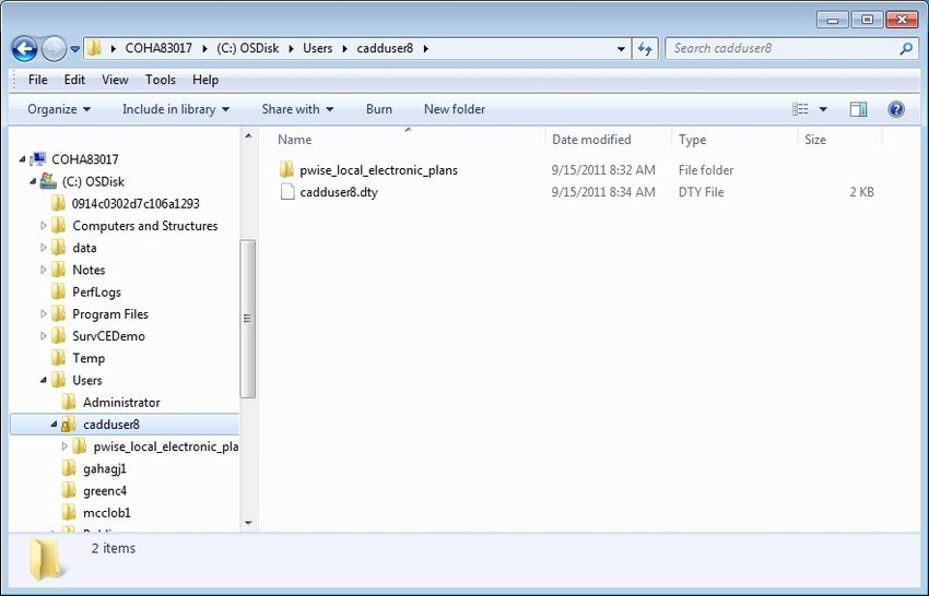
1. Open Windows Explorer and navigate to the following location:
C:/Programs Files/Bentley/MicroStation V8i (SELECTseries)/Map/coordinate/seed
Copy the file named seed.dty and place it under:
C:/users/cadduser##/seed.dty
Rename the copied seed file to your user id.
Example = cadduser##.dty
3/9/12 Missouri Department of Transportation 1-9Chapter 1 Geographic Tools MicroStation
2. In ProjectWise, open the following MicroStation file:
pwname:\\MoDOT\Documents\District CADD\Design\cadduser##\J5P0887\Plan_J5P0887.dgn
3. Go to the Applications pull down and activate Bentley Map. This needs to be done for us to
be able to edit the geographic coordinate system (GCS) and apply the appropriate projection
factor to it later on.
4. Click Yes when you get the prompt to save the changes to the file.
1-10 Missouri Department of Transportation 3/9/12MicroStation Chapter 1 Geographic Tools 5. Load the Geographics tool box under Tools >> Geographic and choose the Select Geographic Coordinate System tool. 3/9/12 Missouri Department of Transportation 1-11
Chapter 1 Geographic Tools                                                  MicroStation

6. Click on the From Library option in the Geographic Coordinate System dialog.

7. Under the MoDOT Geographic Coordinate Systems folder, right click over the Central
   Zone System and select the Copy option.

   Now right click over your user id folder (cadduser##) and Paste the coordinate system.

   This needs to be done so you can edit the coordinate system and apply the grid to ground
   factor for the project you are working on.

1-12                        Missouri Department of Transportation                        3/9/12
MicroStation                                          Chapter 1 Geographic Tools

8. Right click over the coordinate system under the cadduser## folder and select the Edit
   Coordinate System Properties option.

3/9/12                      Missouri Department of Transportation                           1-13
Chapter 1 Geographic Tools                                               MicroStation

9. In the Edit Geographic Coordinate System dialog, we will need to edit some items.

   Edit the following items:
      Name – whatever you wish to rename the system to
      Projection – Transverse Mercator to Transverse Mercator with Affine Processor
      Affine A1 Projector – input the grid to ground factor
      Affine B2 Projector – input the grid to ground factor

   Once those items have been edited, click OK.

1-14                       Missouri Department of Transportation                       3/9/12
MicroStation Chapter 1 Geographic Tools
10. You have now successfully created a custom geographic coordinate system that can be used
on any dgn file.
To apply the custom GCS, select the system and click OK.
You will now see the GCS applied to the dgn file.
Save the changes to the DGN file.
3/9/12 Missouri Department of Transportation 1-15Chapter 1 Geographic Tools MicroStation
1.13 Example 1-2
Once a coordinate system has been applied to a dgn file, you can use the Geographic tools in
MicroStation to create a KML file which can be used in Google Earth to show the MicroStation
geometry and graphics over the top of Google Earth imagery.
Note: Make sure Google Earth is installed on your machine prior to doing this operation.
1. In ProjectWise, open the following MicroStation file:
pwname:\\MoDOT\Documents\District CADD\Design\cadduser##\J5P0887\Plan_J5P0887.dgn
2. Load the Geographics tool box under Tools >> Geographic and select the Export Google
Earth (KML) File tool.
1-16 Missouri Department of Transportation 3/9/12MicroStation Chapter 1 Geographic Tools 3. You can create the KML file inside or outside of Projectwise. We will store the file inside ProjectWise for this example. Note: You can always export the KML file out of ProjectWise if necessary. Select No Wizard and then store the KML file to the desired folder in ProjectWise. Make sure the Name and File Name are the same. Save the KML file. 3/9/12 Missouri Department of Transportation 1-17
Chapter 1 Geographic Tools                                                  MicroStation

4. Once you click the Save icon, leave the computer alone.

   The conversion of the MicroStation file to a KML file may take a little time, depending on
   how large the microstation file is. When the KML is created, Google Earth will also open
   and zoom in to the area for the project according the view constraints of the MicroStation
   file.

   Tips:

   KML files can be used by anyone that has Google Earth install on their machine.

   When using Google Earth tools, levels and reference files can be turned off/on in the KML
   file. This is similar to how geometry can be displayed or not displayed in a dgn file.

1-18                        Missouri Department of Transportation                        3/9/12
MicroStation                                          Chapter 1 Geographic Tools
1.14 Exercise 1-1
Information about this project:
    • MicroStation geometry was placed using Missouri State Plane coordinates
    • Project is located in the Missouri State Plane “Central” Zone
    • Projection factor (grid to ground) for this project is 1.0001086

1. In ProjectWise, open the following MicroStation file:

         pwname:\\MoDOT\Documents\District CADD\Design\cadduser##\J5P0649\Plan_J5P0649.dgn

2. Since the DTY file is already created from the previous example, we don’t need to through
   the steps of copying and renaming it.

   Go to the Applications pull down and activate Bentley Map. This needs to be done for us to
   be able to edit the geographic coordinate system (GCS) and apply the appropriate projection
   factor to it later on.

3. Load the Geographics tool box under Tools >> Geographic.
   Choose the Select Geographic Coordinate System tool.

4. Click on the From Library option in the Geographic Coordinate System dialog.

5. Under the MoDOT Geographic Coordinate Systems folder, right click over the Central
   Zone System and select the Copy option.

   Now right click over your user id folder (cadduser##) and Paste the coordinate system.

   This needs to be done so you can edit the coordinate system and apply the grid to ground
   factor for the project you are working on.

6. Right click over the coordinate system under the cadduser## folder and select the Edit
   Coordinate System Properties option.

3/9/12                      Missouri Department of Transportation                             1-19
Chapter 1 Geographic Tools MicroStation
7. In the Edit Geographic Coordinate System dialog, we will need to edit some items.
Edit the following items:
Name – whatever you wish to rename the system to
Projection – Transverse Mercator to Transverse Mercator with Affine Processor
Affine A1 Projector – input the grid to ground factor
Affine B2 Projector – input the grid to ground factor
Once those items have been edited, click OK.
8. Apply the geographic coordinate system by selecting the system and click OK.
You will now see the GCS applied to the dgn file.
Save the changes to the DGN file.
9. Now we can go through the steps of creating the KML file so we can view MicroStation
geometry in Google Earth.
Load the Geographics tool box under Tools >> Geographic.
Select the Export Google Earth (KML) File tool.
10. Store the file inside ProjectWise for this exercise.
(Note: You can always export the KML file out of ProjectWise if necessary.)
Select No Wizard and then store the KML file to the desired folder in ProjectWise. Make
sure the Name and File Name are the same.
Save the KML file.
11. Once you click the Save icon, leave the computer alone and let MicroStation process the file
over into a KML file.
When the KML is created, Google Earth will open and zoom in to the area for the project
according the view constraints of the MicroStation file.
1-20 Missouri Department of Transportation 3/9/12Geographic Tools – Appendix MicroStation 1.1 Appendix This appendix will show the process using KML placemarks created in Google Earth and using those placemarks to bring MicroStation data over into Google Earth. This process can be used when projection factor is unavailable or when the MicroStation geometry doesn’t quite line up accurately with the Google Earth imagery when utilizing the Geographic Coordinate System method. . 1. Open Google Earth and zoom into the area for the project. Go to the Add pulldown and select Placemark. 3/9/12 Missouri Department of Transportation 1-1
MicroStation                                          Geographic Tools - Appendix

2. You will see the Untitled Placemark on the Google Earth imagery.

      Move the placemark to a common point that you can associate it with in the MicroStation file
      (example – corner of a building, known power pole, etc.)

      Now Name the placemark and click OK to place the placemark in Google Earth.

1-2                        Missouri Department of Transportation                    3/9/12
Geographic Tools – Appendix MicroStation 3. Once you have placed the placemark, you will need to save it so it can be used in MicroStation. Right click over the placed placemark and select the Save Place As…. option. Save it as a KMZ file to a desired location on the network. 3/9/12 Missouri Department of Transportation 1-3
MicroStation                                        Geographic Tools - Appendix

4. Now you are ready to use that KMZ file in a MicroStation file.

      Go the Tools pulldown, select Geographic and open the Geographic tools as a toolbox.

1-4                       Missouri Department of Transportation                   3/9/12
Geographic Tools – Appendix MicroStation 5. Select the Define Placmark Monument in the Geographic toolbox. In the Define Placemark Monument dialog, set the source to Google Earth Placemark File. Click the Browse icon in the dialog and navigate to the KMZ file that you created in Google Earth. Select the KMZ file and then click Done. You will now need to define the point for the origin of the placemark. Move the placemark to the same point as it was created in Google Earth and left click to place it in the MicroStation file. Note: Since we used the corner of a building for this example, use the MicroStation keypoint snap and snap to the corner of the building. Then left click to place the placmark in the dgn file. 3/9/12 Missouri Department of Transportation 1-5
MicroStation                                          Geographic Tools - Appendix

6. The MicroStation data is now ready to be used in Google Earth.

      Note: If you have a Geographic Coordinate System applied to the MicroStation file, it will
      need to be removed in order for the placed placemark to control how MicroStation creates
      the KML file that gets brought over to Google Earth

7. Select the Export Google Earth (KML) File tool in the Geographic tools.

1-6                        Missouri Department of Transportation                    3/9/12
Geographic Tools – Appendix MicroStation 8. You can create the KML file inside or outside of Projectwise. We will store the file inside ProjectWise for this example. Note: You can always export the KML file out of ProjectWise if necessary. Select No Wizard and then store the KML file to the desired folder in ProjectWise. Make sure the Name and File Name are the same. Save the KML file. 3/9/12 Missouri Department of Transportation 1-7
MicroStation                                          Geographic Tools - Appendix

9. Once you click the Save icon, leave the computer alone.

      The conversion of the MicroStation file to a KML file may take a little time, depending on
      how large the MicroStation file is. When the KML is created, Google Earth will also open
      and zoom in to the area for the project according the view constraints of the MicroStation
      file.

1-8                        Missouri Department of Transportation                     3/9/12
Geographic Tools – Appendix MicroStation 3/9/12 Missouri Department of Transportation 1-1
Chapter 2

                    Utilizing Web Map
                     Server Imagery
Chapter 2 ..........................................................................................................................................1
Utilizing Web Map Server Imagery.................................................................................................1
2.1 Objectives ..................................................................................................................................1
2.2 What is WMS Imagery?.............................................................................................................1
2.3 WMS Map Editor.......................................................................................................................2
2.4 Example 2-1 ...............................................................................................................................3
2.5 Exercise 2-1 .............................................................................................................................10

3/9/12                                Missouri Department of Transportation
MicroStation Chapter 2 Utilizing Web Map Server Imagery 2.1 Objectives Understand how to use available Web Map Server (WMS) imagery in a MicroStation file and utilizing that imagery to create project images for the project. 2.2 What is WMS Imagery? In the Raster Manager, you have the option to attach a WMS. WMS stands for Web Map Service Interface Standard. It provides a simple HTTP interface for requesting geo-registered map images from one or more distributed geospatial databases. A WMS request defines the geographic layer(s) and area of interest to be processed. The response to the request is one or more geo-registered map images (returned as JPEG, PNG, etc.) that can be displayed in a browser application. The interface also supports the ability to specify whether the returned images should be transparent so that layers from multiple servers can be combined or not. In Raster Manager, you can create new or attach existing Web Map Service files using New >WMS or Attach >WMS in the File menu. You can also manage WMS Servers using the Servers Manager dialog accessible through the WMS Map Editor dialog. 3/9/12 Missouri Department of Transportation 2-1
Chapter 2 Utilizing Web Map Server Imagery                                  MicroStation
2.3 WMS Map Editor
When you select the New >WMS in the Raster Manager dialog, you will get the option to create
new WMS map definition. This allows you to create a link to a certain web map server. The
available layers with the web map server lets you define what layers you want added to the map.

CADD Support has created some web map server links for MoDOT to use. These web map
server links are the latest imagery from the MSDIS (Missouri Spatial Data Information Service)
internet site. We have broken the web map server links by the Missouri State Plane Zones
(West, Central, East) and by the year the imagery was flown. CADD Support will periodically
check for newer imagery from MSDIS and add new links as needed.

For more information about creating a new web map link and available web map server links
already provided, please refer to the MicroStation help on this topic.

2-2                         Missouri Department of Transportation                        3/9/12
MicroStation                Chapter 2 Utilizing Web Map Server Imagery
2.4 Example 2-1
This example will show the process of attaching imagery through a web map server. We will
then create an image from the web map server imagery of the limits of the project.
.
1. In ProjectWise, open the following MicroStation file:

         pwname:\\MoDOT\Documents\District CADD\Design\cadduser##\J5P0887\Plan_J5P0887.dgn

2. Activate the Raster Manager. This can be loaded by the Raster Manager icon or under the
   File menu.

3/9/12                      Missouri Department of Transportation                            2-3
Chapter 2 Utilizing Web Map Server Imagery MicroStation 3. In the Raster Manager dialog, go to the File menu and select Attach - WMS. 2-4 Missouri Department of Transportation 3/9/12
MicroStation                  Chapter 2 Utilizing Web Map Server Imagery

4. The links to the web map server imagery are located outside of ProjectWise.

   Cancel out of the first dialog. Navigate to T:\standard\geographic_coordinate_system
   folder and attach the appropriate web map server (.xwms) that corresponds to the zone in
   which the project is located in.

   Use the 2010_Missouri_Central_Zone.xwms for the example.

   Click Open to attach it.

3/9/12                        Missouri Department of Transportation                           2-5
Chapter 2 Utilizing Web Map Server Imagery                                      MicroStation

5. Before you can attach the imagery, the Raster Attachment Options dialog will appear. This
   gives you the capability of modifying how you want the imagery to be attached.

      Since the web map server imagery has geographic intelligence to it, it is important that we
      change the “Geometry – Inherit GeoCS from Model” to Not Inherited. This allows the
      imagery to inherit the geographic coordinate system applied to the dgn file and should fall
      into place correctly with the MicroStation geometry.

      Finally select Attach to see the web map server imagery.

6. Once the web map server imagery has been loaded, you can create an image of the area for
   the project. In order to do this, you will need to open Descartes.

      Go to the Add-Ons menu and select Descartes to load the toolbar.
      Then click on the Descartes icon to load the application.

2-6                            Missouri Department of Transportation                          3/9/12
MicroStation Chapter 2 Utilizing Web Map Server Imagery 7. The Raster Manager dialog will open when you load the Descartes application. Under the Edit menu, select Merge. 8. Now use the options in the Merge tool to define the area for the image you want to create from the web map server imagery. For this example, we will use the Block option. 3/9/12 Missouri Department of Transportation 2-7
Chapter 2 Utilizing Web Map Server Imagery                                      MicroStation

9. Once you have defined the parameters for the image being created, you will need to review
   the options in the Merge Options dialog. There are a few options that you will need to
   change.

                 a. Element to Process: Rasters Only
                 b. Set Using: Pixel Size and DPI
                 c. Set the Pixel Size to 3. This will approximately match the pixel size of the
                    web map server imagery. Leave the DPI set to 300.

                                                a

                                                b

                              c

      Click Run when all the options are set the way you want it. Store the image to the desired
      location inside or outside of ProjectWise.

      For this example, store the image outside of ProjectWise in the following location:
      T:\de-proj\ArcGIS-CADD\cadduser##

      NOTE: The actual creation of the image may take a few minutes, depending on the size of
      the image being created. SO BE PATIENT and leave MicroStation alone while the image is
      being processed!!!!

2-8                            Missouri Department of Transportation                          3/9/12
MicroStation Chapter 2 Utilizing Web Map Server Imagery
10. You will now see the new image created from the web map server in the Raster Manager
dialog. The web map server that is still attached to the dgn file can be detached or turned off
in the view you have opened.
Save the changes to the DGN file.
3/9/12 Missouri Department of Transportation 2-9Chapter 2 Utilizing Web Map Server Imagery MicroStation
2.5 Exercise 2-1
1. In ProjectWise, open the following MicroStation file:
pwname:\\MoDOT\Documents\District CADD\Design\cadduser##\J5P0649\Plan_J5P0649.dgn
2. Activate the Raster Manager.
3. In the Raster Manager dialog, go to the File menu and select Attach – WMS.
4. Attach the appropriate web map server (*.xwms). Remember the links to the web map server
are located at T:\standard\geographic_coordinate_system.
Also make sure to change the “Geometry – Inherit GeoCS from Model” to Not Inherited
before you attach the web map server imagery.
5. Load Descartes in order to create the project image from the web map server imagery.
6. In the Raster Manager dialog, select Merge under the Edit menu.
Select the method you desire to use to create the image.
7. In the Merge Options dialog, change the options as needed to create the image.
For this exercise, store the image outside of ProjectWise in the following location:
T:\de-proj\ArcGIS-CADD\cadduser##
8. After the image has been created, detach or turn off the display of the web map server
imagery so just the newly created image shows in the dgn file.
Save the changes to the DGN file.
2-10 Missouri Department of Transportation 3/9/12Chapter 3
ArcGIS Data to
MicroStation
Chapter 3 ..........................................................................................................................................1
ArcGIS Data to MicroStation ..........................................................................................................1
3.1 Objectives ..................................................................................................................................1
3.2 Plan Geometry on Highway Plans .............................................................................................1
3.3 Referencing ArcGIS data in MicroStation .................................................................................1
3.4 Converting ArcGIS data into MicroStation Data.......................................................................2
3.5 Referencing ArcGIS data in MicroStation (From Reference File) ............................................3
3.6 Example 3-1 ...............................................................................................................................4
3.7 Example 3-2 ...............................................................................................................................7
3.8 Exercise 3-1 .............................................................................................................................10
3/9/12 Missouri Department of TransportationMicroStation Chapter 3 ArcGIS Data to MicroStation
3.1 Objectives
Show the process of taking ArcGIS data and utilizing the data in MicroStation. The process will
include converting ArcGIS data over into a MicroStation file. Also we will show using ArcGIS
data in MicroStation, but viewing the data as a referenced file.
3.2 Plan Geometry on Highway Plans
MoDOT utilizes a “modified” state plan coordinate system when laying out design projects.
Since the standard state plan coordinate system is not “on the ground”, the distances between
state plan points will not match what is in the field. These coordinates must be “modified” by a
certain factor so that they fit what’s on the ground. This factor is called “projection factor” or
“grid to ground” factor for a particular project.
The modified state plan coordinate system also allows for a higher degree of accuracy over the
length of the project since it applies the “projection factor” to all the surveyed points on the
project.
Projects are designed and constructed using the modified state plane coordinates because ground
distances are required. The district survey party can provided you the projection factor for a
project that you are working on.
Because the average elevation is included in the figuring of the “projection factor” calculation,
every project that is created will have a different “projection factor” applied to that project. This
creates issues when using MicroStation geometry within other applications like ArcGIS and vice
versa.
3.3 Referencing ArcGIS data in MicroStation
ArcGIS data can be viewed in a MicroStation file without the need to convert the UTM based
ArcGIS data over to a MicroStation file. This can be used when the ArcGIS data doesn’t need to
be edited and needs to be just viewed in the dgn file. This is done by using the Reference option
in MicroStation.
Basic Steps included:
• Using the Geographic tools to apply a custom state plan coordinate system to the
MicroStation file (explained in detail in Chapter 1).
• Opening the Reference option in MicroStation
• Attach the shapefile (*.shp) into the MicroStation file, just like if you were attaching a
dgn file to the master file.
3/9/12 Missouri Department of Transportation 3-1Chapter 3 ArcGIS Data to MicroStation MicroStation
• Change the Orientation when attaching the shapefile to Geographic – Reprojected.
This will reproject the ArcGIS data in the shapefile to the geographic coordinate system
that is applied to the MicroStation file and fall in the correct location on the file.
3.4 Converting ArcGIS data into MicroStation Data
ArcGIS data can also be easily converted over into MicroStation format. There are certain steps
that need to be done in order to convert the data because of the ArcGIS data normally being in
UTM coordinates and the MoDOT MicroStation data normally being in a modified state plan
coordinates.
Basic Steps included:
• Reprojecting the UTM coordinate based shapefile in ArcGIS to the correct Missouri State
Plan Zone coordinate system. The reprojected file is added back into ArcMap.
3-2 Missouri Department of Transportation 3/9/12MicroStation Chapter 3 ArcGIS Data to MicroStation
• In ArcMap, use the Export to CAD tool from within the Arc toolbox. This will create a
MicroStation file that will be in the State Plan Coordinate System.
• User can then take the newly converted file and use the Geographic toolbar to set the dgn
file coordinate system to the correct Modified State Plan Zone coordinate system.
3.5 Referencing ArcGIS data in MicroStation (From Reference File)
ArcGIS data that is referenced into a MicroStation file can be converted over into MicroStation
format. Doing this allows you to edit or use the data as MicroStation geometry. This also
eliminates the need to open ArcMap and using the Export to CADD tool to create a separate dgn
file of the ArcGIS data.
There are steps that need to be done in order to convert the data because of the ArcGIS data
normally being in UTM coordinates and the MoDOT MicroStation data normally being in a
modified state plan coordinates.
Basic Steps included:
• Using the Geographic tools to apply a custom state plan coordinate system to the
MicroStation file (explained in detail in Chapter 1).
• Opening the Reference option in MicroStation
• Attach the shapefile (*.shp) into the MicroStation file, just like if you were attaching a
dgn file to the master file.
• Change the Orientation when attaching the shapefile to Geographic – Reprojected.
This will reproject the ArcGIS data in the shapefile to the geographic coordinate system
that is applied to the MicroStation file and fall in the correct location on the file.
• Select the “Merge to Master” option in the Reference dialog to extract the data out of the
shapefile and place it as MicroStation geometry for you to edit or use, if necessary.
3/9/12 Missouri Department of Transportation 3-3Chapter 3 ArcGIS Data to MicroStation MicroStation
3.6 Example 3-1
This example will demonstrate how to take an ArcGIS shapefile and use it as a reference file in a
MicroStation file.
1. In ProjectWise, open the following MicroStation file:
pwname:\\MoDOT\Documents\District CADD\Design\cadduser##\J5P0887\Plan_J5P0887.dgn
2. Open the Reference dialog. Under the Tools menu, select the Attach option. This will
allow you to navigate to the stored shapefiles.
3-4 Missouri Department of Transportation 3/9/12MicroStation Chapter 3 ArcGIS Data to MicroStation 3. Once in the Attach Reference dialog, click Cancel. Now you can navigate to the location on the network where you have the shapefiles at. For this example, the shapefiles are stored in the following location: T:\de-proj\ArcGIS-CADD\cadduser## If the shapefiles don’t show up in the list, change the File of type filter to Shapefiles (*.shp). Note: ArcGIS shapefiles need to be stored outside ProjectWise. This is because shapefiles use other associated files with it. When the shapefiles and other associated files are stored in ProjectWise, MicroStation just tries to attach the shapefile and doesn’t know how to handle the other files associated to the shapefiles. 3/9/12 Missouri Department of Transportation 3-5
Chapter 3 ArcGIS Data to MicroStation                                       MicroStation

4. Before attaching the shapefiles, you will need to change the attachment method on how the
   shapefile gets attached to the dgn file.

      Within the Attach Reference dialog, change the Attachment Method to Geographic –
      Reprojected.

      Using the Geographic – Reprojected attachment method allows MicroStation to take the
      coordinate system applied to the shapefiles being attached and reprojects them to the
      geographic coordinate system applied to the MicroStation file.

      Click Open when you are ready to attach the shapefiles.

5. You should now see the attached shapefiles in the MicroStation file.

      Save the changes to the dgn file.

3-6                           Missouri Department of Transportation                      3/9/12
MicroStation Chapter 3 ArcGIS Data to MicroStation 3.7 Example 3-2 This example will demonstrate how to take a referenced ArcGIS shapefile and extract the geometry out of the shapefile and make it into active geometry in the MicroStation file. 1. Activate the Reference dialog. Select the shapefiles in the reference dialog you want to “merge” into the active dgn file. 2. Under the Tools menu, select the Merge to Master option. 3/9/12 Missouri Department of Transportation 3-7
Chapter 3 ArcGIS Data to MicroStation                                      MicroStation

3. You will be prompted in the status bar to Select View to Merge.

      Left click anywhere in the view window.

4. An Alert dialog will appear telling you how many reference files you have selected to merge
   into the active file.

      Click OK in the dialog.

3-8                             Missouri Department of Transportation                   3/9/12
MicroStation Chapter 3 ArcGIS Data to MicroStation
5. Once you click OK, it will then take the selected reference files and merge them into the
active file. The geometry is now MicroStation geometry that can be edited or modified.
Save the changes to the dgn file.
Tip:
When you merge shapefiles into a MicroStation file, it will automatically put the shapefile
geometry on the following geometry attributes:
Level – Default
Color – 0
Style – 0
Weight – 0
If you need to keep the geometry separated out for each corresponding shapefile, one thing
that can be done is to merge one shapefile at a time. After merging one shapefile, use the
Select By Attribute and select the Default level. This will select everything that is on that
level. Then you can use the Change Element Attributes tool to change the selected
geometry to the desired attributes (level, color, style, weight) you wish.
This operation can be done for each shapefile so the geometry on the merged shapefile is still
broken out in the file.
3/9/12 Missouri Department of Transportation 3-9Chapter 3 ArcGIS Data to MicroStation MicroStation
3.8 Exercise 3-1
1. In ProjectWise, open the following MicroStation file:
pwname:\\MoDOT\Documents\District CADD\Design\cadduser##\J5P0649\Plan_J5P0649.dgn
2. Attach the following shapefiles to the MicroStation file. Make sure you change the
attachment method to Geographic – Reprojected before attaching the shapefiles.
D5_Cities.shp
D5_Routes.shp
Wetlands.shp
The files are located under: T:\de-proj\ArcGIS-CADD\cadduser##
3. Now take each referenced shapefile and merge them into the active dgn file.
Merge each shapefile separately. After merging a shapefile, change the attributes of the
merged shapefile geometry to the following:
D5_Cities.shp - Level = Scratch 1, Color = 2
D5_Routes.shp - Level = Scratch 2, Color = 4
Wetlands.shp - Level = Scratch 3, Color = 3
4. Save the changes to the dgn file.
3-10 Missouri Department of Transportation 3/9/12Chapter 4
Transparency
Chapter 4 ..........................................................................................................................................1
Transparency ....................................................................................................................................1
4.1 Example 4-1 ...............................................................................................................................1
4.2 Example 4-2 ...............................................................................................................................5
4.3 Exercise 4-1 ...............................................................................................................................8
3/9/12 Missouri Department of TransportationMicroStation Chapter 4 Transparency
4.1 Example 4-1
This example will demonstrate how to create transparent shapes in MicroStation, without having
to use Descartes like you use to have to do in the past.
Of course, there are many ways of creating filled shapes in MicroStation, but these instructions
will give you an overall understanding of how to apply the transparency to the filled shapes.
.
1. In ProjectWise, open the following MicroStation file:
pwname:\\MoDOT\Documents\District CADD\Design\cadduser##\J5P0887\Plan_J5P0887.dgn
2. Determine the area you want to have filled. Use the Create Region tool or Place Shape tool
and create the filled shape.
When using either tool, set the fill type to Opaque and the fill color to the desired color.
3/9/12 Missouri Department of Transportation 4-1Chapter 4 Transparency MicroStation
3. Once you have the filled shapes created, you can now apply the transparency to them.
Select the Change Element Attributes tool. Check the Transparency toggle in the tool and
then determine what percent of transparency you wish for the filled shape.
Once those options are selected, go through the file and apply the transparency to the desired
filled shapes.
4-2 Missouri Department of Transportation 3/9/12MicroStation Chapter 4 Transparency 4. After applying the transparency to the shapes, you will probably notice that nothing visually happens to the filled shapes. In order to display the transparency on the filled shapes, open the View Attributes tool (under Settings pulldown or the first icon in the View Tools) 3/9/12 Missouri Department of Transportation 4-3
Chapter 4 Transparency                                                           MicroStation

5. Toggle on the Transparency option the View Attributes dialog.

      If the transparency was applied correctly in the previous steps, the filled shapes should look
      something like the image below:

6. Once you have the desired transparent shapes, MAKE SURE you go back and change the
   Transparency option in the Change Attribute tool back to 0.

      This has to be done so you don’t accidentally start creating geometry (like edge of pavement
      line, guardrail line, etc.) and having that transparency applied to the lines.

4-4                            Missouri Department of Transportation                           3/9/12
MicroStation Chapter 4 Transparency
4.2 Example 4-2
This example will demonstrate how to apply a transparency to a raster image and/or web map
server in order to see through to another raster image and/or web map server.
1. In ProjectWise, open the following MicroStation file:
pwname:\\MoDOT\Documents\District CADD\Design\cadduser##\J5P0887\Plan_J5P0887.dgn
2. Open the Raster Manager and attach the following web map servers:
2010_Missouri_Central_Zone.xwms
Central_Zone_NED10M_Slope.xwms
Central_Zone_24K_Quads.xwms
3/9/12 Missouri Department of Transportation 4-5Chapter 4 Transparency MicroStation
3. In the Raster Manager, the order of the raster images or web map servers is important. This
is because MicroStation looks at the order of raster images or web map servers attached and
uses the last one in the list as the “top” raster image or web map servers that will display in
the MicroStation view.
For this example, we want the Central_Zone_24K_Quads.xwms to be at the bottom of the
list so it will be the “top” one displayed in the MicroStation view. This will also allow us to
apply the transparency to this web map server and we will able to see the next web map
server imagery through the Central Zone 24K Quads web map server.
For this example, reorder the web map servers as shown in the image below. This is done by
simply selecting the raster image or web map server in the Raster Manager dialog. Then
hold your left mouse button down and move it up or down to the desired spot so the order of
the files is the way you want it.
4-6 Missouri Department of Transportation 3/9/12MicroStation Chapter 4 Transparency 4. Now we can go through and apply the transparency to the Central Zone 24k Quads web map server. In the Raster Manager dialog, select the Central_Zone_24K_Quads.xwms. Right click over the selected web map server and choose the Transparency option. 5. In the Transparency dialog, first toggle on the Transparent option. You will now have the options to apply the percentage of transparency. In the All Colors option, type in or move the bar to the desired percentage of transparency for the selected web map server. Once that percentage is set, click OK. You should see the web map server imagery update to reflect the transparency applied to it. You also will be able to see the next web map server imagery or raster image (that has the display turned on) through the transparent web map server or raster image. Save changes to the file. 3/9/12 Missouri Department of Transportation 4-7
Chapter 4 Transparency                                                               MicroStation
4.3 Exercise 4-1

1. In ProjectWise, open the following MicroStation file:

           pwname:\\MoDOT\Documents\District CADD\Design\cadduser##\J5P0649\Plan_J5P0649.dgn

2. Determine the area you want to have filled. Use the Create Region tool or Place Shape tool
   and create the filled shape. Set the fill type to Opaque and select the desired fill color.

      For this exercise, just pick out 4 – 6 areas for creating the filled shapes.

3. Select the Change Element Attributes tool. Check the Transparency toggle in the tool and
   then determine what percent of transparency you wish for the filled shape.

      Go through the dgn file and apply the transparency to the filled shapes.

4. To display the transparency on the filled shapes, open the View Attributes tool (under
   Settings pulldown or the first icon in the View Tools).

5. Toggle on the Transparency option the View Attributes dialog to see the transparent shapes.

6. Once you have the desired transparent shapes, MAKE SURE you go back and change the
   Transparency option in the Change Attribute tool back to 0.

      This has to been done so you don’t accidentally start creating geometry (like edge of
      pavement line, guardrail line, etc.) and having that transparency applied to the lines.

      Save the changes to the dgn file.

4-8                              Missouri Department of Transportation                          3/9/12
Chapter 5
HMR Plotting
Chapter 5 ..........................................................................................................................................1
HMR Plotting ...................................................................................................................................1
5.1 Objectives ..................................................................................................................................1
5.2 HMR Plotting .............................................................................................................................1
5.3 MoDOT Descartes dialog ..........................................................................................................1
5.4 Print dialog .................................................................................................................................3
5.4.1 Print Attributes ..................................................................................................................4
5.4.2 Raster Options ...................................................................................................................5
5.4.3 Print Icons .........................................................................................................................5
5.5 Example 5-1 ...............................................................................................................................7
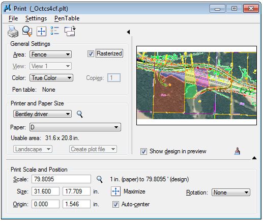
3/9/12 Missouri Department of TransportationMicroStation Chapter 5 HMR Plotting through Descartes 5.1 Objectives Understand the use of the HMR plotting in Descartes and the options and settings that are contained within the HMR plotting routine. 5.2 HMR Plotting HMR plotting is a plotting routine contained in the Descartes toolbar. This plotting routine gives you the flexibility to modify settings (print quality, line weights, transparency, etc.) before sending it to the print. You don’t have these options using the standard MoDOT plotting routine. In addition, MicroStation files that have images attached to it will print out in better quality using the HMR plotting vs. the standard MoDOT plotting routine. To load the HMR plotting routine, you need to load the Descartes toolbar first. This is located under the Add-Ons menu in MicroStation. 5.3 MoDOT Descartes dialog After selecting the HMR plotting icon, a series of dialog boxes will appear defining where you are sending the plot to and what print attributes you want for the print. The first dialog in the series will be the MoDOT Descartes plotting dialog. In here, you have the options of what plotter, location, papersize, color, etc. you desire for the print. Plotter - select the plotter you desire to send the print to Location - select the location for the print Papersize - select the paper size that the plotter can handle Color - select if you want the print to be in color or black and white 3/9/12 Missouri Department of Transportation 5-1
Chapter 5 HMR Plotting through Descartes                                      MicroStation

When you have the Plotter set to PDF, you will need to define where you want to store the PDF
file. This is the PDF File Destination and it allows you to select the location of where you desire
to store the PDF file from the MicroStation file. Use the Browse icon and then you can store the
file within ProjectWise or to a network location.

The Open File Destination Folder toggle will open up the folder when the PDF gets created. It
will open up Windows Explorer to the location of where you stored the file.

This toggle doesn’t work when you store the PDF file in ProjectWise though.

5-2                          Missouri Department of Transportation                          3/9/12
MicroStation                   Chapter 5 HMR Plotting through Descartes
5.4 Print dialog
After defining the options in the MoDOT Descartes dialog (previous dialog), the next dialog box
that will appear will be the Print dialog. This has many options and settings on how you can
define the appearance of the print when it is plotted out

For MoDOT purposes, we will go over the options and settings that needed to be reviewed
before sending it to the printer.

3/9/12                      Missouri Department of Transportation                           5-3
Chapter 5 HMR Plotting through Descartes                                     MicroStation
5.4.1 Print Attributes
The Print Attributes is located in the Settings menu. In here, you can define what you want to
show up on the plot or not show up on the plot.

Review these options before printing the sheet.

5-4                          Missouri Department of Transportation                         3/9/12
MicroStation                          Chapter 5 HMR Plotting through Descartes
5.4.2 Raster Options
Another option that should be reviewed is the Raster Options. This allows you to modify the
raster images attached to the file like changing the raster quality, brightness, contrast, etc. for the
plot.

5.4.3 Print Icons
Also in the Print dialog are some icons for quick access to certain functions.

                              Print                                Update from View
                            Preview                               Print Attributes
                                         Maximize Print Size

3/9/12                         Missouri Department of Transportation                                5-5
You can also read