Open-Channel Solid State Drives Specification - LightNVM
←
→
Page content transcription
If your browser does not render page correctly, please read the page content below
Open-Channel
Solid State Drives
  Specification
              Revision 2.0

            January 29, 2018

 Please send comments to mb@lightnvm.io
License
By making a suggestion, providing feedback or any other contribution to the Open-Channel SSD
specification (each, a “Contribution”), you (on behalf of yourself, your employer and its affiliates)
hereby grant implementers of the specification the following license: A worldwide, fully-paid,
royalty-free, irrevocable, perpetual license under all intellectual property rights owned by you, your
employer and its affiliates to use, make, have made, import, sell, offer to sell any products or
services using or incorporating any Contribution and to distribute, prepare derivative works, copy
and display any Contribution in connection with any products or services using or incorporating
any Contribution, on a standalone basis or as incorporated into the Open-Channel SSD
specification or necessary to its implementation and to incorporate the Contribution into the Open-
Channel SSD specification without restriction of any kind. By submitting any Contribution to this
specification, you represent and warrant that you have the right to grant the foregoing license (on
behalf of yourself, your employer and its affiliates).
Legal Disclaimer
All product names, trademarks, registered trademarks, and/or service marks may be claimed as
the property of their respective owners.
1Table of Contents
1. Introduction .......................................................................................................................... 3
1.1 Definitions......................................................................................................................... 4
1.1.1 physical media ........................................................................................................... 4
1.1.2 open-channel solid state drive .................................................................................... 4
1.1.3 parallel unit (PU) ........................................................................................................ 4
1.1.4 group.......................................................................................................................... 4
1.1.5 chunk ......................................................................................................................... 4
1.1.6 logical block ............................................................................................................... 4
1.1.7 physical page address command set ......................................................................... 4
1.1.8 write unit .................................................................................................................... 4
1.2 Theory of Operation .......................................................................................................... 5
1.2.1 Overview .................................................................................................................... 5
1.2.2 Open-Channel SSD Representation........................................................................... 6
1.2.3 Address Representation ............................................................................................. 6
1.2.4 Chunk Model .............................................................................................................. 7
1.2.4 Chunk Access Rules .................................................................................................. 8
1.2.5 Wear-leveling ............................................................................................................11
2. Physical Page Address Command Set ..............................................................................12
2.1 Admin Commands.......................................................................................................12
2.1.1 Geometry ..................................................................................................................12
2.1.2 Get Log Page - Chunk Information ............................................................................15
2.1.3 Feature Specific Information .....................................................................................18
2.2 I/O Commands ................................................................................................................20
2.2.1 Vector Commands ....................................................................................................20
2.2.2 Vector Chunk Reset Command and Response .........................................................21
2.2.3 Vector Chunk Write Command and Response ..........................................................22
2.2.4 Vector Chunk Read Command and Response ..........................................................23
2.2.5 Vector Chunk Copy Command and Response ..........................................................24
2.4 Asynchronous Event Information .....................................................................................26
2.4.1 Vendor Specific Notification (Log identifier D0h)........................................................26
21. Introduction
NVM Express (NVMe) 1.3 and prior revisions define a register-level interface for host software to
communicate with a non-volatile memory subsystem over PCI Express (i.e., NVMe over PCIe).
This specification defines the Physical Page Addressing Command Set extension to the NVMe
specification. It enables Solid State Drives (SSDs) to expose their internal parallelism and allows
the host to perform data placement and I/O scheduling that has previously been handled by the
SSD.
31.1 Definitions
See the NVMe 1.3 specification for additional definitions.
1.1.1 physical media
The underlying physical non-volatile memory that is attached to the NVMe controller. Including,
but not limited to NAND flash.
1.1.2 open-channel solid state drive
Refers to Solid State Drives that conforms to this specification.
1.1.3 parallel unit (PU)
Refers to a single parallel unit within the storage media. A single SSD may contain tens or
hundreds of these parallel units.
1.1.4 group
Refers to a set of parallel units that share the same transfer bus within the open-channel SSD.
1.1.5 chunk
Refers to a set of contiguous logical blocks. The blocks shall be written sequentially within the
chunk. A chunk is the smallest range of logical blocks that can be reset as a unit.
1.1.6 logical block
The smallest addressable data unit for Read and Write commands. This takes on the meaning
from the NVMe specification, and does not represent a physical flash block.
1.1.7 physical page address command set
Name of the command set. Physical references to the storage hierarchy (groups & PUs). Mapping
of logical block addresses (LBA) to physical media addresses is up to the device implementation
and must be media-independent to the host.
1.1.8 write unit
A write unit is the smallest number of logical blocks that shall be written at a time.
41.2 Theory of Operation
1.2.1 Overview
This specification defines a class of SSDs named Open-Channel SSDs. They are different from
traditional SSDs in that they expose the internal parallelism of an SSD and allow the host to
manage them. Maintaining the parallelism on the host enables benefits such as I/O isolation,
predictable latencies, and software-defined non-volatile memory management, that scales to
hundreds or thousands of workers per terabyte.
I/O Isolation
I/O isolation is provided by dividing the capacity of the SSD into many logical units that map to
the parallel units of the device. At the physical media level, the PUs are isolated from one
another. By dividing the device into its parallel unit's boundaries, the host can avoid the noisy
neighbor problem for massively multi-tenant applications.
Predictable latency
Predictable latency is achieved by giving the host control over when, where and how I/O
commands are submitted to the drive. The I/O isolation between the parallel units provides
achieving predictable latency, as I/O to one parallel unit should not impact I/O to another parallel
unit, while synchronously issuing I/O commands allows the host to reason when a parallel unit is
active or not.
Host-Managed Non-Volatile Memory Management
Enables the host to control data placement, I/O scheduling and implement tight integrations with
file-systems and applications.
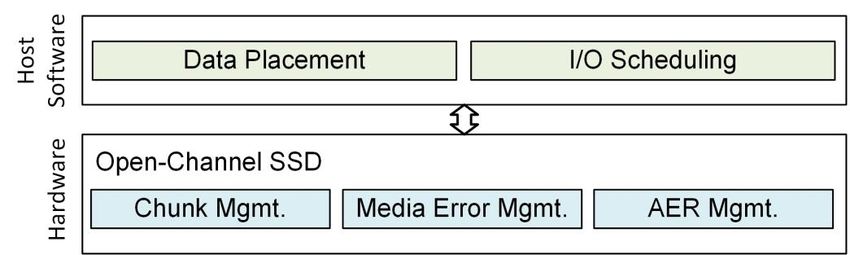
Figure 1 shows the division of responsibility between the host and SSD. The host implements
generic mapping functionality: data placement, I/O scheduling and garbage collection; and can
expose a host defined storage interface (block device, object store, key-value, or any other type
of interface) to higher level applications. The SSD manages media-centric metadata, error
handling, scrubbing and wear-leveling and exposes an abstract interface for the host to control.
Figure 1: Responsibility of an Open-Channel SSD
51.2.2 Open-Channel SSD Representation
Figure 2 shows the internal representation of an open-channel SSD. Its structure is divided into
Groups, Parallel Units (PUs), Chunks, and Logical blocks.
Figure 2: Logical parallelism in an SSD
A group is a shared bus within the Open-Channel SSD, where bandwidth and transfer overhead
(PCIe, controller, DRAM; no blocking between read/write/reset) are shared between the parallel
units attached. A parallel unit is the unit of parallelism within the SSD, and its access is fully
independent of other parallel units. For example, if a write is issued to one parallel unit, another
parallel unit should not be busy, other than the delay introduced by sharing the same group.
Note that the representation is not necessarily the physical media attachments and can be a
logical representation.
Within Parallel units, there is a set of chunks. The chunks represent a linear range of logical
blocks. The chunks require that writes to them are issued sequentially and that a chunk is reset
before being written to again.
1.2.3 Address Representation
An Open-Channel SSD exposes a hierarchical representation of its logical blocks. This allows
the host to control which parallel unit is accessed independently from other parallel units. The
SSD firmware should not be optimized for any particular workload, as the host will manage
access to the parallel units and which chunks are accessed, such that the host can manage the
SSD characteristics with respect to parallelism.
The logical representation covers groups, PUs, chunks, and logical blocks. The various fields
are represented through a NVMe LBA. The fields are laid out beginning with groups at the most
significant bits, followed by PU, chunk, and logical blocks. See Figure 3 for a representation.
The size of each field is defined by the Geometry command.
6Figure 3: LBA Encoding
1.2.4 Chunk Model
This section describes the access rules for chunks. There are three I/O command types: Read,
Write and Reset. Data can be retrieved from a chunk by issuing reads. The minimum read size
is the logical block size. To write data, the host must write sequentially within a chunk, and each
command must fulfill the minimum write unit size. After a chunk is fully written, the chunk must
be reset by the host before it can be written again.
The chunk fields are shown in Figure 4. Each chunk maintains at least four fields: A start LBA
(SLBA), number of logical blocks (NLB), write pointer (WP), and chunk state (CS). They are
used to communicate the start of the chunk, its size, when a chunk is open, and the number of
logical blocks that have been written within a chunk.
Figure 4: Chunk Fields
The state field defines the state of a chunk. It can be either (i) free, (ii) open, (iii) closed, or (iv)
offline. During the lifetime of a chunk, it cycles through (i-iii), whereas, at the end of its lifetime,
its state becomes (iv) offline. Figure 5 shows the lifetime of a chunk, beginning from the free
state.
If write pointer equals 0, the chunk state is “free”, and if the write pointer is greater than zero
and less than SLBA + NLB, the chunk is “open” or “closed”. If WP = SLBA + NLB, the chunk is
“closed”. The state of a chunk is implicitly set to "open" when writing to it. Additionally, if the
controller namespace supports "multiple resets during free state", the chunk may be reset
multiple times while in its “free” state.
An “open” chunk allows reads up till the write pointer. However, if “Cache Minimum Write Size
Units” is active. Reads are only allowed up to “WP - the cached units”. When a chunk is in its
“closed” state, logical blocks up till the write pointer address can all be accessed.
The final state of a chunk is “offline”, and only happens once the chunk is no longer usable. The
“offline” state for a chunk may occur after reset that reports an “offline chunk” status. When
entering the “offline” state, it can no longer be used by the host. The host knows the probability
of getting to an “offline” state by monitoring the wear-level index reported for each chunk.
7Figure 5: Chunk State Diagram
1.2.4 Chunk Access Rules
Depending on the state of a chunk, some operations may be valid or invalid. The rules below
describe the input and response, and if it is a valid operation. An invalid operation may not
necessarily lead to an error but may return predefined data. There are rules defined for the
read, write, and reset I/O commands, which are the commands that access the chunks.
Read Access Rules
All reads are valid to the controller. If data is not available, the data to be returned are
predefined by the Deallocate Logical Block Features (DLFEAT) field in the NVMe 1.3 Identify
NVM Command Set data structure. The read access rules are defined in Figure 6.
For controllers that have the "Cache Minimum Write Size Units (MW_CUNITS)" set in the
Geometry command, and has open chunks, the open blocks data is not available until either the
chunk has been closed or the Write Pointer has advanced at least MW_CUNITS blocks beyond
the LBA being read.
If the controller has Error Recovery (Section 2.1.3.1) set, the “Predefined data is returned” will
instead return an error.
8Figure 6: Read Access Rules
Operation Chunk Valid Note
State
Read Free Yes Predefined data is returned. Completion entry status is
“Success”.
Read < (WP LBA - Open, Yes Data read and returned. Completion entry status is
MW_CUNITS) Closed “Success”.
Read >= WP LBA Open, Yes Predefined data is returned. Completion entry status is
Closed “Success”.
Read between (WP - Open Yes Predefined data is returned. Completion entry status is
MW_CUNITS) LBA and “Success”.
WP LBA
Read Offline Yes Predefined data is returned. Completion entry status is
“Success”.
Read non-existing LBA N/A Yes Predefined data is returned. Completion entry status is
“Success”.
Write Access Rules
The writes to the chunk must be sequential. This introduces several conditions where writes are
invalid. For example, writes that skip LBAs are invalid, as are writes that address LBAs smaller
than the Write Pointer within a chunk without first resetting the chunk. These are in addition to
other invalid cases, such as writes that are to LBAs that do not exist (out of the chunk's bounds)
and writes that are to an offline chunk. The write access rules are defined in Figure 7.
Figure 7: Write Access Rules
Operation Chunk State Valid Note
Write at SLBA Free Yes Data written to media. Completion entry status is
“Success”.
Device action:
1) WP increased with logical blocks written.
2) Chunk state is marked open.
Write at SLBA + WP Open Yes Data written to media. Completion entry status is
address “Success”.
Device action:
1) WP increased with logical blocks written.
Write such that WP = Open Yes Data written to media.
SLBA + NLB
Device action:
1) WP increased with LBAs written.
2) Chunk state is marked closed.
Write fail (Write Next Free / Open Yes Data is not written. Completion entry status is “Write Next
Unit) Unit”.
9Device action:
1) WP increased with logical blocks that would
have been written.
Write fail (Chunk Early Free / Open Yes Data not written. Completion entry status is “Chunk Early
Close) Close”.
Device action:
1) WP not increased.
2) Chunk state is marked closed.
Host recovery
1) Host may read up til WP.
Write > WP or Write < Open No Completion entry status is “Out-of-order Write”.
WP
Write Closed No Completion entry status is “Write Fault”.
Write Offline No Completion entry status is “Write Fault”.
Write non-existing LBA N/A No Completion entry status is “Write Fault”.
Reset Access Rules
A chunk reset can be issued when chunk state is closed. Additionally, if the controller
namespace supports "multiple resets during free state", the chunk may also be reset if it is in
the free state. The reset access rules are defined in Figure 8.
Figure 8: Reset Access Rules
Operation Chunk State Valid Note
Reset Free Yes/No If single reset is supported (default):
- Completion entry status is “Invalid Reset”.
Prevents double resets.
If multiple resets are supported:
- The chunk state is either set to free or offline. If
offline, the reset completion status “Offline
Chunk” is returned.
Reset Open No Completion entry status is “Invalid Reset”. Prevents
double resets.
Reset Closed Yes Chunk state is either set to free or offline. If offline, the
reset completion status “Offline Chunk” is returned.
Reset Offline No Completion entry status is “Offline Chunk”. The chunk is
already offline.
Reset non-existing LBA N/A No Completion entry status is “Invalid Reset”. There is no
corresponding chunk to reset.
101.2.5 Wear-leveling
Since actions taken to distribute wear evenly affect the drive’s isolation guarantee, maintaining
an even wear across chunks is the responsibility of the host.
For each chunk descriptor, a relative wear-level index is provided. It communicates the relative
wear of a given chunk. The value is monotonically increasing from 0 to 255. 0 signals that a
chunk is in new condition, and 255 signals that the chunk is end-of-life.
If the geometry command specifies a wear-level index delta threshold, the host should wear-
level all chunks evenly, such that the wear-level index for all chunks does not exceed plus or
minus the wear-level index delta value across all chunks. For example, if the threshold is 10 and
the average chunk wear is 100, the wear-level index delta is allowed to be within the range of
90-110. If host does not wear-level index delta according to the threshold the device may signal
it through a Chunk Notification Log event.
112. Physical Page Address Command Set
This section defines the specification of the Physical Page Address command set. It consists of
Admin and I/O commands. The admin commands are used to communicate the geometry of the
device and chunk state, while the I/O commands are used to read, write and copy data, and
reset chunks.
All commands conform to the regular NVMe command structure, as described in the NVMe 1.3
specification, under the section “Submission Queue Entry – Command Format”. Non-specified
fields follow the standard submission queue entry fields.
2.1 Admin Commands
The command set defines two admin commands to enable the host to enumerate the
configuration of the device and read individual chunk state. The opcodes are defined in Figure
9.
Figure 9: Opcodes for Admin Commands
Opcode Opcode Opcode Namespace
(07) (06:02) (01:00) Identifier
NVMe Opcode O/M Used Command
Generic Function Data
Transfer
1b 110 00b 10b E2h M Yes Geometry
0b 000 00b 10b 02h M Yes Get Log Page - Chunk Information
0b 000 10b 01b 09h M Yes Set Features - Media Feedback
0b 000 10b 10b 0Ah M Yes Get Features - Media Feedback
2.1.1 Geometry
For the host to issue I/O commands to the device, the boundaries of groups, parallel units, and
chunks must be known. The geometry command communicates these boundaries to the host.
Command Submission
The following NVMe command may be used to request geometry. Refer to Figure 11 in the
NVMe 1.3 specification for command description. The data buffer to store the geometry in is
defined in Figure 10.
12Figure 10: Device Geometry - Data Pointer
Bit Description
127:00 Data Pointer (DPTR): This field specifies where data is transferred to.
Command Completion
On command completion, the controller must post a completion queue entry to the Admin
Completion Queue indicating the status for the command.
Status Field and Status Code follow the error codes defined in NVMe Specification Section 2.3.
On success, the data structure defined in Figure 11 is returned.
Figure 11: Device Geometry Data Structure
Byte Description
0 Major Version Number (MJR): Major revision identification. Valid revisions are:
Value Description
1 Implements revision 1.2 of the specification.
2 Implements revision 2.0 of the specification. The revision is not
backwards compatible with revision 1.2.
1 Minor Version Number (MNR): Minor revision identification.
7:2 Reserved
15:8 LBA Format (LBAF): See Figure 12.
19:16 Media and Controller Capabilities (MCCAP):
Bits Description
31:2 Reserved
1 If set to ‘1’ the namespace supports multiple resets when a chunk is in
its free state.
0 If set to ‘1’, the namespace supports the Vector Chunk Copy I/O
Command.
31:20 Reserved
32 Wear-level Index Delta Threshold (WIT): Value to maintain wear-level indices
within. All chunks wear-level index delta should be plus or minus this value.
1363:33 Reserved
Geometry Related
65:64 Number of Groups (NUM_GRP): Indicates the numbers of groups in the namespace.
67:66 Number of parallel units per group (NUM_PU): Indicates the number of parallel
units that are attached to a group.
71:68 Number of chunks per parallel unit (NUM_CHK): Indicates the number of number
of chunks per parallel unit.
75:72 Chunk Size (CLBA): Indicates the number of logical blocks within a chunk.
127:73 Reserved
Write Data Requirements
131:128 Minimum Write Size (WS_MIN): Number of logical blocks to write at a minimum per
command within a chunk. The write must be aligned to the minimal write size.
135:132 Optimal Write Size (WS_OPT): Numbers of logical blocks to optimally write within a
chunk. The write will take the same time as the Minimum Write Size.
139:136 Cache Minimum Write Size Units (MW_CUNITS): Number of blocks that must be
written after a certain block within a chunk before that block can be read. If zero, all
logical blocks before the write pointer can be read. If non-zero, the host must buffer the
logical blocks before the write pointer and serve any reads from the buffer.
143:140 Maximum Open Chunks (MAXOC): The maximum number of open chunks at a time in
the controller. If zero, all available chunks can be open at any given time.
147:144 Maximum Open Chunks per PU (MAXOCPU): The maximum number of chunks at a
time that can be open per parallel unit in the controller. If zero, the maximum open
chunks defines the upper limit of open chunks available in a parallel unit.
191:148 Reserved
Performance Related Metrics
195:192 tRD Typical (TRDT): Typical time to read a write unit (in ns).
199:196 tRD Max (TRDM): Max time to read a write unit (in ns).
203:200 tWR Typical (TWRT): Typical time to write a write unit (in ns).
207:204 tWR Max (TWRM): Max time to write a write time (in ns).
211:208 tCRS Typical (TCRST): Typical chunk reset time (in ns).
215:212 tCRS Max (TCRSM): Max chunk reset time (in ns).
255:216 Reserved
Reserved
143071:256 Reserved
Vendor Specific
4095:3072 Vendor Specific
The LBA format encodes the geometry into the LBA by dedicating parts of the LBA to be used
as an index for corresponding parts of the geometry. The LBA format is defined in Figure 12.
Figure 12: LBA format
Byte Description
0 Group bit length: Contiguous number of bits assigned to Group addressing.
1 PU bit length: Contiguous number of bits assigned to PU addressing.
2 Chunk bit length: Contiguous number of bits assigned to Chunk addressing.
3 Logical block bit length: Contiguous number of bits assigned to logical blocks within
Chunk.
7:4 Reserved
As an example, assume the following configuration:
● 16 groups - 4 bits required.
● 4 PUs within each group - 2 bits required.
● 1004 chunks within each PU - 10 bits required - Max 1024.
● 4096 logical blocks within a chunk. 12 bits required.
Each bit of the LBA therefore correspond to:
● Bits 11-0 specify a logical block within a chunk.
● Bits 21-12 specify a chunk within a PU
● Bits 23-22 specify a PU within a group
● Bits 27-24 specify a group
● Bits 63-28 are unused.
If the host accesses an invalid address, predefined data is returned. It is the responsibility of the
host to understand the LBA format.
2.1.2 Get Log Page - Chunk Information
Chunk information is reported through the Get Log Page command defined in the NVMe 1.3
specification. The Chunk Information log page communicates the per-chunk description of all
chunks on the device. The information provided is over the life of the controller and is retained
15across power cycles. The log page must provide the namespace identifier. The opcode for the
command is defined in Figure 13.
Figure 13: Chunk Information - Log Page Identifier
Log Identifier O/M Description
CAh M Chunk Information
The entries in the Chunk Information Log Page is a list of Chunk Descriptors as defined in
Figure 14. The descriptors are laid out sequentially.
Figure 14: Chunk Information - Chunk Information Header
Byte Description
Chunk Descriptors
31:0 1st Chunk descriptor: The first chunk description. See Chunk State
Descriptor Table for its structure.
...
(n*32)-1:(n-1)*32 Nth Chunk descriptor: The last chunk description.
Figure 15 shows the order of groups, parallel units, and chunks in the list. Each sequentially
next to each other. There are no holes in the descriptor list.
Figure 15: Chunk Information - Chunk Descriptors Layout
Group Id Parallel Unit Id Chunk Id
0 0 0
...
0 0 # of Chunks (NUM_CHK) - 1
0 1 0
...
0 # of Parallel Units (NUM_PU) - 1 # of Chunks (NUM_CHK) - 1
161 0 0
...
# of Groups (NUM_GRP) - 1 # of Parallel Units (NUM_PU) - 1 # of Chunks (NUM_CHK) - 1
For each Chunk Descriptor, its attributes are defined in Figure 16.
Figure 16: Chunk Information - Chunk Descriptor Table
Byte Description
0 Chunk State (CS): Indicates the state of the chunk:
Bits Description
7:4 Reserved
3 If set to ‘1’ the chunk is offline.
2 If set to ‘1’ the chunk is open.
1 If set to ‘1’ the chunk is closed.
0 If set to ‘1’ the chunk is free.
1 Chunk Type (CT): Indicates the chunk type:
Bits Description
5:7 Reserved
4 If set to ‘1’ the chunk deviates from the chunk size reported in
identify geometry command.
3:2 Reserved
1 If set to ‘1’ the chunk allows random writes.
0 If set to ‘1’ the chunk must be written sequentially.
2 Wear-level Index (WLI): Reports the amount of endurance this chunk has spent.
This is a monotonically increasing value from 0 to 255. 0 being beginning of chunk
lifetime, and 255 being at the chunk end of life.
7:3 Reserved
15:8 Starting LBA (SLBA): The address of the chunk. The LBA is the first LBA in the
17chunk.
23:16 Number of blocks in chunk (CNLB): If Chunk Type bit 4 is set to 1, this field
specifies the number of logical blocks in the chunk.
31:24 Write Pointer (WP): If Chunk State Bit 2 is set, this field contains the LBA of the
logical block that should be written next.
2.1.3 Feature Specific Information
Figure 17 defines the Features that may be configured with Set Features and retrieved with Get
Features. The default value for each Feature is vendor specific and set by the manufacturer
unless otherwise specified; it is not changeable. See Section 5.21.1 in the NVMe 1.3
specification for further definitions.
Figure 17: Feature Identifiers
Feature O/M Persistent Uses Memory Command
Identifier Across Buffer for
Power Attributes
Cycle and
Reset
05h M No No Error Recovery (From NVMe 1.3 specification)
CAh O No No Media Feedback
2.1.3.1 Error Recovery (Feature Identifier 05h)
This feature is inherited from the NVMe 1.3 specification. It controls the error recovery
attributes. If “Deallocated or Unwritten Logical Block Error (DULBE)” is set, the namespace shall
return block error when reads are returning predefined data as defined in Section 1.2.4.
2.1.3.2 Media Feedback (Feature Identifier CAh) (Optional)
This feature controls read command feedback. The attributes are indicated in Command Dword
11.
If a Get Features command is submitted for this Feature, the attributes specified in Figure 18
are returned in Dword 0 of the completion queue entry for that command.
Figure 18: Media Feedback Command Processing - Command Dword 11
Bit Description
31:02 Reserved
01 Vector High ECC status (VHECC): If set to ‘1’, then the Vector Chunk Read (92h)
Command Completion Entry shall return “High ECC” status when data retrieved is
nearing its limit for reading. The limit is vendor specific, and only provides a hint to the
18host that should refresh data it in the future. If cleared to ‘0’, then the “High ECC”
status will not be communicated.
00 High ECC status (HECC): If set to ‘1’, then the Read (02h) Command Completion
Entry shall return “High ECC” status when data retrieved is nearing its limit for reading.
The limit is vendor specific, and only provides a hint to the host that should refresh
data it in the future. If cleared to ‘0’, then the “High ECC” status will not be
communicated.
192.2 I/O Commands
The physical page addressing command set defines a set of vendor specific I/O commands.
The commands are defined in Figure 19.
Figure 19: Opcodes for Data Commands
Opcode Opcode Opcode
(07) (06:02) (01:00)
NVMe Opcode O/M Command
Generic Function Data
Transfer
0b 000 00b 01b 01h M Write (From NVMe 1.3 specification)
0b 000 00b 10b 02h M Read (From NVMe 1.3 specification)
0b 000 10b 01b 09h M Dataset Management (From NVMe 1.3
specification)
1b 001 00b 00b 90h O Vector Chunk Reset
1b 001 00b 01b 91h O Vector Chunk Write
1b 001 00b 10b 92h O Vector Chunk Read
1b 001 00b 11b 93h O Vector Chunk Copy
All commands are implemented using the regular NVMe command structure, as described in
the NVMe 1.3 specification, under the section “Submission Queue Entry – Command Format”.
Non-specified fields follow the standard submission queue entry fields.
The read (02h) and write (01h) commands follow the traditional NVMe NVM command set
commands with the following restriction for writes. They must be aligned to chunk boundary, be
sequential, and write size must be at least minimum write blocks and aligned. Extra error codes
are defined in Section 2.2.3 and 2.2.4.
The dataset management (09h) command is used to reset multiple chunks. To reset a chunk,
set “Deallocate” attribute. The ranges are per chunk, and each range should be for all logical
block addresses to be valid. In addition to the NVMe specified error codes, Section 2.2.2
provides additional error commands.
2.2.1 Vector Commands
The vector commands are identified by having an extra field that communicates a list of scatter-
gather logical block addresses. The commands implement the same structure as the admin and
NVM command set submission entry as shown in Figure 11 in the NVMe 1.3 specification.
In addition to the format, the command format fields Dword 10 and 11 store a pointer to the list
20as defined in Figure 20. If there is a single entry in the LBA list, the logical block address should
be stored instead.
Figure 20: Vector - Command Dword 10 and Command Dword 11
Bits Description
63:00 LBA List (LBAL): Single logical block address or a pointer to a list of logical block
addresses. Each entry is the size of an LBA (64bits).
Unless specified, the number of blocks in the LBA list is defined in Figure 21.
Figure 21: Vector - Command Dword 12
Bits Description
31:06 Reserved
05:00 Number of Logical Blocks (NLB): This field indicates the number of logical blocks in
the LBA list. This is a 0’s based value. A maximum of 64 logical block addresses can be
issued.
For the completion of the command submission, the vector commands use the completion
queue entry defined in Figure 26 in the NVMe 1.3 specification. Additionally, the Dword 0 and 1
are reserved for the status of the LBA list entries and is defined in Figure 22.
Figure 22: Vector - Command Dword 0 and Command Dword 1
Bits Description
63:00 Completion Status (CS): Bit-array with completion status for each LBA in the LBA list.
If command bit is set to ‘1’, the command has the status reported in the completion
entry.
2.2.2 Vector Chunk Reset Command and Response
This command issues a reset of a list of chunks. The command implements the vector definition
from Section 2.2.1. The addresses in the LBA list shall be the first logical block address of each
chunk to be reset.
If a metadata region is set as defined in Figure 23, the reset command shall update the
metadata buffer with the new chunk descriptor of the reset chunks. For each entry in the LBA
list, the updated chunk descriptor is stored. The metadata buffer passed from the host shall be
large enough to hold each entry of the chunk descriptors as shown in Figure 24.
21Figure 23: Vector Chunk Reset - Metadata Pointer
Bits Description
63:00 Metadata Pointer (MPTR): This field contains the metadata, if a data buffer is passed
from the host.
Figure 24: Vector Chunk Reset - Metadata Data Structure
Bytes Description
31:00 Chunk descriptor of first entry of the LBA list
63:32 Chunk descriptor of second entry of the LBA list
... ...
(n*32)+ Chunk descriptor of nth entry of the LBA list
32:
(n*32)
Vector Chunk Reset Completion
When the command is completed with success or failure, the controller shall post a completion
queue entry to the associated I/O completion Queue indicating the status for the command.
Status Field and Status Code follows the error codes defined in NVMe specification 1.3 Section
4.6.
Additional error codes for status code type “2h” (media errors) are defined in Figure 25.
Figure 25: Vector Chunk Reset Status Codes
Status Description
Code
0xC0 Offline Chunk
The chunk was either marked offline by the reset or the state of the chunk is already
offline.
0xC1 Invalid Reset
Return invalid reset if chunk state is either “Free” or “Open”. This prevents double
erases.
2.2.3 Vector Chunk Write Command and Response
The vector chunk write command writes data and if the namespace supports it, metadata, to the
LBA list indicated. The attributes of the command are defined in Figure 26.
22Figure 26: Vector Chunk Write - Command Dword 12
Bits Description
31 Limited retry (LR)
If set the controller should apply limited retry efforts. If cleared, the controller should
apply all available means to complete the operation.
30:06 Reserved
05:00 Number of Logical Blocks (NLB): This field indicates the number of logical chunks
to be written. This is a 0’s based value. There is a maximum of 64 LBAs.
Vector Chunk Write Completion
When the command is completed with success or failure, the controller shall post a completion
queue entry to the associated I/O completion queue indicating the status for the command.
Status Field and Status Code follows the error codes defined in NVMe specification 1.3 Section
4.6.
Additional error codes for status code type “2h” (media errors) are defined in Figure 27.
Figure 27: Vector Chunk Write Status Codes
Status Description
Code
0xF0 Write fail - Write Next Unit
Write failed, chunk remains open. Host should proceed to write to next write unit.
0xF1 Write fail - Chunk Early Close
The writes ended prematurely. The chunk state is set to closed. The host can read up to
the value of the write pointer. The chunk state may be marked as offline on next reset.
0xF2 Out of order write
The write corresponds to a write out of order within an open chunk or the write is to a
closed or offline chunk.
0x80 Write Fault
Defined in the NVMe 1.3 specification. Shall be reported when writes are issued to non-
existing addresses.
2.2.4 Vector Chunk Read Command and Response
The vector chunk read command reads data and if the namespace supports it, metadata, to the
LBA list indicated.
The attributes of the command are defined in Figure 28.
23Figure 28: Vector Chunk Read - Command Dword 12
Bits Description
31 Limited retry (LR)
If set the controller should apply limited retry efforts. If cleared, the controller should
apply all available means to complete the operation.
30:06 Reserved
05:00 Number of Logical Blocks (NLB): This field indicates the number of logical blocks
to be read. This is a 0’s based value. Maximum of 64 LBAs is supported.
Vector Chunk Read Completion
When the command is completed with success or failure, the controller shall post a completion
queue entry to the associated I/O completion Queue indicating the status for the command.
Status Field and Status Code follows the error codes defined in NVMe specification 1.3 Section
4.6.
Additional error codes for status code type “2h” (media errors) are defined in Figure 29.
Figure 29: Vector Chunk Read Status Codes
Status Description
Code
0xD0 High ECC
The data retrieved is nearing its limit for reading. The limit is vendor specific, and only
provides a hint to the host that should refresh its data in the future.
2.2.5 Vector Chunk Copy Command and Response
The vector chunk copy command copies data and user metadata from one set of LBAs to
another set of LBAs using internal device buffers. The destination addresses must follow the
write requirements of the drive.
The source and destination logical block lists are defined in Figure 30 and Figure 31. The
attributes of the command are defined in Figure 32.
Figure 30: Vector Chunk Copy Source - Command Dword 10 and Command Dword 11
Bits Description
63:00 Source LBA List (LBAL): Single logical block address or a pointer to a list of logical
block addresses. Each entry is the size of an LBA (64bits).
24Figure 31: Vector Copy Destination - Command Dword 14 and Command Dword 15
Bits Description
63:00 Destination LBA List (DLBAL): This field defines a pointer to a list of LBAs. Each
entry the size of an LBA (64 bits).
Figure 32: Vector Copy - Command Dword 12
Bits Description
31 Limited retry (LR)
If set the controller should apply limited retry efforts. If cleared, the controller should
apply all available means to complete the operation.
30:06 Reserved
05:00 Number of Logical Blocks (NLB): This field indicates the number of logical chunks
to be written. This is a 0’s based value. There is a maximum of 64 LBAs.
Vector Chunk Copy Completion
When the command is completed with success or failure, the controller shall post a completion
queue entry to the associated I/O completion Queue indicating the status for the command.
Status Field and Status Code follows the error codes defined in NVMe specification 1.3 Section
4.6.
252.4 Asynchronous Event Information
An Open-Channel SSD may implement an out-of-band feedback mechanism that informs the
host about the state of its media. The feedback mechanism is used to allow the host to perform
data management based on media-centric feedback. The feedback mechanism is implemented
using the Asynchronous Event Information specified in Section 5.2 of the NVMe 1.3
specification.
The Asynchronous Event Request Completion is as follows for media-specific feedback and is
defined in Figure 33 and Figure 34.
Figure 33: Asynchronous Event Information Completion Queue Entry
Bytes Description
31:24 Reserved
23:16 “D0” - Log Page Identifier. The log page needs to be read by the host to clear the event.
15:08 See the “Chunk Notification Log Information” table.
07:03 Reserved
02:00 “7h” - Vendor specific
Figure 34: Log Page Identifier Chunk Notification
Value Description
D0h Chunk Notification Log (CNL): Report the state of the block. See log page definition in
Figure 35 for further information.
2.4.1 Vendor Specific Notification (Log identifier D0h)
This log page is used to describe the chunk of which feedback is reported. The structure is
defined in Figure 35.
The state field indicates the severity and is grouped into three types of events: A media hint,
refresh hint, and wear-leveling hint. The media hint is used to explicitly inform host to refresh
data. The low, medium, high severity notification events are drive specification dependent, and
is defined by the SSD vendor. The refresh hint is for the drive to inform to host to force a refresh
and at last the drive can inform if specific parallel unit or chunk is outside the boundary of the
global wear-level index.
The mask field defines either a block, chunk, or parallel unit of which the state field applies.
26Figure 35: Get Log Page - Chunk Notification Log Entry (Log Identifier D0h)
Bytes Description
07:00 Notification Count (NC): This is a 64-bit incrementing notification count, indicating a
unique identifier for this notification. The counter begins at 1h and is incremented for
each unique event.
15:08 Logical Block Address (LBA): This field points to the chunk that has its state updated.
19:16 Namespace (NS): This field indicates the namespace id that the event is associated
with.
21:20 State (S): Field that indicate the state of the block.
Bits Description
15:09 Reserved
08 If set to ‘1’ then the chunk’s wear-level
index is outside the average wear-level
index threshold defined by the controller.
05-07 Reserved
04 If set to ‘1’, then the chunk has been
refreshed by the device.
03 If set to ‘1’, then the error rate of the chunk
has been changed to unrecoverable.
02 If set to ‘1’, then the error rate of the chunk
has been changed to high.
01 If set to ‘1’, then the error rate of the chunk
has been changed to medium.
00 If set to ‘1’, then the error rate of the chunk
has been changed to low.
22 Mask (M): The address provided is covering either logical block, chunk, or parallel unit.
Bits Description
7:3 Reserved
2 If set to ‘1’, the LBA covers the respecting
parallel unit including all chunks.
1 If set to ‘1’, the LBA covers the respecting
chunk.
0 If set to ‘1’, the LBA covers the logical block.
2731:23 Reserved
33:32 Number of Logical Blocks (NLB): This field indicates the number of logical chunks to
be written. This is a 0’s based value. This field is only valid if mask bit 0 is set. The
number of blocks addressed shall not be outside the boundary of the specified chunk.
63:34 Reserved
28You can also read