User Manual DA16200 Quick Start Guide - UM-WI-037 - Dialog Semiconductor
←
→
Page content transcription
If your browser does not render page correctly, please read the page content below
NDA Confidential

                         User Manual
         DA16200 Quick Start Guide
                                     UM-WI-037

Abstract
This document describes how to develop a Wi-Fi application with DA16200.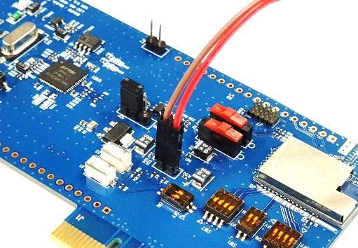
UM-WI-037
DA16200 Quick Start Guide

Contents
Abstract ................................................................................................................................................ 1
Contents ............................................................................................................................................... 2
1    Terms and Definitions ................................................................................................................... 4
2    References ..................................................................................................................................... 4
3    Introduction.................................................................................................................................... 5
4    Register and Download SDK ........................................................................................................ 5
5    Evaluation Kit ................................................................................................................................ 6
     5.1 Basic EVK ............................................................................................................................. 6
          5.1.1      DA16200 Module EVK ........................................................................................... 6
          5.1.2      Wi-Fi Mode Setup .................................................................................................. 8
          5.1.3      Connect the DA16200 Board ................................................................................. 8
          5.1.4      Configure the Serial Port for UART ..................................................................... 10
          5.1.5      Setup for Station Mode ........................................................................................ 11
     5.2 Snippet EVK ........................................................................................................................ 13
     5.3 How to Control EVK ............................................................................................................ 13
6    Structure of SDK ......................................................................................................................... 14
     6.1 SDK ..................................................................................................................................... 14
     6.2 Images................................................................................................................................. 14
7    Build SDK and Download Image ................................................................................................ 15
     7.1 Build the SDK ...................................................................................................................... 15
     7.2 Download an Image ............................................................................................................ 15
8    Sample Project Testing ............................................................................................................... 16
     8.1 Test the Sample Project ...................................................................................................... 16
     8.2 Reference Test of UDP ....................................................................................................... 16
         8.2.1     Block Diagram ..................................................................................................... 17
         8.2.2     DA16200 Setup Procedure for the UDP Client ................................................... 17
         8.2.3     Peer PC (Hercules) Setup Procedure for the UDP Server .................................. 18
         8.2.4     Test Sequence ..................................................................................................... 20
     8.3 Reference Test of TCP ....................................................................................................... 21
         8.3.1     TCP Block Diagram ............................................................................................. 21
     8.4 Reference Test of MQTT .................................................................................................... 24
Appendix A Application Features .................................................................................................... 25
   A.1 config_generic_sdk.h .......................................................................................................... 25
   A.2 sys_common_feature.h ....................................................................................................... 26
Revision History ................................................................................................................................ 27

User Manual                                                      Revision 1.2                                                        25-Mar-2020

CFR0012                                                                2 of 28                                          © 2021 Dialog Semiconductor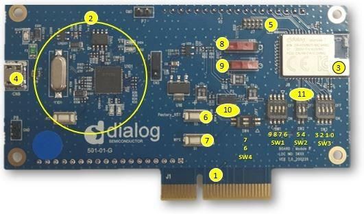
UM-WI-037
DA16200 Quick Start Guide

FiguresFigure 1: Dialog's Wi-Fi Materials for Registered Users ........................................................... 5
Figure 2: Dialog's Wi-Fi Materials for Unregistered Users .................................................................... 6
Figure 3: DA16200 EVK Hardware Configuration ................................................................................. 7
Figure 4: JTAG Pin Connection ............................................................................................................. 7
Figure 5: Test Point for Current Measurement ...................................................................................... 8
Figure 6: Check COM Ports on Device Manager .................................................................................. 9
Figure 7: Serial Port Setup .................................................................................................................. 10
Figure 8: Easy Setup Start .................................................................................................................. 11
Figure 9: Country Selection ................................................................................................................. 11
Figure 10: Station Mode Selection ...................................................................................................... 11
Figure 11: AP Selection ....................................................................................................................... 12
Figure 12: Check Wi-Fi Configuration ................................................................................................. 13
Figure 13: Wi-Fi Configuration Completed .......................................................................................... 13
Figure 14: SDK Folder Structure ......................................................................................................... 14
Figure 15: SDK Images ....................................................................................................................... 14
Figure 16: Build the SDK ..................................................................................................................... 15
Figure 17: Download an Image ........................................................................................................... 15
Figure 18: Sample Project Folder Structure ........................................................................................ 16
Figure 19: UDP Block Diagram ........................................................................................................... 17
Figure 20: Setup DA16200 for the UDP Client .................................................................................... 18
Figure 21: Setup Peer PC for the UDP Client ..................................................................................... 19
Figure 22: The UDP Client .................................................................................................................. 20
Figure 23: The UDP Server ................................................................................................................. 20
Figure 24: TCP Block Diagram ............................................................................................................ 21
Figure 25: Setup DA16200 for the TCP Client .................................................................................... 22
Figure 26: Setup Peer PC for the TCP Client...................................................................................... 23
Figure 27: TCP Server ......................................................................................................................... 24
Figure 28: TCP Client .......................................................................................................................... 24
TablesTable 1: GPIO, SPI Selective Switches ...................................................................................... 8
Table 2: SDK Images .......................................................................................................................... 14
Table 3: Features in config_generic_sdk.h ......................................................................................... 25
Table 4: Features in sys_common_feature.h ...................................................................................... 26

User Manual                                                   Revision 1.2                                                    25-Mar-2020

CFR0012                                                             3 of 28                                       © 2021 Dialog Semiconductor
UM-WI-037
DA16200 Quick Start Guide

1       Terms and Definitions
DPM                Dynamic Power Management
UART               Universal Asynchronous Receiver-Transmitter
RTC                Real Time Clock
WPS                Wi-Fi Protected Setup
SDK                Software Development Kit
CLI                Command Line Interface
EVK                Evaluation Kit
IAR                Abbreviation of Ingenjörsfirman Anders Rundgren (Anders Rundgren
                   Engineering Company)
RF                 Radio Frequency
UDP                User Datagram Protocol

2       References
[1]    UM-WI-023, DA16200_EVK_User_Manual, User Manual, Dialog Semiconductor
[2]    UM-WI-012, DA16200_SPI_SFlash_Downloader, User Manual Rev 1v5, Dialog Semiconductor
[3]    UM-WI-002, DA16200_SDK_Programmer_Guide, User Manual Rev 1v5, Dialog Semiconductor
[4]    UM-WI-007, DA16200_Example_Application_Manual, User Manual Dialog Semiconductor
[5]    UM-WI-010, DA16200_MQTT_Programmer_User_Manual, User Manual, Dialog Semiconductor
[6]    UM-WI-005, DA16200_DPM_Manager_User_Manual, User Manual, Dialog Semiconductor
[7]    AN-WI-002_DA16200_BT_Coexist_Application_Note, Application Note, Dialog Semiconductor
[8]    UM-WI-028, DA16200_SoftAP_User_Provisioning, User Manual, Dialog Semiconductor
[9]    UM-WI-029, DA16200_WiFi_Connection_Notification, User Manual, Dialog Semiconductor
[10]   DA16200_OTA_Update_MCU_Firmware_Dev., Dialog Semiconductor
[11]   UM-WI-036, DA16200_OTA_Update, User Manual, Dialog Semiconductor

User Manual                              Revision 1.2                              25-Mar-2020

CFR0012                                     4 of 28                      © 2021 Dialog Semiconductor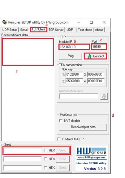
UM-WI-037
DA16200 Quick Start Guide
3 Introduction
The DA16200 is a highly integrated ultra-low power Wi-Fi system on a chip (SoC) and allows users
to develop a Wi-Fi solution on a single chip. The user implements their application with the DA16200
SDK, and the compile environment is the IAR. This document describes how to set up the
development environment for the DA16200 EVB and SDK.
4 Register and Download SDK
The official latest SDK is available on Dialog support site: https://support.dialog-semiconductor.com.
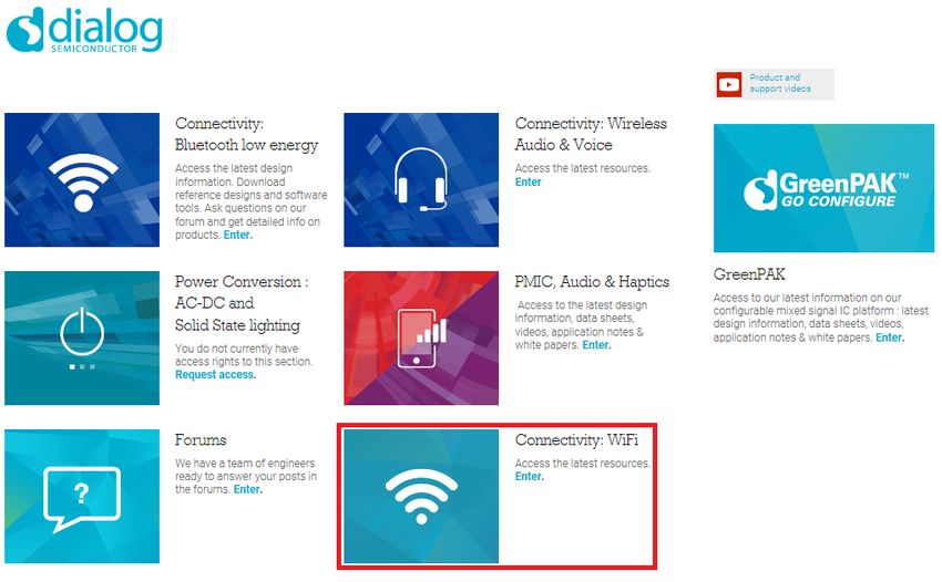
To access the site you must first register, and then you can access all Dialog Wi-Fi materials as in
Figure 1.
Figure 1: Dialog's Wi-Fi Materials for Registered Users
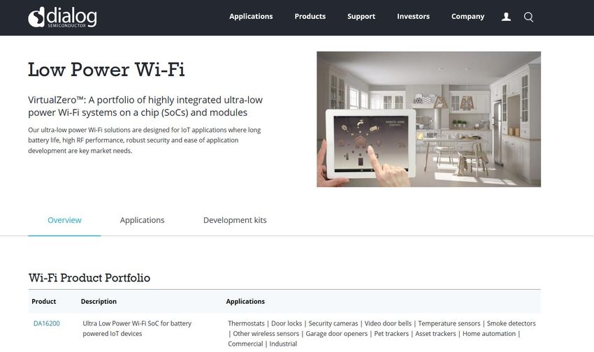
You can also download some materials without registration using this link: https://www.dialog-
semiconductor.com/products/wi-fi.
User Manual Revision 1.2 25-Mar-2020
CFR0012 5 of 28 © 2021 Dialog Semiconductor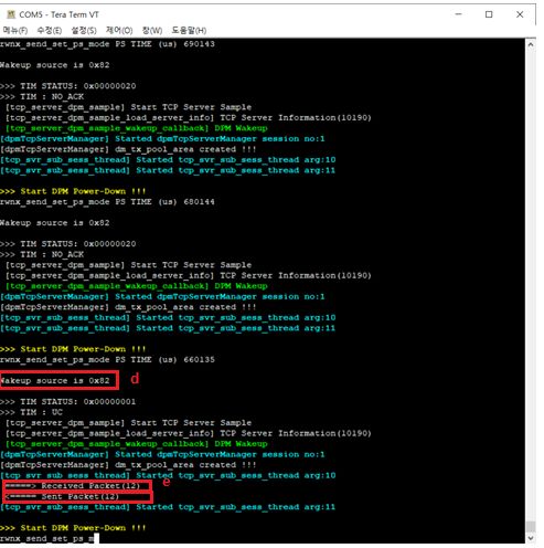
UM-WI-037
DA16200 Quick Start Guide

                    Figure 2: Dialog's Wi-Fi Materials for Unregistered Users

5       Evaluation Kit
If you did not prepare product for DA16200, you can use Dialog’s EVK for testing or development.

5.1       Basic EVK
You can test all Wi-Fi applications with Dialog's basic EVK and generic SDK. See [1].

5.1.1      DA16200 Module EVK
Figure 3 shows the hardware configuration of the DA16200 Module EVK.

User Manual                               Revision 1.2                                  25-Mar-2020

CFR0012                                       6 of 28                         © 2021 Dialog Semiconductor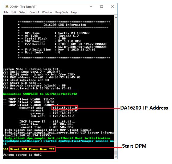
UM-WI-037
DA16200 Quick Start Guide

                           Figure 3: DA16200 EVK Hardware Configuration

DA16200 has the following components:
1. Main board: DA16200 module (DA16200MOD-AAC4WA32) is installed on the PCI type main
   board.
2. USB Interface part.
3. DA16200MOD-AAC4WA32 Wi-Fi Module.
4. USB Port: UART0 (for debug) and UART1 (for AT command).
5. JTAG PIN: to be able to connect I-jet (a JTAG debugger from IAR). See Figure 4.
   a. Pin 7 on each end is keyed with a white plug, so Pin 7 should be removed on EVK.

                                    Figure 4: JTAG Pin Connection

6. Factory Reset button: press for more than 5 seconds to initialize nvram data.
7.    WPS button: press to start WPS mode.
8.    RTC Wake-Up key: switch to wake up the board from the Sleep mode.
9.    RTC Power key: switch to turn the board on/off.
10.   Pin (P2): selected part in red color is for current measurement. For normal operation, this pin
      should be shorted. See Figure 5.
      a. Pull out the Short Pin cap and use the jumper wire to connect to measuring equipment.

User Manual                                  Revision 1.2                                   25-Mar-2020

CFR0012                                           7 of 28                         © 2021 Dialog Semiconductor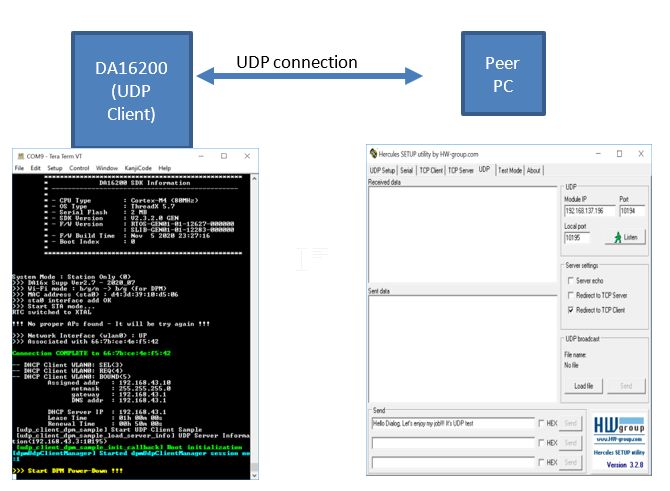
UM-WI-037
DA16200 Quick Start Guide

                           Figure 5: Test Point for Current Measurement

11. GPIO, SPI selective switches: SW2, SW3, SW4 (Default: on), SW1 (Default: off). See Table 1.
    For more details on how to use the pins, see the schematic of the 6.0 EVK in [2].

Table 1: GPIO, SPI Selective Switches
 Selective Switch            On                                      Off
 SW3: GPIO 0, 1, 2, 3        Image download using SPI 1.             Not defined.
 SW2: GPIO 4, 5              UART 1(TXD, RXD) to FT232H.             UART 1 to external MCU for Test.
 SW1: GPIO 6, 7              Image download using SPI 2.             WPS, Factory Reset.
 SW1: GPIO 8, 9              Image download using SPI 2.             Not defined.
 SW4: GPIO 6, 7              WPS, Factory Reset.                     Not defined.

5.1.2     Wi-Fi Mode Setup
This section describes how to set up the Station and the Soft-AP modes that are supported by
DA16200:
● Station: a mode that runs the 802.11 STA interface
● Soft-AP: a mode that runs the Software Access Point. Note that the Soft-AP mode does not
   support full-fledged commercial level Access Point features and is normally used for Provisioning

5.1.3     Connect the DA16200 Board
This section describes the installation procedure for the drivers, the configuration of the serial port,
and all necessary steps to verify the connection with the PC as well as solutions to any problems that
may occur.
On the first connection to a host PC with Microsoft Windows as operating system, the system detects
several devices and automatically installs all necessary drivers. If automatic installation does not
happen, then download and install the drivers from the following URL:
http://www.ftdichip.com/Drivers/CDM/CDM21224_Setup.zip.
There are two virtual COM ports created by the Windows driver:
● The first COM port (lower number, COM35 in this example) provides a UART interface for
   debugging or firmware download between the PC and the DA161200
● The second (higher number, COM36 in this example) is used for ATCOMMAND. See Figure 6.

User Manual                                 Revision 1.2                                      25-Mar-2020

CFR0012                                         8 of 28                             © 2021 Dialog Semiconductor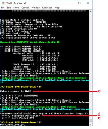
UM-WI-037
DA16200 Quick Start Guide

                  Figure 6: Check COM Ports on Device Manager

User Manual                     Revision 1.2                              25-Mar-2020

CFR0012                             9 of 28                     © 2021 Dialog Semiconductor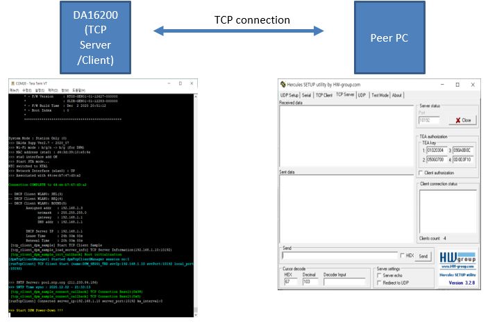
UM-WI-037
DA16200 Quick Start Guide

5.1.4     Configure the Serial Port for UART
On a Windows host, the Tera Term utility is used to fully validate the connection to the DA16200
EVK. Tera Term is a free software terminal emulator (communication program) that supports multiple
communication including serial port connections. You can download Tera Term from
https://ttssh2.osdn.jp. Run the teraterm-x.yy.exe executable and follow the installation wizard.
To ensure the communication between the DA16200 EVK and the host PC is properly established,
verify the UART connection between the two nodes:
1. Connect the DA16200 EVK to the PC with USB cable to USB Port.
2. Check if the host detects two serial ports as shown in Figure 6. The second is connected to
   UART (see Section 5.1).
3. Open Tera Term from the Windows Start menu.
4. In the Tera Term: New Connection dialog box:
   a. Select Serial.
   b. Select the COM Port to use.
   c. Click OK.
5. Select Setup > Serial Port and configure your UART port with the parameters as shown in
   Figure 7.
6. Open the Lowest COM port number assigned to the DA16200 EVK (see Figure 4) to figure out
   which port number is used by Windows by running the Device Manager. Make sure that the
   UART is configured as shown in Figure 7.

                                   Figure 7: Serial Port Setup

User Manual                              Revision 1.2                                 25-Mar-2020

CFR0012                                     10 of 28                        © 2021 Dialog Semiconductor
UM-WI-037
DA16200 Quick Start Guide
5.1.5 Setup for Station Mode
Use Easy Setup (a Wi-Fi configuration wizard) to easily configure the Wi-Fi functions for DA16200:
1. Run the setup command.
NOTE
From here on, the setup query statements will continue. So please answer the questions as in the following
steps.
2. Stop all services for the setting. Are you sure? [Yes/No]: type Yes.
See Figure 8.
Figure 8: Easy Setup Start
3. COUNTRY CODE? [Quit] (Default KR): type US for testing.
See Figure 9.
Figure 9: Country Selection
4. MODE? [1/2/Quit] (Default Station): type 1.
See Figure 10.
Figure 10: Station Mode Selection
User Manual Revision 1.2 25-Mar-2020
CFR0012 11 of 28 © 2021 Dialog SemiconductorUM-WI-037
DA16200 Quick Start Guide
5. SELECT SSID? (1~30/Manual/Quit): type 1.
See Figure 11.
a. Select the SSID of the AP to which you want to connect. If there is no AP that you want to
connect to, press Enter to rescan.
For example: SSID ACST_AC_TEST2 is selected for testing.
Figure 11: AP Selection
6. PSK-KEY (ASCII characters 8~63 or hexadecimal characters 64)? [Quit]
: ******** type the password that matches the encryption method of the selected AP.
7. WIFI CONFIGURATION CONFIRM? [Yes/No/Quit]: type Y. See Figure 12.
8. IP Connection Type? [Automatic IP/Static IP/Quit]: type A.
IP is automatically assigned by DHCP.
9. IP CONFIGURATION CONFIRM? [Yes/No/Quit]: type Y.
10. SNTP Client enables type N.
If time synchronization is not needed, then there is no need to run the SNTP Client.
User Manual Revision 1.2 25-Mar-2020
CFR0012 12 of 28 © 2021 Dialog SemiconductorUM-WI-037
DA16200 Quick Start Guide
11. Dynamic Power Management? [Yes/No/Quit]: type N.
See [1] for more information about DPM.
Figure 12: Check Wi-Fi Configuration
Once all settings are made as shown in Figure 12, the configuration is saved and the system will
reboot as shown in Figure 13.
Figure 13: Wi-Fi Configuration Completed
5.2 Snippet EVK
You can test the power consumption using Dialog's EVK. See [1].
5.3 How to Control EVK
You can test EVK with CLI. See [1].
User Manual Revision 1.2 25-Mar-2020
CFR0012 13 of 28 © 2021 Dialog SemiconductorUM-WI-037
DA16200 Quick Start Guide
6 Structure of SDK
The SDK folder structure is shown in Figure 14.
Figure 14: SDK Folder Structure
6.1 SDK
The DA16200 SDK is provided to use commonly. See [3].
6.2 Images
Various images are provided for various applications and each type of chipset.
Figure 15: SDK Images
You can use these images for testing or production without build through IAR.
Table 2: SDK Images
Image Description
_QFN_(ATCMD/WPA3)_vx.x.x.x You can test the QFN chipset using this image and run chipset through
ATCMD and WAP3 using any of these images.
_Manufacture_QFN_vx.x.x.x You can use this image to RF test for production.
User Manual Revision 1.2 25-Mar-2020
CFR0012 14 of 28 © 2021 Dialog SemiconductorUM-WI-037
DA16200 Quick Start Guide
7 Build SDK and Download Image
7.1 Build the SDK
To build the SDK:
1. Run the IAR project file: \customer\project\DA16xxx.eww.
2. Select the whole module, and then run Rebuild-all or Make.
NOTE
You should use IAR 7.30.4.xxxx. The other versions are not supported for DA16200. See [3].
Figure 16: Build the SDK
7.2 Download an Image
You can download an image with .ttl file in Tera Term. The .ttl is located in the image package with
a name Download_xxxx.ttl. See [1].
Figure 17: Download an Image
User Manual Revision 1.2 25-Mar-2020
CFR0012 15 of 28 © 2021 Dialog SemiconductorUM-WI-037
DA16200 Quick Start Guide
NOTE
There is a boot index information in sflash address of 0x9000.
If you use macro it will be erased to make the region for boot index 0.
If you download image manually you must check the region you download is matched with the boot index.
8 Sample Project Testing
The sample project is located in folder \sample and has the folder structure as in Figure 18. See
doxygen and [4].
Figure 18: Sample Project Folder Structure
All DPM samples are almost the same as the normal samples but also have additional logic for the
DPM control.
Each sample exists in each project independently, so you can build and test independently with other
sample images that also exist independently.
8.1 Test the Sample Project
To test the sample project:
1. Run \build\DA16xxx.eww in a project.
2. Build and download image located in the \img folder of the project.
8.2 Reference Test of UDP
See doxygen and [4].
User Manual Revision 1.2 25-Mar-2020
CFR0012 16 of 28 © 2021 Dialog SemiconductorUM-WI-037
DA16200 Quick Start Guide
8.2.1 Block Diagram
Figure 19: UDP Block Diagram
This example is described based on the Hercules utility. You can download it from https://www.hw-
group.com/software/hercules-setup-utility.
8.2.2 DA16200 Setup Procedure for the UDP Client
The project file is located in DA16200_SDK\sample\Network\UDP_Client_DPM.
To set up DA16200 for the UDP Client:
1. Build DA16200_SDK \sample\Network\UDP_Client_DPM\build\DA16xxx.eww.
2. Download an image from DA16200_SDK\sample\Network\UDP_Client_DPM\img.
3. Set the Station mode for testing the DPM mode by the CLI command. Do not enable the DPM
mode during setup.
[/DA16200] #setup
4. Setup the UDP server information (Server IP and Server Port: the peer PC is the UDP server).
[/DA16200] # nvram.setenv UDPC_SERVER_IP 192.168.43.134
[/DA16200] # nvram.setenv UDPC_SERVER_PORT 10195
[/DA16200] # dpm on
After DPM is on, DA16200 restarts automatically.
User Manual Revision 1.2 25-Mar-2020
CFR0012 17 of 28 © 2021 Dialog SemiconductorUM-WI-037
DA16200 Quick Start Guide
Figure 20: Setup DA16200 for the UDP Client
8.2.3 Peer PC (Hercules) Setup Procedure for the UDP Server
To set up peer PC for the UDP Server:
1. Run Hercules.
2. Select UDP (a).
3. Set the Client IP address and the UDP Port (DA16200 is the UDP Client) (b).
4. Set the UDP Server port (c).
5. Open the UDP connection (d).
User Manual Revision 1.2 25-Mar-2020
CFR0012 18 of 28 © 2021 Dialog SemiconductorUM-WI-037
DA16200 Quick Start Guide
6. Send the data (e).
○ The sent data is displayed on the (f).
○ The received data is displayed on the (g).
Figure 21: Setup Peer PC for the UDP Client
User Manual Revision 1.2 25-Mar-2020
CFR0012 19 of 28 © 2021 Dialog SemiconductorUM-WI-037
DA16200 Quick Start Guide
8.2.4 Test Sequence
The test sequence for UDP includes the following:
1. UDP Serve sends the data (a).
2. UDP Server displays the sent data (b).
3. UDP Client wakes up by RTC timer(c).
4. UDP Client receives the data (d).
5. UDP Client sends the received data (e).
6. UDP Server receives the data (f).
Figure 22: The UDP Client Figure 23: The UDP Server
User Manual Revision 1.2 25-Mar-2020
CFR0012 20 of 28 © 2021 Dialog SemiconductorUM-WI-037
DA16200 Quick Start Guide
8.3 Reference Test of TCP
See doxygen and [4].
8.3.1 TCP Block Diagram
Figure 24: TCP Block Diagram
User Manual Revision 1.2 25-Mar-2020
CFR0012 21 of 28 © 2021 Dialog SemiconductorUM-WI-037
DA16200 Quick Start Guide
8.3.1.1 DA16200 Setup Procedure for the TCP Client
The project file is located in DA16200_SDK\sample\Network\TCP_Client_DPM.
To set up DA16200 for the TCP Client:
1. Build DA16200_SDK \sample\Network\TCP_Client_DPM\build\DA16xxx.eww.
2. Download an image from DA16200_SDK\sample\Network\TCP_Client_DPM\img.
3. Set the Station mode for testing the DPM mode by CLI command. Do not enable the DPM mode
during setup.
[/DA16200] #setup
4. Set up the TCP Server information (Server IP and Server Port: peer PC is the TCP Server).
[/DA16200] # nvram.setenv TCPC_SERVER_IP 192.168.1.2
[/DA16200] # nvram.setenv TCPC_SERVER_PORT 10192
[/DA16200] # dpm on
After DPM is on, DA16200 restarts automatically.
Figure 25: Setup DA16200 for the TCP Client
User Manual Revision 1.2 25-Mar-2020
CFR0012 22 of 28 © 2021 Dialog SemiconductorUM-WI-037
DA16200 Quick Start Guide
8.3.1.2 Peer PC (Hercules) Setup Procedure for the TCP Client
To set up the peer PC (Hercules) for the TCP Client:
1. Run Hercules.
2. Select the TCP Client (a).
3. Set the TCP Server IP Address and Port to connect (b and c).
4. Test the TCP connection (d).
5. Send the data (e).
6. The connection information, the sent data and received data are displayed on the (f).
Figure 26: Setup Peer PC for the TCP Client
8.3.1.3 Test Sequence
The test sequence for TCP includes the following:
1. Restart DA16200, and then click the Connect button.
2. TCP Client shows the TCP Connection information (a).
3. TCP Client sends the data (b).
4. TCP server displays the sent data (in pink color) (c).
User Manual Revision 1.2 25-Mar-2020
CFR0012 23 of 28 © 2021 Dialog SemiconductorUM-WI-037
DA16200 Quick Start Guide
5. TCP Client wakes up by RTC timer (d).
6. TCP Client receives the data (e).
7. TCP Client sends the received data (f).
8. TCP Server receives the data (in black color) (g).
Figure 27: TCP Server Figure 28: TCP Client
8.4 Reference Test of MQTT
See [5].
User Manual Revision 1.2 25-Mar-2020
CFR0012 24 of 28 © 2021 Dialog SemiconductorUM-WI-037
DA16200 Quick Start Guide
Appendix A Application Features
You can enable or disable features in config_generic_sdk.h to fit your application.
There are two header files for the configuration:
● config_generic_sdk.h – for user configuration
● sys_common_feature.h – for common system function
However, you need an approval from Dialog to change the common system function.
A.1 config_generic_sdk.h
Table 3: Features in config_generic_sdk.h
Feature Description
__SUPPORT_WPS_BTN__ To support WPS that works with GPIO6.
__SUPPORT_FACTORY_RESET_BTN__ To support the Factory Reset button that is mapped to
GPIO7.
If it is detected, the factory reset function executes.
__SUPPORT_DPM_MANAGER__ You can use the DPM function with this feature.
If you set some functions for the DPM manager, then the
DPM process runs automatically.
See [6].
__SUPPORT_CONSOLE_PWD__ Enable to protect the log display or command through the
UART0 console.
You can access the console with a password (default
password is da16200 for DA16200).
__SUPPORT_BTCOEX__ Enable to control the RF switching between Wi-Fi and
Bluetooth. It is implemented with 3wire logic.
See [7].
__SUPPORT_UART1__ To communicate with Host (MCU) through UART, please
enable this.
For more information on the UART1 sample in SDK, see
\sample\Peripheral\UART1.
__SUPPORT_UART2__ To communicate with Host (MCU) through UART2, please
enable this.
__SUPPORT_SNTP_CLIENT__ To use the SNTP client, first enable it.
__SUPPORT_OTA__ DA16200 supports OTA to update the DA16200 images.
For more information on OTA sample in SDK, see
\sample\Network\OTA_Update. See [8].
__SUPPORT_HTTP_SERVER__ Enable to use the HTTP server.
See the HTTP sample in SDK:
\sample\Network\HTTP_Server.
__SUPPORT_HTTP_CLIENT__ Enable to use the HTTP client.
See the HTTP sample in SDK: \sample\Network\
HTTP_Client(DPM).
__SUPPORT_PROVISION__ SDK provides a sample of provisioning.
__SUPPORT_USER_PROVISION__ See [8].
__SUPPORT_MQTT__ Enable to use MQTT to connect with server.
User Manual Revision 1.2 25-Mar-2020
CFR0012 25 of 28 © 2021 Dialog SemiconductorUM-WI-037
DA16200 Quick Start Guide
Feature Description
__SUPPORT_ATCMD__ Da16200 supports AT command.
__ATCMD_IF_UART1__ You can use this command over various interface.
__ATCMD_IF_UART2__
__USER_UART_CONFIG__
__ATCMD_IF_SPI__
__ATCMD_IF_SDIO__
__SUPPORT_WIFI_CONN_CB__ To use the callback with the status when Wi-Fi is
connected or disconnected.
See [9].
__SET_WAKEUP_HW_RESOURCE__ To use RTC_WAKE_UP pin as interrupt while DA16200 is
awake. (DA16200 can be woken up from sleep by
triggering GPIO signal from external MCU although it is not
enabled.)
A.2 sys_common_feature.h
Some features may not affect the built firmware. Because some of them are included as library.
Table 4: Features in sys_common_feature.h
Feature Description
__ENABLE_UART1_CLOCK__ Enable to use a clock.
__ENABLE_GPIO_CLOCK__ Enable to use a clock.
__SUPPORT_MULTI_IP_IF__ DA16200 supports multiple IPs.
__SUPPORT_WPA3__ To use WPA3.
__SUPPORT_IEEE80211W ● To use PMF
__SUPPORT_WPA3_SAE__ ● To use SAE
__SUPPORT_WPA3_OWE__ ● To use OWE
To make the Wi-Fi connection faster when wakeup from
__SUPPORT_FAST_CONN_SLEEP_12__
sleep1 or 2.
To coordinate abnormal action when W i-Fi cannot be
__USER_DPM_ABNORM_WU_INTERVAL__ connected. You can modify the sleep duration and the
waken time.
To use Provisioning on secure.
__SUPPORT_PROVISION_TLS__
See [8].
DA16200 supports OTA to update the DA16200 images.
__OTA_HTTP_CLIENT__ See OTA sample in SDK: \sample\Network\OTA_Update.
See [8].
To use the HTTP client with the OTA function. You can use
__OTA_UPDATE_MCU_FW_
DA16200’s OTA process to upgrade MCU. See [10].
User Manual Revision 1.2 25-Mar-2020
CFR0012 26 of 28 © 2021 Dialog SemiconductorUM-WI-037
DA16200 Quick Start Guide
Revision History
Revision Date Description
1.2 25-Mar-2021 Modified description for DA16200 V2.3.4.0 SDK update.
Section 6.1
● Removed SDK Types.
● Table 2 Removed two SDK images.
Section 7.17.2 Added a note about boot index.
1.1 10-Feb-2021 Section 8.2.2 Updated location path.
Section 8.3.1.1 Updated location path.
Appendix A
● Table 3 Updated features.
● Table 4 Updated features.
18-Dec-2020 Initial version.
1.0
User Manual Revision 1.2 25-Mar-2020
CFR0012 27 of 28 © 2021 Dialog SemiconductorUM-WI-037
DA16200 Quick Start Guide
Status Definitions
Status Definition
The content of this document is under review and subject to formal approval, which may result in modifications or
DRAFT
additions.
APPROVED
The content of this document has been approved for publication.
or unmarked
Disclaimer
Unless otherwise agreed in writing, the Dialog Semiconductor products (and any associated software) referred to in this document are not
designed, authorized or warranted to be suitable for use in life support, life-critical or safety-critical systems or equipment, nor in applications
where failure or malfunction of a Dialog Semiconductor product (or associated software) can reasonably be expected to result in personal injury,
death or severe property or environmental damage. Dialog Semiconductor and its suppliers accept no liability for inclusion and/or use of Dialog
Semiconductor products (and any associated software) in such equipment or applications and therefore such inclusion and/or use is at the
customer’s own risk.
Information in this document is believed to be accurate and reliable. However, Dialog Semiconductor does not give any representations or
warranties, express or implied, as to the accuracy or completeness of such information. Dialog Semiconductor furthermore takes no
responsibility whatsoever for the content in this document if provided by any information source outside of Dialog Semiconductor.
Dialog Semiconductor reserves the right to change without notice the information published in this document, including, without limitation, the
specification and the design of the related semiconductor products, software and applications. Notwithstanding the foregoing, for any automotive
grade version of the device, Dialog Semiconductor reserves the right to change the information published in this document, including, without
limitation, the specification and the design of the related semiconductor products, software and applications, in accordance with its standard
automotive change notification process.
Applications, software, and semiconductor products described in this document are for illustrative purposes only. Dialog Semiconductor makes
no representation or warranty that such applications, software and semiconductor products will be suitable for the specified use without further
testing or modification. Unless otherwise agreed in writing, such testing or modification is the sole responsibility of the customer and Dialog
Semiconductor excludes all liability in this respect.
Nothing in this document may be construed as a license for customer to use the Dialog Semiconductor products, software and applications
referred to in this document. Such license must be separately sought by customer with Dialog Semiconductor.
All use of Dialog Semiconductor products, software and applications referred to in this document is subject to Dialog Semiconductor’s Standard
Terms and Conditions of Sale, available on the company website (www.dialog-semiconductor.com) unless otherwise stated.
Dialog, Dialog Semiconductor and the Dialog logo are trademarks of Dialog Semiconductor Plc or its subsidiaries. All other product or service
names and marks are the property of their respective owners.
© 2021 Dialog Semiconductor. All rights reserved.
RoHS Compliance
Dialog Semiconductor’s suppliers certify that its products are in compliance with the requirements of Directive 2011/65/EU of the European
Parliament on the restriction of the use of certain hazardous substances in electrical and electronic equipment. RoHS certificates from our
suppliers are available on request.
Contacting Dialog Semiconductor
United Kingdom (Headquarters) North America Hong Kong China (Shenzhen)
Dialog Semiconductor (UK) LTD Dialog Semiconductor Inc. Dialog Semiconductor Hong Kong Dialog Semiconductor China
Phone: +44 1793 757700 Phone: +1 408 845 8500 Phone: +852 2607 4271 Phone: +86 755 2981 3669
Germany Japan Korea China (Shanghai)
Dialog Semiconductor GmbH Dialog Semiconductor K. K. Dialog Semiconductor Korea Dialog Semiconductor China
Phone: +49 7021 805-0 Phone: +81 3 5769 5100 Phone: +82 2 3469 8200 Phone: +86 21 5424 9058
The Netherlands Taiwan
Dialog Semiconductor B.V. Dialog Semiconductor Taiwan
Phone: +31 73 640 8822 Phone: +886 281 786 222
Email: Web site:
enquiry@diasemi.com www.dialog-semiconductor.com
User Manual Revision 1.2 25-Mar-2020
CFR0012 28 of 28 © 2021 Dialog SemiconductorYou can also read