Hyper Installation/Operating Manual - Multi-functional Plug - KSB Web-Shop
←
→
Page content transcription
If your browser does not render page correctly, please read the page content below
Multi-functional Plug

Hyper

Installation/Operating Manual
Legal information/Copyright
Installation/Operating Manual Hyper

Original operating manual

All rights reserved. The contents provided herein must neither be distributed, copied, reproduced,
edited or processed for any other purpose, nor otherwise transmitted, published or made available to a
third party without the manufacturer's express written consent.
Subject to technical modification without prior notice.

© KSB SE & Co. KGaA, Frankenthal 27/01/2020

Contents

                                         Contents
1    General.................................................................................................................................................... 4
     1.1    Principles ...........................................................................................................................................................   4
     1.2    Target group.....................................................................................................................................................        4
     1.3    Other applicable documents............................................................................................................................                   4
     1.4    Symbols .............................................................................................................................................................    4
     1.5    Key to safety symbols/markings.......................................................................................................................                    4

2    Safety ...................................................................................................................................................... 6
     2.1    General..............................................................................................................................................................    6
     2.2    Intended use .....................................................................................................................................................       6
     2.3    Personnel qualification and personnel training .............................................................................................                             6
     2.4    Consequences and risks caused by non-compliance with this manual .........................................................                                               6
     2.5    Safety awareness ..............................................................................................................................................          7

3    Transport/Temporary Storage/Disposal............................................................................................... 8
     3.1    Checking the condition upon delivery ............................................................................................................                        8
     3.2    Transport...........................................................................................................................................................     8
     3.3    Storage ..............................................................................................................................................................   8
     3.4    Disposal .............................................................................................................................................................   9

4    Description............................................................................................................................................ 10
     4.1    General description ........................................................................................................................................         10
     4.2    Product information as per Regulation No. 1907/2006 (REACH).................................................................                                         10
     4.3    Designation.....................................................................................................................................................     10
     4.4    Name plate......................................................................................................................................................     10
     4.5    Design details..................................................................................................................................................     11
     4.6    Technical data.................................................................................................................................................      11
     4.7    Configuration and function...........................................................................................................................                12
     4.8    Scope of supply...............................................................................................................................................       12
     4.9    Accessories ......................................................................................................................................................   12

5    Installation at Site ................................................................................................................................ 13
     5.1    Safety regulations........................................................................................................................................... 13
     5.2    Checks to be carried out prior to installation............................................................................................... 13
     5.3    Electrical connection ...................................................................................................................................... 14

6    Commissioning/Start-up/Shutdown................................................................................................... 16
     6.1    Commissioning/Start-up ................................................................................................................................. 16
     6.2    Shutdown........................................................................................................................................................ 17
     6.3    Returning to service ....................................................................................................................................... 17

7    Servicing/Maintenance ........................................................................................................................ 18
     7.1    Maintenance ................................................................................................................................................... 18

8    Trouble-shooting.................................................................................................................................. 19
9    Related Documents .............................................................................................................................. 20
     9.1    Wiring diagram............................................................................................................................................... 20

10   EU Declaration of Conformity ............................................................................................................. 21
     Index ..................................................................................................................................................... 22

                                         Hyper                                                                                                                           3 of 24
1 General
1 General
1.1 Principles
This operating manual is valid for the type series and variants indicated on the front
cover.
The operating manual describes the proper and safe use of this equipment in all
phases of operation.
The name plate indicates the type series, the main operating data and the serial
number. The serial number uniquely describes the product and is used as
identification in all further business processes.
In the event of damage, immediately contact your nearest KSB service facility to
maintain the right to claim under warranty.
1.2 Target group
This operating manual is aimed at the target group of trained and qualified specialist
technical personnel.
1.3 Other applicable documents
Table 1: Overview of other applicable documents
Document Contents
Operating manual(s) for the Proper and safe use of the pump in all phases of
pump(s) operation
Wiring diagram Electrical connection
For accessories and/or integrated machinery components, observe the relevant
manufacturer's product literature.
1.4 Symbols
Table 2: Symbols used in this manual
Symbol Description
✓ Conditions which need to be fulfilled before proceeding with the
step-by-step instructions
⊳ Safety instructions
⇨ Result of an action
⇨ Cross-references
1. Step-by-step instructions
2.
Note
Recommendations and important information on how to handle
the product
1.5 Key to safety symbols/markings
Table 3: Definition of safety symbols/markings
2314.8/02-EN
Symbol Description
! DANGER DANGER
This signal word indicates a high-risk hazard which, if not avoided,
will result in death or serious injury.
! WARNING WARNING
This signal word indicates a medium-risk hazard which, if not
avoided, could result in death or serious injury.
4 of 24 Hyper1 General
Symbol Description
CAUTION CAUTION
This signal word indicates a hazard which, if not avoided, could
result in damage to the machine and its functions.
Explosion protection
This symbol identifies information about avoiding explosions in
potentially explosive atmospheres in accordance with EU Directive
2014/34/EU (ATEX).
General hazard
In conjunction with one of the signal words this symbol indicates a
hazard which will or could result in death or serious injury.
Electrical hazard
In conjunction with one of the signal words this symbol indicates a
hazard involving electrical voltage and identifies information about
protection against electrical voltage.
Machine damage
In conjunction with the signal word CAUTION this symbol indicates
a hazard for the machine and its functions.
2314.8/02-EN
Hyper 5 of 242 Safety
2 Safety
All the information contained in this section refers to hazardous situations.
! DANGER
In addition to the present general safety information the action-related safety
information given in the other sections must be observed.
2.1 General
▪ This operating manual contains general installation, operating and maintenance
instructions that must be observed to ensure safe operation of the system and
prevent personal injury and damage to property.
▪ Comply with all the safety instructions given in the individual sections of this
operating manual.
▪ The operating manual must be read and understood by the responsible specialist
personnel/operators prior to installation and commissioning.
▪ The contents of this operating manual must be available to the specialist
personnel at the site at all times.
▪ Information and markings attached directly to the product must always be
complied with and kept in a perfectly legible condition at all times. This applies
to, for example:
– Markings for connections
– Name plate
▪ The operator is responsible for ensuring compliance with all local regulations not
taken into account.
2.2 Intended use
The values specified in the technical product literature for the mains voltage, mains
frequency, ambient temperature and motor current must not be exceeded. The
control unit must only be operated in accordance with the instructions provided in
the operating manual and other applicable documents .
2.3 Personnel qualification and personnel training
All personnel involved must be fully qualified to install, operate, maintain and
inspect the equipment this manual refers to. The responsibilities, competence and
supervision of all personnel involved in installation, operation, maintenance and
inspection must be clearly defined by the operator.
Deficits in knowledge must be rectified by means of training and instruction
provided by sufficiently trained specialist personnel. If required, the operator can
commission the manufacturer/supplier to train the personnel.
Training on the control unit must always be supervised by specialist technical
personnel.
2.4 Consequences and risks caused by non-compliance with this manual
▪ Non-compliance with these operating instructions will lead to forfeiture of
warranty cover and of any and all rights to claims for damages.
▪ Non-compliance can, for example, have the following consequences:
– Hazards to persons due to electrical, thermal, mechanical and chemical
effects and explosions
2314.8/02-EN
– Failure of important product functions
– Failure of prescribed maintenance and servicing practices
– Hazard to the environment due to leakage of hazardous substances
6 of 24 Hyper2 Safety
2.5 Safety awareness
In addition to the safety information contained in this operating manual and the
intended use, the following safety regulations shall be complied with:
▪ Accident prevention, health regulations and safety regulations
▪ Explosion protection regulations
▪ Safety regulations for handling hazardous substances
▪ Applicable standards, directives and laws
2314.8/02-EN
Hyper 7 of 243 Transport/Temporary Storage/Disposal
3 Transport/Temporary Storage/Disposal
3.1 Checking the condition upon delivery
1. On transfer of goods, check each packaging unit for damage.
2. In the event of in-transit damage, assess the exact damage, document it and
notify KSB or the supplying dealer and the insurer about the damage in writing
immediately.
3.2 Transport
CAUTION
Improper transport
Damage to the device!
▷ Always transport the device properly and in its original packaging.
▷ For transport, observe the transport instructions on the original packaging.
▷ Do not throw device.
1. Upon receipt, unpack the control unit and check for in-transit damage.
2. Report any in-transit damage to the manufacturer immediately.
3. Dispose of packaging material in accordance with local regulations.
4. Make sure that the ambient conditions are met.
Switch off the control unit prior to transporting it.
Table 4: Ambient conditions for transport
Ambient condition Value
Relative humidity Max. 80% (no condensation)
Ambient temperature -10 °C to + 70 °C
3.3 Storage
CAUTION
Damage during storage due to humidity, dirt or vermin
Corrosion/contamination of the control unit!
▷ For outdoor storage cover the (packed or unpacked) control unit and
accessories with water-proof material.
If the ambient conditions for storage are met, the function of the control unit is
safeguarded even after a prolonged period of storage. If properly stored indoors, the
equipment is protected for a maximum of 12 months.
▪ Store the control unit in dry, vibration-free conditions and, if possible, in its
original packaging.
▪ Store the control unit in a dry room at constant atmospheric humidity.
▪ Prevent excessive fluctuations in atmospheric humidity.
Table 5: Ambient conditions for storage
2314.8/02-EN
Ambient condition Value
Relative humidity Max. 85 % (no condensation)
Ambient temperature -10 °C to + 70 °C
8 of 24 Hyper3 Transport/Temporary Storage/Disposal
3.4 Disposal
Electrical or electronic equipment marked with the adjacent symbol must not be
disposed of in household waste at the end of its service life.
Contact your local waste disposal partner for returns.
If the used electrical or electronic equipment contains personal data, the operator is
responsible for deleting it before the equipment is returned.
NOTE
Due to certain components it contains, the device is classified as special waste and
meets RoHs 2011/65/EC requirements.
Once decommissioned, the device must be properly disposed of in accordance with
local regulations.
2314.8/02-EN
Hyper 9 of 244 Description
4 Description
4.1 General description
▪ Motor protection plug for protecting a three-phase motor
▪ Control unit for level-dependent control of a three-phase motor
4.2 Product information as per Regulation No. 1907/2006 (REACH)
For information as per chemicals Regulation (EC) No. 1907/2006 (REACH), see http://
www.ksb.com/reach.
4.3 Designation
Example: Hyper 115.1
Table 6: Designation key
Code Description
Hyper Type series
115 Maximum current [A]
115 Maximum current × 10
Example: 11.5 A × 10 = 115
.1 Code number (type series generation)
4.4 Name plate
KSB SE & Co. KGaA
Johann-Klein-Straße 9
D-67227 Frankenthal
1 4
Typ: HYPER 26.1 2018w37
2
3
UE: 3/N/PE AC 400 V 50/60 Hz
IE: 1,8 - 2,6 A
01056098 Made in Germany ZNI 1448J
Fig. 1: Name plate (example)
1 Type series 3 Rated current
2 Rated voltage 4 Year / calender week of construction
2314.8/02-EN
10 of 24 Hyper4 Description
4.5 Design details
Design
▪ Control unit for level-dependent control of a three-phase motor
▪ Impact-resistant plastic housing
▪ DOL starting
Automatic functions
▪ Level measurement via float switch
▪ Phase inverter
▪ Motor monitoring up to 4 kW
▪ Manual-0-automatic selector switch
▪ Connection suitable for variable power cable diameters
▪ Bend protection for the power cable
▪ Strain relief for the power cable
▪ Reset function
▪ Contactor
▪ Motor protection by motor protection relay and thermal circuit breaker
Signalling functions and display functions
▪ Colour-coded LED display
Electrical connection
▪ CEE plug, 5-pole for 3/N/PE, 16 A / 6 h
▪ IP54 enclosure
4.6 Technical data
Table 7: Technical data
Characteristic Value
Nominal operating voltage to IEC 38 V [V AC] 3/N/PE, 400 V AC / 50 Hz
Maximum setting range I [A] ▪ 1,8
▪ 2,6
▪ 3,7
▪ 5,5
▪ 8,0
▪ 11,5
Nominal insulation voltage V [V AC] 690
Control voltage V [V AC] 230
Enclosure P [kW] IP 54
Mains type TN-C-S mains
Dimensions (L × W × H) [mm] 280 × 90 × 85
Weight [kg] 1,0
2314.8/02-EN
Hyper 11 of 244 Description
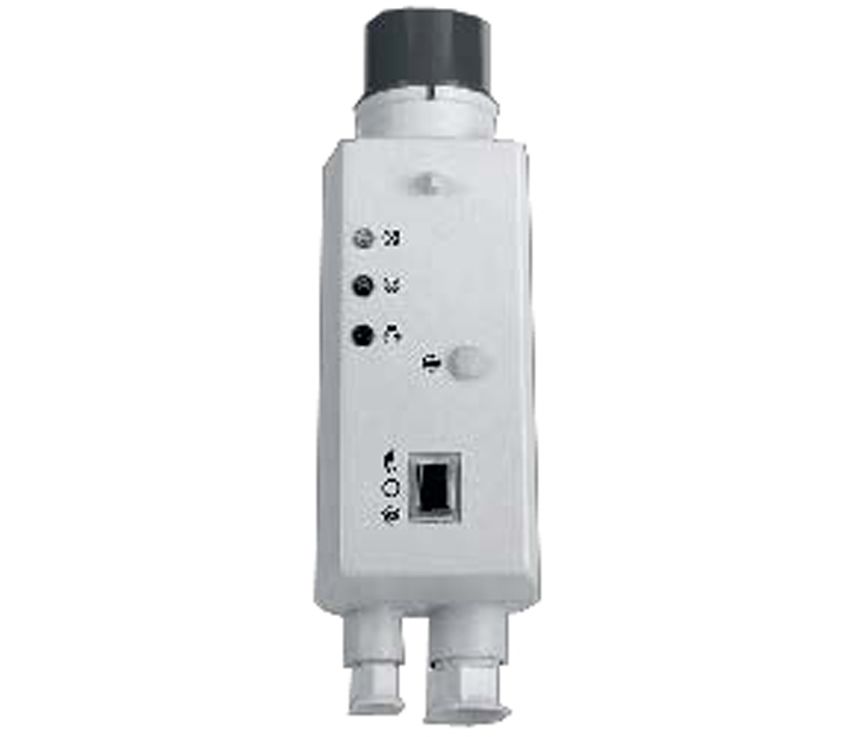
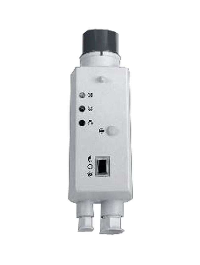
4.7 Configuration and function
1
8
7
2
6
5
4 3
Fig. 2: Description of the multi-functional plug
1 CEE plug 5 Manual-0-automatic selector switch
2 Reset button 6 Fault indication lamp
3 Pump connection 7 “In operation” lamp
4 Float switch connection 8 Direction of rotation indicator lamp
Design Compact control unit in a plug housing for the protection and level-dependent
control of pump sets up to 4 kW.
Function When the manual-0-automatic selector switch (5) is set to automatic, the pump is
started or stopped by the connected float switch in response to the fluid level. When
the fluid level reaches the start-up level, the pump is started up. When, after the
pumping-off process, the stop level is reached, the pump stops. By setting the
manual-0-automatic selector switch to manual the pump can be started manually for
short-time operation. When the manual-0-automatic selector switch is set to 0, the
entire system including pump is at a standstill. Both in manual mode and in
automatic mode the pump is continuously protected against thermal overload by the
integrated thermal circuit breaker. The control unit cover is designed with three
lamps. The fault indication lamp (6) signals a pump fault, which is triggered by a
bimetal switch or motor protection relay. The “in operation” lamp (7) indicates that
the pump is in operation (the contactor responds). The direction of rotation indicator
lamp (8) lights up when the rotary field of the power supply is incorrect (anti-
clockwise rotary field).
4.8 Scope of supply
The following items are included in the scope of supply:
▪ Impact-resistant plastic housing
▪ Power contactor
▪ Motor protection relay
▪ Colour-coded LED display
▪ Terminal strip for sensor connection
4.9 Accessories
2314.8/02-EN
▪ Float switch, circuit open in upper float position
▪ Float switch, circuit closed in upper float position
▪ Dry running protection
12 of 24 Hyper5 Installation at Site
5 Installation at Site
5.1 Safety regulations
DANGER
Incorrect installation
Danger to life!
▷ The control unit must be installed in a flood-proof location.
▷ Never install the control unit in potentially explosive atmospheres.
▷ Do not use the control unit for controlling pumps in potentially explosive
atmospheres.
▷ For integration in an external control system observe the directives for low-
voltage switchgear and controlgear assemblies.
5.2 Checks to be carried out prior to installation
The place of installation must meet the following requirements:
▪ Dry
▪ Frost-proof
▪ Well-ventilated
▪ Flood-proof
▪ Installation in potentially explosive atmospheres is not permitted.
Ambient conditions
The ambient conditions specified in the following table must be observed:
Table 8: Ambient conditions
Characteristic Value
Temperature during operation -10 °C to +50 °C
Relative humidity Non-condensing
Installation altitude 1000 m above MSL (max.)
2314.8/02-EN
Hyper 13 of 245 Installation at Site
5.3 Electrical connection
DANGER
Unintentional contact with live components
Danger of death from electric shock!
▷ Pull the control unit out of the CEE socket.
▷ Ensure that the mains connection cannot be re-energised unintentionally.
CAUTION
Improper electrical connection
Damage to the control unit / control cabinet!
▷ Check the type of current and voltage of the mains.
▷ For connecting pump power cables with flexible cores, attach wire end sleeves
to the core ends that are to be connected to the control unit.
▷ Observe the wiring diagrams. (ð Section 9.1, Page 20) .
CAUTION
Technical pump data not taken into account
Damage to the control unit!
▷ Connect only pumps with technical data (particularly rated current) that
matches this control unit.
NOTE
Connect the thermal circuit breaker with the corresponding cores of the pump
power cable. On pumps without a thermal circuit breaker a bridge must be inserted
into the control unit.
ü The mains voltage at the site has been verified against the data on the name
plate.
ü The wiring diagram is on hand.
1. Open the housing.
2. Guide the power cables through the corresponding cable glands.
3. Make sure that the sealing elements are properly positioned. Tighten the cable
glands (strain relief).
4. Connect the control unit in accordance with the wiring diagram.
(ð Section 9.1, Page 20)
5. Set the motor protection relay to the rated current.
6. Connect the power cable available on site so as to ensure a clockwise rotating
field.
2314.8/02-EN
14 of 24 Hyper5 Installation at Site
5.3.1 Setting the level-dependent control
CAUTION
Obstructed float switch
Flooding caused by pump not stopping!
Dry running caused by pump not stopping!
▷ The float switch must be fitted in such a way that it is able to move freely.
▷ The pump must be started up before the fluid handled reaches the upper edge
of the tank.
▷ The pump must be stopped before the fluid handled drops down to the suction
openings.
Setting the switching The pump is started and stopped by a float switch or level sensor. The float switch
points closes the circuit in upper float position.
▪ When the fluid handled reaches the start-up level or the float switch reaches an
upper angular position of 30°, the pump starts up.
▪ When the fluid handled reaches the stop level or the float switch reaches a lower
angular position of 30°, the pump stops.
▪ The switching points are indicated by a clearly audible switching noise in the
float housing.
▪ The switching points must be at least 40 cm apart.
Routing the float switch ü The switching level is set at the site.
cable 1. Determine the fastening height of the float switch cable at the discharge line,
handle or other suitable points.
2. Observe the required free cable length of the float switch.
3. The minimum free float switch cable length measured from the antikink bush is
10 cm.
4. Fasten the float switch cable with suitable fasteners.
2314.8/02-EN
Hyper 15 of 246 Commissioning/Start-up/Shutdown
6 Commissioning/Start-up/Shutdown
6.1 Commissioning/Start-up
6.1.1 Prerequisites for commissioning/start-up
Before commissioning/starting up the control unit, make sure the following
conditions are met:
▪ The VDE standards and regulations applicable in the country of use are complied
with.
▪ The power cable of the pump has been connected.
▪ The thermal circuit breaker has been connected.
▪ The power cable has been connected correctly (clockwise rotating field for three-
phase motors).
▪ The power cable of the float switch has been connected.
6.1.2 Start-up
CAUTION
Switching to manual mode with water level not reaching the start-up level
Damage to the pump!
▷ Only operate the pump in manual mode when the water level is above the
start-up level.
For commissioning/start-up set the switch to automatic.
Exception: When the switch is set to manual the pump can be started up directly.
Select manual mode for emergencies only (e.g. floods, fire-fighting water) or for
checking the direction of rotation.
Table 9: Description of the manual-0-automatic selector switch
Setting Function
Manual The motor is started up manually.
0 The motor is OFF.
Automatic The float switch starts and stops the motor.
ü The operating manual of the pump is on hand and is observed.
ü The float switch has been installed properly.
ü The housing is open.
1. Set the manual-0-automatic-selector switch to 0.
2. Check the setting of the motor protection relay against the rated current of the
motor; adjust the motor protection relay if required.
3. Re-set the motor protection relay by pressing the button.
4. Close the housing.
5. To establish the power supply plug the control unit into the CEE socket and set
the site-supplied safety device to ON.
6. If three-phase motors are used, check the direction of rotation.
2314.8/02-EN
ð To do so briefly set the manual-0-automatic selector switch to manual (only if
the water level is above the start-up level) and check the direction of
rotation indicator (LED).
7. Set the manual-0-automatic selector switch to automatic.
16 of 24 Hyper6 Commissioning/Start-up/Shutdown
6.2 Shutdown
DANGER
Unintentional contact with live parts
Danger of death from electric shock!
▷ De-energise the mains connection.
▷ Take steps to ensure that the mains connection cannot be re-energised
unintentionally.
1. Set the manual-0-automatic-selector switch to 0.
2. Pull the control unit out of the CEE socket.
3. Prior to any work on the control unit, use a voltmeter to verify that all phases
are dead.
6.3 Returning to service
For returning the equipment to service, observe the sections on commissioning/start-
up (ð Section 6.1, Page 16) .
2314.8/02-EN
Hyper 17 of 247 Servicing/Maintenance
7 Servicing/Maintenance
7.1 Maintenance
Check the proper functioning of the control unit once per year.
2314.8/02-EN
18 of 24 Hyper8 Trouble-shooting
8 Trouble-shooting
WARNING
Improper work to remedy faults
Risk of injury!
▷ For any work performed to remedy faults, observe the relevant information
given in this instruction manual and/or in the product literature provided by the
accessories manufacturer.
If problems occur that are not described in the following table, consultation with KSB
Service is required.
A Pump is running, but does not deliver
B Fault indication lamp is lit
C Pump has started, but stops above stop level
D Fault indication lamp is lit after pump start-up
E Pump does not stop.
Table 10: Trouble-shooting
A B C D E Possible cause Remedy
✘ - - - - Manual-0-automatic selector switch set to 0. Set manual-0-automatic switch to automatic.
✘ - - - - Amber lamp at motor protection relay is lit. Press the reset key of the motor protection relay.
✘ - - - - Thermal circuit breaker not connected or not Connect the thermal circuit breaker; if it is not
provided provided, connect supplied bridge to 1 and 2.
✘ - - - - Water level below start-up level Wait for inflow, then check again.
✘ - - - - Power cable of control unit does not supply Check power supply.
power.
- ✘ - - - Motor protection relay has tripped. Check pump.
- ✘ - - - Thermal circuit breaker not connected or not Connect the thermal circuit breaker.
provided If no thermal circuit breaker is provided, connect
supplied bridge to 1 and 2.
- ✘ ✘ - - Thermal circuit breaker has tripped. Pump will re-start after cooling down.
If the thermal circuit breaker trips repeatedly,
have the pump and motor mechanically and
electrically checked by KSB Service.
- - - ✘ - Incorrect setting of motor protection relay Set it to the rated current of the motor.
- - - ✘ - Thermal circuit breaker has tripped. Pump will re-start after cooling down.
If the thermal circuit breaker trips repeatedly,
have the pump and motor mechanically and
electrically checked by KSB Service.
- - - ✘ - Phase failure Check power cable.
- - - - ✘ Float switch is stuck. Release and check for free movement.
- - - - ✘ Incorrect pump selection Have it checked by KSB Service.
- - - - ✘ Manual-0-automatic selector switch is set to Set the manual-0-automatic selector switch to
manual. automatic.
2314.8/02-EN
Hyper 19 of 249 Related Documents
9 Related Documents
9.1 Wiring diagram
L1 L2 L3 N PE
L3
LED1 L2
L1
LED2
N
LED3 96
S
1 3 5 A1 A0H 1
K1 K1 S1
2 4 6 A2 1a 1b
1 3 5 96
F1 F1
2 4 6 95 X1 PE PE br bl 4 S
1 2 3 5 4
M1
U1 V1 W1 22 21 PE
M BN
3~ S2
BU
PE
Fig. 3: Wiring diagram of the multi-functional plug
LED1 Direction of rotation indicator (amber lamp)
LED2 “In operation” indicator (green lamp)
LED3 Fault indicator (red lamp)
K1 Contactor
F1 Motor protection relay
X1 Terminal strip
M1 Motor
S2 Float switch
S1 Manual-0-automatic selector switch
2314.8/02-EN
A Automatic
0 Zero
H Manual
20 of 24 Hyper10 EU Declaration of Conformity
10 EU Declaration of Conformity
Manufacturer: KSB SE & Co. KGaA
Johann-Klein-Straße 9
67227 Frankenthal (Germany)
The manufacturer herewith declares that the product:
type Hyper
Serial number range: 2020w01 to 2021w52
▪ is in conformity with the provisions of the following Directives as amended from time to time:
– 2014/30/EU: Electromagnetic Compatibility (EMC)
– 2014/35/EU: Electrical Equipment Designed for Use within Specific Voltage Limits (Low Voltage)
– 2011/65/EU: Restriction of the Use of Certain Hazardous Substances in Electrical and Electronic Equipment
(RoHS)
The manufacturer also declares that
▪ the following harmonised international standards have been applied:
– EN 60204-1
– EN 61000-6-2, EN 61000-6-3
The EU Declaration of Conformity was issued in/on:
Frankenthal, 1 January 2020
Jochen Schaab
Head of Product Development Pump Systems and Drives
KSB SE & Co. KGaA
Johann-Klein-Straße 9
67227 Frankenthal
Hyper 21 of 24Index
Index
A
Automatic functions 11
C
Commissioning/start-up 16
D
Design 11
Designation 10
Disposal 9
E
Event of damage 4
K
Key to safety symbols/markings 4
N
Name plate 10
O
Other applicable documents 4
S
Safety 6
Safety awareness 7
Scope of supply 12
Signalling and display functions 11
Storage 8
T
Transport 8
Trouble-shooting
Causes and remedies 19
W
Warnings 4
Warranty claims 4
2314.8/02-EN
22 of 24 Hyper2314.8/02-EN KSB SE & Co. KGaA Johann-Klein-Straße 9 • 67227 Frankenthal (Germany) Tel. +49 6233 86-0 www.ksb.com
You can also read