Control and acquisition software for the U of C Seismic Physical Modelling Facility
←
→
Page content transcription
If your browser does not render page correctly, please read the page content below
Control software for physical modelling facility

Control and acquisition software for the U of C Seismic Physical
Modelling Facility

Joe Wong, Kevin W. Hall, and Rolf Maier

                                      ABSTRACT
   The University of Calgary Seismic Physical Modelling System has undergone
significant upgrading. In particular, the positioning system now uses high-precision, high
repeatability linear electric motors. Motor control and digital data acquisition are now
done by two commercial circuit boards installed in a desktop computer running under the
Windows XP Professional operating system. We present an overview of the configuration
process needed to enable the eight linear motors that constitute the new positioning
system.
   The use of two separate computer boards (one for motion control and one for data
acquisition), coupled with multichannel transmitter and receiver capability, require
complex software that synchronizes motion with acquisition. The successful
amalgamation of C and C++ code from the separate SDKs (software development kits)
provided with the two boards to obtain a single master control program constitutes a
simple application of robotics. We have formulated design criteria for control and
acquisition software to make scale-model seismic surveying an automatic and efficient
procedure. Prototype code based on these criteria, and combining functions from the two
separate SDKs, has been developed and is being tested in the Visual Studio integrated
development environment.
                                   INTRODUCTION
   The U of C Seismic Physical Modelling Facility has been in existence since the mid-
1980s (Cheadle et al., 1985; Lawton et al., 1989). It used stepper motors for positioning,
and positioning repeatability was poor. Its control program was written in the QuickBasic
language and executed on a desktop computer running under MS-DOS. By the early
2000s, both the programming language and the operating system were obsolete. Thus,
both the hardware and the software components of the original modelling facility needed
significant overhauling. It was decided in 2005 to completely rebuild the facility.
   The four fundamental and essential functions required by the Seismic Physical
Modelling System are positioning, seismic energy generation, seismic energy detection,
and digital data acquisition. The new hardware that fulfils these functions is described in
detail by Wong et al. (this volume). Positioning is provided by linear electric motors
assembled in a two-gantry, eight-axis configuration. Seismic energy generation is
provided by an array of piezoelectric transducers driven by electronic high-voltage
switching circuits. Seismic energy detection is done by another array of piezoelectric
transducers connected to high-frequency amplifiers and filters. Data acquisition is done
with a 14-bit digitizing board that provides up to 25 megasamples per second.
   Motor control is done by an ACR-8020 board from Parker Motion Corporation, and
digital data acquisition is done by a CS-1450 board from CompuScope Limited. Both
boards are installed in a desktop computer running under the Windows XP Professional

                      CREWES Research Report — Volume 20 (2008)                               1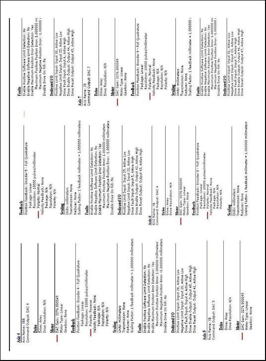
Wong, Hall, and Maier

operating system. Both boards are controlled by software commands issued through the
computer.
   Although the boards come with application software that operates them individually
and separately, an efficient operation requires that their functions must be controlled by a
single master program which must also select and activate transmitter and receiver
electronics. CREWES staff has undertaken to do this, using criteria based on experience
gained from using the old MS-DOS software. This report documents the development of
a prototype master program to control and synchronize the hardware using SDKs
(software development kits) provided with the hardware. This software enables us to
conduct seismic surveys with the Modeling Facility automatically and efficiently.
                  CONFIGURATION OF LINEAR MOTOR DRIVES
   The linear motors and associated components used in the positioning system are
described in the report by Wong et al. (2008) found elsewhere in this volume.
Connecting together the motor controller board ACR-8020, the breakout module, the
eight motor drives AR-04AE, the eight linear motors, and AC power (with switches and
fuses) properly is a fairly c complex task. Details on how to do this are given in the
documentation (*.pdf files downloaded from the Parker-Hannifin website www.
parkermotion.com) for the ACR-8020 board, the RBC module, and the AR-04AE motor
drives. Each motor drive has its own RS-232 channel that physically can be connected in
turn to the RS-232 communications channel in the computer. This is done using two
wires (red and green) on the cable and connector linking each motor drive and RBC
breakout module.
Initial Startup
   When a new AR-04AE motor drive is connected to the RBC breakout module and a
LXR-04 or LXR-06 linear motor, it must be enabled and configured before it can be
used. We do this with the application program Aries Support Tool, which comes on a CD
provided with the equipment. After this program is installed on the system computer and
executed, explanations on how to use it are found in documentation linked to by the
HELP button on the program menu.
Aries Support Tool
   The very first step in enabling a new motor and motor drive (after AC power is
applied to them) is to run Aries Support Tool. After the program indicates that
communications between the drive and the computer has been established, commands are
issued via the terminal emulator to enable the drive (details are found in the HELP
documentation for Support Tool). Initial configuration for the specific drive and motor is
done by choosing the GET CONFIGURATION FROM MOTOR option. All the
parameters required to control motion are loaded into the flash memory in the motor
drive and motor controller. The motor drive is enabled and successfully turned on when
the two LED indicator lights on the drive show one on with a steady green while the
other is off. Automatic tuning of the motor drive and motor now can be done by clicking
on the TUNING TOOL button. The operation initiated by this button is rather obscure,
but the computer responds by issuing a BEEP after several seconds, and then displays an
oscilloscope image showing two sine-like waves depicting commanded position and

2                       CREWES Research Report — Volume 20 (2008)
Control software for physical modelling facility
actual position. Note that the behavior of this TUNING TOOL does not correspond with
the description on this topic given by the HELP documentation.
After the TUNING TOOL operation is completed, we continue by clicking on the
SAVE CONFIGURATION TO FILE button. All the parameters generated by
configuration and tuning operations are saved to an ASCII file named, for example,
AXIS2.AST or YA.AST, where the extension .AST refers to Aries Support Tool, and the
name refers to the particular drive and motor. Subsequent configuration of a drive (new
or old) attached to this motor now can be done by choosing the LOAD CONFIGRATION
FROM FILE option.
Application program ACR-View
After using Support Tool to enable and turn on a motor drive for the very first time,
we have it convenient to use the application program ACR-View for further testing and
learning how to operate the eight drives and motors. The original version of ACR-View
was provided on a CD that came from Parker Motion Corporation with the equipment; an
updated version was downloaded from the website www.parkermotion.com. Unlike
Support Tool which uses and RS-232 connection to communication to each motor drive
one at a time, this program uses a bus cable to connect the ACR-8020 board to the RBC
board and all eight motor drives simultaneously.
Commands to control motor operation are issued in a language called AcroBasic.
Detailed documentation on ACR-View and AcroBasic is found in the PDF files ACR
User’s Guide 1 and 2, as well by clicking on the HELP button after ACR-View is
executed.
The documentation gives a very detailed description of the many parameters and bits
in the ACR-controller board and how they relate to the configuration, motion, and
position of the eight axes associated with the eight linear motors.
ACR-View must be used to re-configure all eight drives in a manner suitable to its
operation. ACR-View uses what it calls projects to set up operations for the eight axes
associated with the eight linear motors. Every time we name a new project, we must run
the configuration tool. An existing project can just be downloaded, but can be modified if
desired by running the configuration tool.
Project jw1
Using the Configuration Wizard within Acro-View, we have created a project called
jw1. This project is used for testing the motion control of the eight linear motors. As an
existing project jw1 can be downloaded every time the application ACR-View begins.
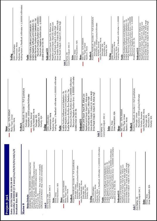
Figure 1 shows the contents of the file ACRWizardSummary.htl produced after
configuring the eight motor drives in this project. Note the items DAC GAIN and
POLARITY marked by red bars. The POLARITY VALUES have been given values so
the positive X motion is to the right, positive Y motion is away from the observer, and
positive Z motion is down. The DAC GAIN values are default values that cannot be set
within the configuration wizard, but can be changed by running programs such as
PROG0 (see below).
The default DAC GAIN values must be changed before any motion testing is
attempted. Motors assigned a normal POLARITY must have a negative DAC GAIN.
CREWES Research Report — Volume 20 (2008) 3Wong, Hall, and Maier
Motors assigned a reverse POLARITY must have a positive DAC GAIN. If the
POLARITY and the DAC GAIN sign are not matched in this way, the motor will run
away or move violently and uncontrollably.
The program PROG0 within the project jw1 sets the proper gain values. This program
also prepares the motor drives by assigning the motors (or axes) to proper MASTER and
SLAVE settings. It sets velocity, acceleration, and deceleration values (the numbers are
in units of mm/s and mm/s/s). The program may be viewed by bringing up the terminal
emulator within the project jw1. If the prompt PROG0 does not show up, type prog0 (the
commands in ACR-View are case insensitive) and ; type list , and
all the AcroBasic commands in PROG0 will be displayed (Appendix A).
On the right side of the terminal emulator screen are shown eight hot buttons preset
with specific commands such as XA ON, YA ON, ZA, AXES OFF, etc. The commands
on these buttons may be change by right clicking on the hot button panel.
Every time we want to run the motors, we can do the following:
Make sure the power switches for CONTROL and MOTOR are both off.
Manually position the carriages on the two gantries so they have room to move.
Start the application ACR-View and download the project jw1.
Connect with the bus.
Bring up the terminal emulator.
Type PROG0 and ; prog0> shows up on the terminal emulator;
Type list; the AcroBasic program shown on Figure 2 is displayed.
Type RUN and .
Bring up the PARAMETER STATUS panel:
• choose Encoder Position Parameter; this should show 0 or near 0 for axes 0 to
7;
• choose DAC Parameter, DAC Output; this should show 0 or near 0 for axes 0
to 7;
• choose DAC Parameter, DAC GAIN; the following numbers should be
displayed:
axis0 1638.4
axis1 -1628.4
axis2 -1638.4
axis3 -1638.4
axis0 1638.4
axis0 -1638.4
4 CREWES Research Report — Volume 20 (2008)Control software for physical modelling facility
axis0 1638.4
axis0 -1638.4 .
THE SIGNS OF THESE NUMBERS ARE VERY IMPORTANT; if they are wrong, the
motors will run away, or move violently and uncontrollably.
Click on the terminal emulator in Project jw1.
Turn on the AC power to CONTROL, and then the AC power to MOTOR in this
specific order.
Within the prog0 display, do the following.
Click on the XA ON button on the right-hand side of the terminal emulator.
Move the Gantry A carriage 10 mm to the right by typing XA10 .
Move the Gantry A carriage back to the origin position by typing XA0
.
Move the Gantry A carriage to position -10 mm by typing XA-10 .
Move the Gantry A carriage back to the origin position by typing XA/10
.
The origin position is the position that the carriage was at when the XA button was
clicked. A move to an absolute position happens if the number in the command is not
preceded by / (for example, XA -10 moves the carriage to a position 10 mm to the left of
the origin). A relative move happens when the number in the command is preceded by /
(e.g., AX /20 moves the carriage 20 mm to the right from its current position). The syntax
for all AcroBasic commands may be learned by reading the example programs and
documentation in the PDF files Programmer’s Guide, and the ACR User’s Guides 1 and
2.
Motion in the y and z directions for Gantry A can be tested by clicking on the YA ON
and ZA ON buttons, and then issuing commands like YA0, ZA /-10, etc.
Motion in the x, y, and z directions for Gantry B can be tested by clicking on the XB
ON, YB ON, and ZB ON buttons, and then issuing commands like XB/2, YA10, ZA /-
10, etc.
Note that absolute motion in the z direction must be negative, as the origin positions
for the ZA and ZB is always the lowest ends of the ZA and ZB axes, and up is defined as
the negative direction.
MOTION CONTROL AND DATA ACQUISITION SOFTWARE
The Programming Environment
The ACR-8020 board and the CS-1450 digital acquisition board both come with
software development kits (SDK) that use the C/C++ programming language within
MicroSoft’s Visual Studio Integrated Development Environment (IDE). Our goal is to
create a software module that synchronizes positioning, operation of the seismic
transmission and detection electronics, analogue-to-digital conversion, and data storage
CREWES Research Report — Volume 20 (2008) 5Wong, Hall, and Maier
in ASCII files and/or SEG-Y files. In order to facilitate development of programs that
meet our specific requirements, we modify and integrate existing C/C++ code from the
two separate SDKs.
Our software development begins by taking an existing Visual Studio project from the
CompuScope SDK. This project provides capability for doing digital data acquisition.
We chose average.prj as our starting point; this project has a C module (average.c) that
enables the user to sum up to 1024 repeated waveforms and saves the result in an ASCII
file. We added header and library files (acrolib.h, acrownt.lib, and acrownt.dll) from the
acrolib SDK to the project. We modified the file average.c by adding C++ initialization
code (copied from the file sendfile.cpp on the AcroLib SDK) and saved a copy with the
name mAverge.cpp . By adding C/C++ procedures that called the proper AcroLib
functions, we obtain a single program that combines the two functions required for a
master survey control program, motion control and seismic trace acquisition. Further
software development now involves modification of the mAverage.cpp code in order to
synchronize automatic motor motion and data acquisition.
BASIC MOTION CONTROL AND ACQUISITION
The two-gantry, eight-motor configuration of the positioning system is very flexible,
and it is possible to specify motion schedules that are quite complicated. However, at this
early stage in writing control and acquisition software, we concentrated on a program that
allows for fairly simple motion; future modifications will be made to include more
complex movements. We will describe a procedure for moving a single gantry on which
is mounted a linear array of transmitters and receivers with fixed Tx-Rx geometry. We
will then lay out a procedure for moving both gantries, one of which carries a transmitter
array and the other a receiver array. Included in both procedures is an acquisition loop
which acquires and saves traces from particular TX and RX combinations from the
arrays.
Flow charts and pseudocodes for single gantry motion and data acquisition
Systematic software design begins with a flow chart that identifies essential functions
and how they are linked in order to fulfill a desired goal. Generic pseudocode then is
written to represent the functions and links in the flow chart. Detailed real code in a
specific programming language is developed and tested using the software template
provided by the pseudocode.
Figure 2 is a flow chart showing the design for a move and acquire program aimed at a
single array of 8 transmitting transducers and two receiver transducers mounted on a
single gantry (Gantry A). This chart includes a box labeled Acquire Loop. The flow chart
for the Acquire Loop function is shown on Figure 3. Pseudocode for controlling single
gantry movement is found in Appendix B. Pseudocode for the acquisition loop is found
in Appendix C.
Pseudocode for Gantry A and Gantry B motion
Motion schedules for two gantries need to have checks for avoiding collisions between
gantries. Because of the way the two gantries are configured physically, collisions can
occur when the gantries move in the x-direction. For example, if Gantry A is at position
XA, and we want to move Gantry B from XB1 to XB2, we must make sure that XB1 and
6 CREWES Research Report — Volume 20 (2008)Control software for physical modelling facility
XB2 are both less than XA, or are both greater than XA. Similarly, if Gantry B is at
position XB, and we want to move Gantry A from XA1 to XA2, we must make sure that
XA1 and XA2 are both less than XB, or are both greater than XB.
Collisions can take place also with motion in y and z directions if the gantries are too
close together. To avoid this, there must always be some minimum clearance between the
two gantries. The coordinate system for the positioning system is defined so that, facing
the eight motor drives, Gantry A is to the left of Gantry B and the positive x-direction is
to the right. If the origins of the XA and XB axes are initialized at the same fixed point on
a model, then at any position XA and XB of the two gantries where there is a minimum
clearance (of , say, 10 mm), (XB-XA) >= 10.
Thus, collisions can be avoid if, at all time and for any value of XA and XB, we do no
moves unless (XB-XA) >= 10.
Appendix D lists an example of pseudocode for controlling two-gantry movement and
positioning
SEG-Y Files
Currently, the program mAverage.cpp saves each seismic trace from a particular Tx-
Rx pair location separately in single ASCII file. For high-resolution 3D seismic surveys,
a very large number of files will be written that will be difficult to use in any processing
software package. One of us (Maier) has written a C program running under LINUX that
reads the many ASCII files and re-writes the data into a SEG-Y with proper headers. In
the future, the SEG-Y file will be written inside the master control program.
Graphical User Interface
We want to have the Seismic Physical Modelling Facility in such a state so students
and staff not intimately involved with its construction and implementation can easily use
it to run trouble-free surveys. That means that the master control program must be
thoroughly tested and debugged. It also means that a good graphical user interface (GUI)
must be an integral component of the program.
Fortunately, once a programmer becomes knowledgeable in the Visual Studio IDE,
writing a GUI function is relatively straightforward. One of us (Hall) has taken steps to
produce such a GUI for our master control program to handle initialization of all motion
and acquisition parameters.
SUMMARY AND CONCLUSIONS
This report describes the procedures that must be taken to enable and do initial
configuration of each new Aries motor drive using the Aries Support Tool. Subsequent
configuration of all eight motor drives for coordinated motion, motion control testing,
and learning of the AcroBasic command language is most easily done using the
application program Acro-View provided by the manufactured of the components of the
linear positioning system. We described the Acro-View project jw1 and the program
PROG0 within jw1 that sets up Master and Slave assignments and sets proper DAC
GAIN values for all eight motors. Within the project jw1, we can issue AcroBasic
commands or write small test programs to learn the syntax of the AcroBasic language,
and to learn how various bits and parameters (of which there are very many) can be set,
cleared, and monitored in order to control the motion of the eight motors.
CREWES Research Report — Volume 20 (2008) 7Wong, Hall, and Maier
After learning how to use the AcroBasic language, the AcroBasic SDK and the
CompuScope SDK must be used together to develop a master control program that
synchronizes motion with data acquisition. Both SDKs use the C/C++ programming
language and the Visual Studio Integrated Development (IDE). Initial development of the
control software was facilitated by taking an existing sample project for the IDE
(average.prj, with the C code average.c) in the CompuScope SDK, combining the project
with .LIB and .DLL elements from the AcroLib SDK, and adding C++ code to produce a
new program mAverage.cpp. This program coordinates movement and positioning of
transmitting and receiver transducers with digital data acquisition of model seismograms.
Currently, mAverage.cpp is not optimized or fully debugged, but we can now use it to
collect model seismic data automatically
Other essential functions of a master control program for the Seismic Physical
Modelling System, a well-designed GUI and the archiving of seismic data in standard
SEG-Y format, are under development. The master control program is a complex piece of
software, and extensive testing and modification will continue into the future.
ACKNOWLEDGEMENTS
We are grateful to NSERC and the sponsors of the CREWES Project for supporting
the work described in this report.
REFERENCES
Cheadle, S.P., Bertram, M.B., and Lawton, D.C., 1985, A physical seismic modeling system, University of
Calgary: Current Research, Geological Survey of Canada, Paper, 85-1A, 149-153.
Lawton, D.C., Cheadle, S.P., Gallant, E.V., and Bertram, M.B., 1989, Elastic physical seismic modelling,
CREWES Research Report, 1, 273-288.
Sherlock, D.H., and Evans, B.J., 2001, The development of seismic reflection sandbox modeling, AAPG
Bulletin, 85, 1645-1659.
Wong, J., Hall, Kevin W., Bland, Henry C., Gallant, Eric V., and Bertram, Malcolm B., 2007, Some 2D
results from the U of C Seismic Physical Modelling Facility, CREWES Research Report, 19.
Wong, J., Hall, Kevin W., Gallant, Eric V., and Bertram, Malcolm B., 2008, Mechanical and electronic
design for the U of C Seismic Physical Modelling Facility, CREWES Research Report, 20.
8 CREWES Research Report — Volume 20 (2008)Control software for physical modelling facility FIG. 1(a). Contents of AcrWizardSummary.htl (Part I). CREWES Research Report — Volume 20 (2008) 9
Wong, Hall, and Maier

                                                                             .

                    FIG. 1(b). Contents of AcrWizardSummary.htl (Part II).

10                      CREWES Research Report — Volume 20 (2008)
Control software for physical modelling facility
FIG. 2. Flow chart for Gantry A motion.
CREWES Research Report — Volume 20 (2008) 11Wong, Hall, and Maier
FIG. 3. Flow chart for transducer selection and seismic trace acquisition.
APPENDIX A: LISTING OF PROG0 IN ACR-VIEW PROJECT jw1
' PROG0
ATTACH SLAVE2 AXIS2 "YA"
ATTACH AXIS2 ENC2 DAC2
DAC2 GAIN 1638.4
RES YA
'
ATTACH SLAVE3 AXIS3 "ZA"
ATTACH AXIS3 ENC3 DAC3
DAC3 GAIN -1638.4
RES ZA
'
ATTACH SLAVE4 AXIS4 "XBB"
ATTACH AXIS4 ENC4 DAC4
DAC4 GAIN 1638.4
RES XBB
'
ATTACH SLAVE5 AXIS5 "XB"
ATTACH AXIS5 ENC5 DAC5
DAC5 GAIN -1638.4
RES XB
'
ATTACH SLAVE6 AXIS6 "YB"
ATTACH AXIS6 ENC6 DAC6
DAC6 GAIN -1638.4
RES YB
'
12 CREWES Research Report — Volume 20 (2008)Control software for physical modelling facility
ATTACH SLAVE7 AXIS7 "ZB"
ATTACH AXIS7 ENC7 DAC7
DAC7 GAIN -1638.4
RES ZB
'’
ENDP
APPENDIX B: PSEUDOCODE FOR GANTRY A MOTION ONLY
// Begin survey
Initialize ACR-8020 ; // motion control board
Initialize CS-1450 ; // A/D board
Set up acquisition and file parameters ;
Set up limits of survey area ;
Turn motor drives on ;
For XA = Xmin to Xmax step dXA
Move ZA up ; // lift transducers off solid surface
Move to XA ;
For YA = Ymin to Ymax step dYA
Move ZA up ; // lift transducers off solid surface
Move to YA ;
Move ZA down ; // put transducers on solid surface
wait for stopped motion ;
if Stopped Motion = “yes” then
{
disable motors ; // no pickup of motor communications signal
acquisition loop ; // select Tx and Rx; digitize and save traces
enable motors ; // motors can move again
}
next YA ;
next XA ;
// end of survey *****************************************************
APPENDIX C: PSEUDOCODE FOR THE ACQUSITION LOOP
// Acquire Loop ;
// selects transmitting and receiving transducers;
// digitizes seismic trace using CompuScope SDK code and save in file.
for TxN = 1 to 8
select transmitter #;
for RxN = 1 to 2
{
select receiver # ;
do acquisition ;
set up trace headers ;
write trace to ASCII file ;
}
next RxN ;
next TxN ;
CREWES Research Report — Volume 20 (2008) 13Wong, Hall, and Maier
// end of Acquire Loop ***********************************************
APPENDIX D: PSEUDOCODE FOR MOVING GANTRIES A AND B
Initialize ACR-8020 ; // motion control board, run ACR-View and project jw1
Initialize CS-1450 ; // A/D board
Turn on power to motor drives.
// Begin survey control program
Set up acquisition and file parameters ;
Set up limits of survey area ;
// set up XAmin, XAmax, dXA, YAmin, YAmax, dYA … dXA and dYA always positive ;
// set up XBmin, XBmax, dXB, YBmin, YBmax, dYB … dXB and dYB always positive ;
// Gantry A is to the left of Gantry B,
// so X coordinate of Gantry A always less than X coordinate of gantry B.
// Always move Gantry in positive direction before moving Gantry A in positive direction
dXsafe = 10 ; // 10 mm safety gap between Gantries A and B
XBmin = XAmin + dXsafe ;
For XB = XBmin to XBmax step dXB
If XA >=XB + dXsafe then StopSurvey ; // prevent collision
Move ZB up ; // lift transducers off solid surface
Move to XB ;
For YB = YBmin to YBmax step dYB
Move ZB up ; // lift transducers off solid surface
Move to YB ;
Move ZB down ; // transducers make contact with solid surface
For XA = XAmin to XAmax step dXA
If XA >=XB + dXsafe then StopSurvey ; // prevent collision
Move ZA up ; // lift transducers off solid surface
Move to XA ;
For YA = YAmin to YAmax step dYA
Move ZA up ; // lift transducers off solid surface
Move to YA ;
Move ZA down ; // put transducers on solid surface
wait for Stopped Motion ;
if Stopped Motion = “yes” then
{
disable motors ; // no pickup of motor comm. signal
acquisition loop ;
enable motors ; // motors can move again
}
next YA ;
next XA ;
next YB ;
next XB ;
// end of survey *********************************************************
14 CREWES Research Report — Volume 20 (2008)You can also read