INSTALLATION MANUAL Skyline Bottom Up - Betta Blinds
←
→
Page content transcription
If your browser does not render page correctly, please read the page content below
INSTALLATION MANUAL
 Skyline Bottom Up

ZIPSCREEN
INSTALLATION MANUAL
June 2021
CONTENTS
SECTION A | TOOLS AND ADDITIONAL ITEMS REQUIRED
3
         PART A – TOOLS REQUIRED                         ������������������������������������������������������������������������������������������������������������������������3
         PART B – ADDITIONAL ITEMS REQUIRED (NOT SUPPLIED)                                                    ������������������������������������������������������������������3
         PART C – BLIND ITEMS REQUIRED                                ����������������������������������������������������������������������������������������������������������4

SECTION B | INSTALLATION
5
         PART A – PREPARING INSTALLATION SPACE                                     ���������������������������������������������������������������������������������������������5
         PART B – SPRING PRE-TENSIONING                               ����������������������������������������������������������������������������������������������������������9
         PART C – COVER ASSEMBLY                         ����������������������������������������������������������������������������������������������������������������������12
         PART D – BOX INSTALLATION                       ����������������������������������������������������������������������������������������������������������������������13
         PART E – COVER INSTALLATION ����������������������������������������������������������������������������������������������������������������������13
         PART F – OPEN BRACKET INSTALLATION ��������������������������������������������������������������������������������������������������������14
         PART G – BLIND INSTALLATION ����������������������������������������������������������������������������������������������������������������������14
         PART H – ADJUSTING PRE-TURNS (SPRING OPERATED BLINDS ONLY)                                                        ���������������������������������������������������17
         PART I – SIDE GUIDE INSTALLATION                             ��������������������������������������������������������������������������������������������������������18
         PART J – ULTRA-LOCK MOTOR SETTINGS ��������������������������������������������������������������������������������������������������������23
         PART K – ULTRA-LOCK OPERATION (MOTOR OPERATION) ������������������������������������������������������������������������������25
         PART L – ADJUSTING MOTOR LIMITS                              ��������������������������������������������������������������������������������������������������������26
         PART M – ULTRA-LOCK OPERATION (MANUAL OPERATION)                                                     ����������������������������������������������������������������27
         PART N – WEIGHT BAR SB07 LATCH INSTALLATION                                            ������������������������������������������������������������������������������29
         PART O – INSERT BOX / COVER                     ����������������������������������������������������������������������������������������������������������������������30

SECTION C | INSTALLATION SCENARIOS
31
         PART A – MULTIPLE BLINDS INSTALLED SIDE BY SIDE ON A FACE FIX INSTALLATION                                                                   ������������������������31

SECTION D | TROUBLESHOOTING
34

DISCLAIMER

INTRODUCTION
This Installation manual for Zipscreen has been produced by Rollease Acmeda to supply the necessary information for the safe and correct installation of Zipscreen.

DISCLAIMER
Rollease Acmeda has used reasonable care in preparing the information included in this document, but makes no representations or warranties as to the
completeness or accuracy of the information. Information is supplied upon the condition that the persons receiving the information will make their own
determination as to its suitability for their purposes prior to use. Rollease Acmeda assumes no liability whatsoever for any damages incurred by you resulting from
errors in or omissions from the information included herein. Rollease Acmeda reserves the right to make changes without further notice to any products to improve
reliability, function or design.

COPYRIGHT
COPYRIGHT © ROLLEASE ACMEDA
All rights are reserved. No part of this document may be reproduced or utilised in any means, by any means, electronic or mechanical including photocopying,
recordings, or by any information storage or retrieval system, without the express permission from Rollease Acmeda.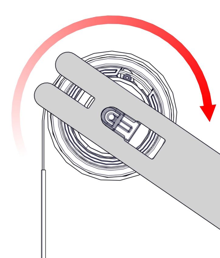
SECTION A | TOOLS AND ADDITIONAL ITEMS REQUIRED

PART A – TOOLS REQUIRED

•        Saw
•        Drill
•        Drill Bits – 2.5mm, 2.6mm, 3mm, 3.2mm & 4mm
•        Screw Driver – Philips Head
•        Scissors
•        Measuring Tape
•        Spirit Level

PART B – ADDITIONAL ITEMS REQUIRED (NOT SUPPLIED)

To install a Zipscreen, the following non-stocked items are required:
•        Fixings for Box/Open Brackets/Hardware (ensure appropriate fixings are used to suit application)
•        Trims to conceal packing (if required)

                                               Zipscreen Installation Manual | v4.7 | June 2021             Page. 3
                                            2021 ©Copyright All Rights Reserved Rollease Acmeda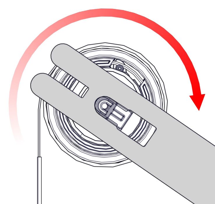
SECTION A | TOOLS AND ADDITIONAL ITEMS REQUIRED

 PART C – BLIND ITEMS REQUIRED

  BOX                                                                            COVER (FULL OR FASCIA COVER)
                                                                                 A 40mm (1.58”) offcut of the Box 120 Back is recommended
                                                                                 every 1200mm (47.24”) to support the Cover.

  NOTE: Ensure to pre-drill holes before fixing

  SIDE GUIDES
  SIDE GUIDES: SIDE FIX                           SIDE GUIDES: FACE FIX OPTION 1                            SIDE GUIDES: FACE FIX OPTION 2

                                       OR                                                              OR

                                                 BLIND                                                 RIVETS / SCREWS -
  OPEN BRACKETS
                                                                                                       QUANTITY AS REQUIRED

NOTE: Store Idler/Spring Adapter retaining
clip until required (can be left in adaptor as
shown)

  Page. 4                                           Zipscreen Installation Manual | v4.7 | June 2021
                                                 2021 ©Copyright All Rights Reserved Rollease Acmeda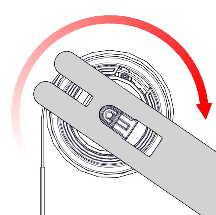
SECTION B | INSTALLATION

PART A – PREPARING INSTALLATION SPACE

STEP 1 – CHECK FOR OBSTRUCTIONS

Check for any obstructions that may interfere in installation.

E.g. If there is an architrave at the bottom of a post that the Zipscreen is to be installed into, ensure you prepare the space for the
installation.

This may mean that the installer needs to cut into the architrave to make room for the side rails.

STEP 2 – CHECK TOP OF INSTALLATION IS LEVEL

                                                                                IfD1un-even go to step 3D2

                                                                                If level go to step 4

                                                                                 D1                     D2

STEP 3 – PACK AND LEVEL TOP OF INSTALLATION TO SMALLEST DROP DIMENSION

                                                                                 D1                     D2
                                                                                D = Drop of Blind

                                                                                NOTE: In some instances, when the drop is level D1 & D2
                                                                                will not be equal as there is an uneven ground.

                                                                                Ensure the smallest value of D1 & D2 = Blind Drop (D
                                                                                specified in initial measurement)
           D1                       D2

           D1                       D2

           D1                       D2

                                                 Zipscreen Installation Manual | v4.7 | June 2021                            Page. 5
                                              2021 ©Copyright All Rights Reserved Rollease Acmeda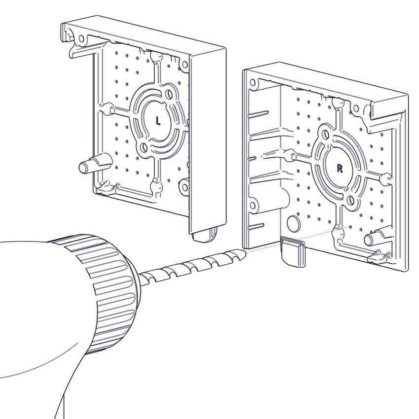
SECTION B | INSTALLATION

STEP 4 – CHECK HORIZONTAL INSTALLATION DIMENSION AT TOP, CENTRE & BOTTOM

                                                             W = Width of blind

                                                             If W1, W2, & W3 are equal or within10mm of each other, proceed to Step 5
                                                             for Side Fix applications, or Step 6 for Face Fix applications.

                                                             If W1, W2, & W3 are not equal or within10mm of each other, review
                                                             the scenarios outlined in Step 4 and determine if and where packing is
                                                             required.

                                                             When using face Fix U Mounting Rail, W3 must be less than or equal to W1.

                                                             The following steps describe scenarios when using L Fixing Rail in
                                                             application.

STEP 5 – PACK INSTALLATION WIDTH TO BLIND WIDTH MEASUREMENT
                                 SCENARIO                                                                  PACKING DETAILS

                                                                               Determine dimension x on each side

                                                                               If X1 or X2 is less than 10, no packing necessary (however, a
                                                                               square space will provide greater flexibility with the rest of
                                                                               the installation). If x is equal to or greater than 10, pack-
  W3 is greater than W1 and W2                                                 ing is required. Pack out the largest dimensions (W3) to be
                                                                               within 10mm of the smallest dimension (W1).
                                                                               Ensure W1 = Blind Width (Blind width is specified in initial
                                                                               check and measure) Proceed to Step 6 for Side Fix applica-
                                                                               tions, or Step 7 for Face Fix applications

                                                                               Pack space so that the top is equal to or within 10mm of the
                                                                               smallest dimension (W3)
                                                                               Ensure W3 = Blind Width
                                                                               (Blind width is specified in initial check and measure)

                       W1 is greater than W2 and W3
                                                                               Proceed to Step 6 for Side Fix applications, or Step 7 for
                                                                               Face Fix applications

                                                                               Pack space so largest dimension (W2) to be equal to or within 10mm of
                                                                               smallest dimension (W1 or W3). Ensure smallest dimension = Blind Width
                                                                               (Blind width is specified in initial check and measure)

                                                                               If W1 and W3 sizes are different, minor packing may also be
                                                                               required at these locations.
  W2 is greater than W1 and W3                                                 Proceed to Step 6 for Side Fix applications, or Step 7 for
                                                                               Face Fix applications

Page. 6                                              Zipscreen Installation Manual | v4.7 | June 2021
                                                  2021 ©Copyright All Rights Reserved Rollease Acmeda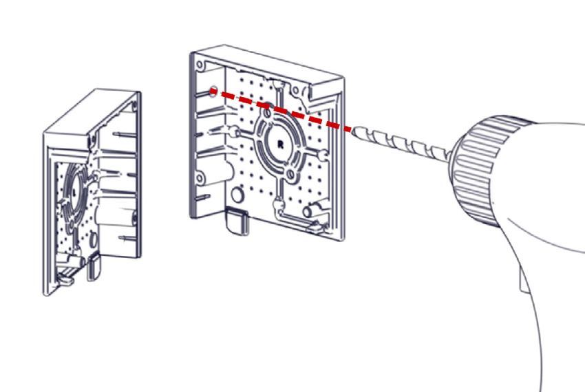
SECTION B | INSTALLATION

STEP 6 – CHECK SIDES OF INSTALLATION ARE LEVEL (FOR SIDE FIX APPLICATIONS ONLY)

                                SCENARIO                                                         PACKING DETAILS

                                                                       Determine dimension x on each side

                                                                       If X1 or X2 is less than 10, no packing necessary (however, a
                                                                       square space will provide greater flexibility with the rest of
                                                                       the installation).
 W3 is greater than W1 and W2
                                                                       If X1 or X2 is equal to or greater than 10, packing is
                                                                       required. Pack out the sides so they are level or within
                                                                                                      D1                                D2
                                                                       10mm of W1.
                                                                       Ensure the finished W1 width = Blind Width
                                                                       (Blind width is specified in initial check and measure)

STEP 7 – CHECK AND ENSURE THE INSTALLATION SPACE IS LEVEL & SQUARE

                                                                                                       D1                               D2

                                                                                                       D1                               D2

                                              Zipscreen Installation Manual | v4.7 | June 2021                              Page. 7
                                           2021 ©Copyright All Rights Reserved Rollease Acmeda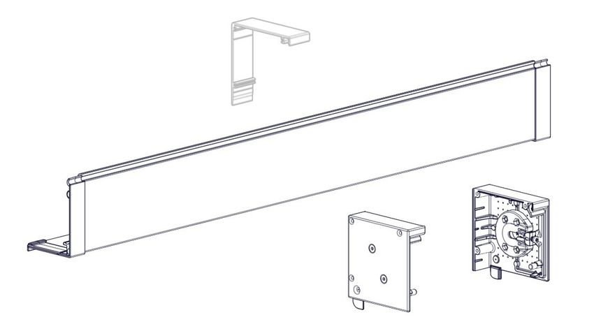
SECTION B | INSTALLATION

STEP 8 – IDENTIFY HIGHEST POINT ON FLOOR/GROUND

Take multiple readings to measure the highest point on floor/ground.

                Highest Point

Note: Whilst installing the shade (in the next sections), ensure that the base of the side guides should not be lower than the
measured highest point on floor/ground.

Page. 8                                         Zipscreen Installation Manual | v4.7 | June 2021
                                             2021 ©Copyright All Rights Reserved Rollease Acmeda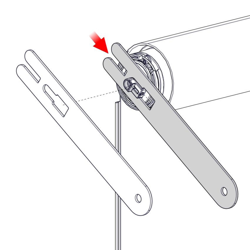
SECTION B | INSTALLATION
PART B – SPRING PRE-TENSIONING
STEP 1 – IDENTIFY NUMBER OF PRE-TURNS REQUIRED FOR BLIND SIZE
78mm Tube [F56 Weight Bar]
0.5 0.7 0.8 1.0 1.2 1.4 1.6 1.8 2.0 2.2 2.4 2.6 2.8 3.0 3.2 3.4 3.6 3.8 4.0 4.2 4.4 4.6 4.8 5.0 5.2 5.4 5.6 5.8
0.6 2 5 7 5 7 8 9 11 12 14 15 9 10 11 12 13 14 14 15 16 9 10 10 11 11 10 11 11 11 24
0.8 3 5 7 5 7 8 10 11 13 14 16 9 10 11 12 13 14 15 16 9 9 10 10 11 11 10 11 11 12 32
BOX 120 OR OPEN BRACKET SYSTEMS
1.0 4 5 7 5 7 8 10 11 13 14 16 10 11 11 12 13 14 15 16 9 10 10 11 11 12 11 11 11 12 40
1.2 4 5 7 5 7 8 10 11 13 15 16 10 11 12 13 14 15 15 16 9 10 10 11 11 10 11 11 12 12 48
1.4 5 4 7 5 7 8 10 12 13 15 17 10 11 12 13 14 15 16 17 9 10 10 11 12 10 11 11 12 12 56
1.6 6 4 7 5 7 8 10 12 14 15 9 10 11 12 13 14 15 16 17 9 10 11 11 12 11 11 12 12 13 63
1.8 7 4 7 5 7 8 10 12 14 16 9 10 11 12 13 15 16 17 18 10 10 11 11 12 11 11 12 12 13 71
2.0 7 4 7 5 7 8 10 12 14 16 9 10 12 13 14 15 16 17 9 10 10 11 12 12 11 12 12 13 13 79
2.2 8 4 7 5 7 9 11 13 15 17 9 11 12 13 14 15 16 18 9 10 11 11 12 11 11 12 12 13 14 87
2.4 9 4 7 5 7 9 11 13 15 17 10 11 12 13 14 16 17 9 9 10 11 11 10 11 11 12 13 13 14 95
2.6 9 4 7 5 7 9 11 13 15 18 10 11 12 14 15 16 8 9 10 10 11 10 10 11 12 12 13 - - 103
2.8 10 4 8 5 7 9 11 14 16 18 10 11 13 14 15 16 8 9 10 10 9 10 11 11 12 - - - - 111
3.0 11 4 8 5 7 9 12 14 16 18 10 11 13 14 16 8 8 9 10 9 9 10 11 11 - - - - - 119
OPEN BRKTS ONLY
3.2 11 5 7 9 12 14 17 19 10 12 13 15 7 8 8 9 8 9 10 10 - - - - - - - 126
3.4 12 5 7 10 12 14 17 19 11 12 13 6 7 8 9 8 8 9 10 - - - - - - - - 134
3.6 12 5 7 10 12 15 17 20 11 12 14 6 7 8 7 8 8 9 - - - - - - - - - 142
3.8 13 5 7 10 13 15 18 9 11 12 5 6 7 6 7 8 9 - - - - - - - - - - 150
4.0 14 5 - 10 13 16 18 10 11 13 5 6 6 6 7 8 - - - - - - - - - - - 158
- - - - - - - - - - - - - - - - - - - - - - - - -
20 28 32 40 48 56 63 71 79 87 95 103 111 119 126 134 142 150 158 166 174 182 189 197 205 213 221 229
PARAMETERS
Tube: 78 HD Aluminium Tube (includes 78 AL STD & 78 STEEL)
Fabric: 573gsm (19.36oz/yd²), 0.85mm Thick
Weight Bar: F56 HD External Weight Bar
LEGEND DESCRIPTION MAX SPRING ROTATIONS
Outside Product Specifications -
COMPACT RE01 Spring
25
COMPACT Spring requires Ultra-Lock or Bolt Lock.
Short RE01 Spring 25
Standard RE01 Spring 38
Heavy Duty RE01 Spring 31
X-Heavy RE01 Spring 25
Dual Heavy RE01 Springs 31 (Per Spring)
Externals Calculator Version: 1.04 (03-Nov-18)
Booster SF: 5
Title Nom. Spring Rate Low Tol % Low Range Upper Tol % Upper Range
COMPACT RE01 Spring 0.0550 100% 0.0000 0% 0.0550
Short RE01 Spring 0.0832 100% 0.0000 0% 0.0832
Standard RE01 Spring 0.0839 100% 0.0000 35% 0.1133
Heavy Duty RE01 Spring 0.1442 0% 0.1133 38% 0.1990
The above charts are indicative only and indicate the minimum number of pre-turns required. Due to variances in fabric weights,
X-Heavy RE01 Spring
Dual Heavy RE01 Springs
0.2534
0.2884
30%
0%
0.1774
0.2534
0%
500%
0.2534
1.7304
additional ballast weight and installations the optimum number of pre-turns will vary. Pre-turns can be adjusted during
0.00 0.001 0% 1.7304 0% 0.0010
installation. 0.00 0.0000 0% 0.0000 0% 0.0000
Zipscreen Installation Manual | v4.7 | June 2021 Page. 9
2021 ©Copyright All Rights Reserved Rollease Acmeda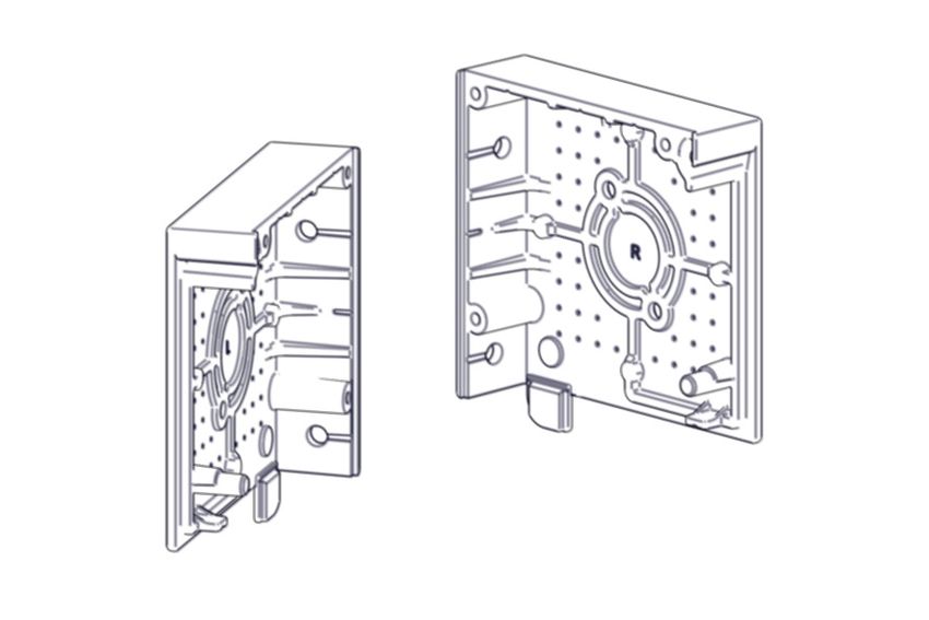
SECTION B | INSTALLATION
78mm Tube [F56+0.8kg/m ballast or F72 Weight Bar]
0.5 0.7 0.8 1.0 1.2 1.4 1.6 1.8 2.0 2.2 2.4 2.6 2.8 3.0 3.2 3.4 3.6 3.8 4.0 4.2 4.4 4.6 4.8 5.0 5.2 5.4 5.6 5.8
0.6 2 7 11 8 10 12 14 16 19 21 23 25 27 17 18 19 20 22 23 24 14 15 16 16 17 18 16 17 17 24
0.8 3 7 11 8 10 12 14 17 19 21 23 25 16 17 18 20 21 22 23 14 14 15 16 17 17 16 16 17 18 32
BOX 120 OR OPEN BRACKET SYSTEMS
1.0 4 7 11 8 10 12 15 17 19 21 24 26 16 17 19 20 21 23 13 14 14 15 16 15 15 16 17 17 18 40
1.2 4 7 11 8 10 12 15 17 19 22 24 27 16 17 19 20 22 12 13 14 15 15 14 15 15 16 17 17 18 48
1.4 5 7 11 8 10 13 15 17 20 22 25 27 16 18 19 21 12 12 13 14 15 14 14 15 16 16 17 18 18 56
1.6 6 7 11 8 10 13 15 18 20 23 25 15 17 18 19 11 12 13 13 14 13 14 14 15 16 17 17 18 19 63
1.8 7 7 11 8 10 13 15 18 21 23 26 15 17 18 20 11 12 13 14 12 13 14 15 15 16 17 18 18 19 71
2.0 7 7 11 8 10 13 16 18 21 24 14 16 17 19 10 11 12 13 12 12 13 14 15 16 16 17 18 19 - 79
2.2 8 7 11 8 10 13 16 19 21 24 14 16 17 9 10 11 12 11 12 13 13 14 15 16 17 17 18 - - 87
2.4 9 7 11 8 10 13 16 19 22 25 14 16 18 9 10 11 10 11 12 13 14 14 15 16 17 18 - - - 95
2.6 9 7 - 8 11 13 16 19 22 13 15 16 8 9 10 9 10 11 12 13 14 15 15 16 17 - - - - 103
2.8 10 7 - 8 - 14 17 20 23 13 15 16 8 9 10 10 10 11 12 13 14 15 16 16 - - - - - 111
3.0 11 7 - 8 - 14 17 20 11 13 15 7 9 10 9 10 10 11 12 13 14 15 16 - - - - - - 119
OPEN BRKTS ONLY
3.2 11 8 - 14 17 20 12 13 15 8 9 8 9 10 11 12 12 13 14 15 - - - - - - - 126
3.4 12 8 - 14 17 21 12 14 6 8 9 8 9 10 11 12 13 14 14 - - - - - - - - 134
3.6 12 8 - 14 18 21 12 14 6 8 7 8 9 10 11 12 13 14 - - - - - - - - - 142
3.8 13 - - 15 18 10 12 5 6 6 7 8 9 10 11 12 13 - - - - - - - - - - 150
4.0 14 - - 15 18 10 12 5 6 6 7 8 9 10 11 12 - - - - - - - - - - - 158
- - - - - - - - - - - - - - - - - - - - - - - - -
20 28 32 40 48 56 63 71 79 87 95 103 111 119 126 134 142 150 158 166 174 182 189 197 205 213 221 229
PARAMETERS
Tube: 78 HD Aluminium Tube (includes 78 AL STD & 78 STEEL)
Fabric: 573gsm (19.36oz/yd²), 0.85mm Thick
Weight Bar: F72 HD External Weight Bar or F56 + 0.8kg/m ballast
LEGEND DESCRIPTION MAX SPRING ROTATIONS
Outside Product Specifications -
COMPACT RE01 Spring
25
COMPACT Spring requires Ultra-Lock or Bolt Lock.
Short RE01 Spring 25
Standard RE01 Spring 38
Heavy Duty RE01 Spring 31
X-Heavy RE01 Spring 25
Dual Heavy RE01 Springs 31 (Per Spring)
Externals Calculator Version: 1.04 (03-Nov-18)
Booster SF: 5
Title Nom. Spring Rate Low Tol % Low Range Upper Tol % Upper Range
COMPACT RE01 Spring 0.0550 100% 0.0000 0% 0.0550
Short RE01 Spring 0.0832 100% 0.0000 0% 0.0832
Standard RE01 Spring 0.0839 100% 0.0000 35% 0.1133
Heavy Duty RE01 Spring 0.1442 0% 0.1133 38% 0.1990
X-Heavy RE01 Spring 0.2534 30% 0.1774 0% 0.2534
The above charts are indicative only and indicate the minimum number of pre-turns required. Due to variances in fabric weights,
Dual Heavy RE01 Springs 0.2884 0% 0.2534 500% 1.7304
0.00 0.001 0% 1.7304 0% 0.0010
additional ballast weight and installations the optimum number of pre-turns will vary. Pre-turns can be adjusted during
0.00 0.0000 0% 0.0000 0% 0.0000
installation.
Page. 10 Zipscreen Installation Manual | v4.7 | June 2021
2021 ©Copyright All Rights Reserved Rollease AcmedaSECTION B | INSTALLATION
STEP 2 – BEFORE PRE-TENSIONING, LOCK SPRING AT CONTROL END
RIGHT HAND
LEFT HAND
LEFT HAND SPRING LOCKED RIGHT HAND SPRING LOCKED
The booster head will now ‘click’ once The booster head will now ‘click’ once
per turn when rotated clockwise. per turn when rotated anti-clockwise.
(in direction of LH arrow) (in direction of RH arrow)
ONCE LOCKED, SPRING IS READY FOR PRE-TENSIONING.
STEP 3 – ENGAGE SPANNER ONTO PRE-TENSION HEAD
Slide Down to Engage
STEP 4 – HOLD TUBE AND PRE-TURN SPRING IN DIRECTION INDICATED ON LABEL
#Wraps + pre-turns must be less
than max spring rotations.
Do not exceed max spring rotations.
Pre-turn spring for number of times
indicated in Spring tensioning charts. A click
will be heard for each turn.
Dual spring systems are expected to have
equal pre-turns.
Note: Gradually increase the number of pre-
turns required. Only remove the pre-tension
spanner when the spring tension is held by
the internal mechanism, immediately after a LEFT HAND SPRING PRE-TENSION RIGHT HAND SPRING PRE-TENSION
‘click’ is heard. DIRECTION DIRECTION
Remove spanner when complete. PRE-TENSION DIRECTION IS OPPOSITE TO FABRIC ROLL.
Zipscreen Installation Manual | v4.7 | June 2021 Page. 11
2021 ©Copyright All Rights Reserved Rollease AcmedaSECTION B | INSTALLATION
PART C – COVER ASSEMBLY
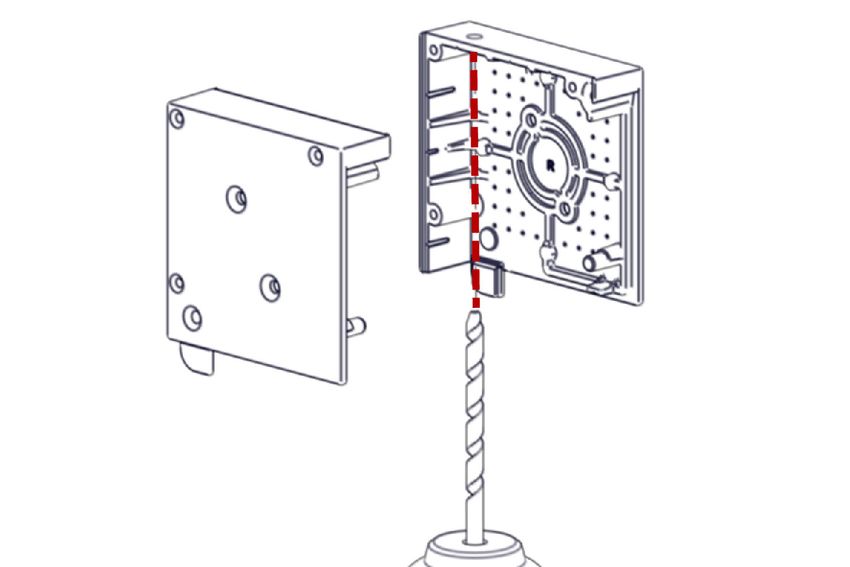
STEP 1 – DRILL CLEARANCE HOLES IN ‘END PLATE’ TO FACILITATE INSTALLATION FIXINGS
FACE FIX INSTALLATION OPTION
TOP FIX INSTALLATION OPTION
RECESS FIX INSTALLATION OPTION
10 20
10
20
NOTE: Holes are marked on end plate for drilling,
For balanced installation drill holes at corresponding opposite sides of plate.
Page. 12 Zipscreen Installation Manual | v4.7 | June 2021
2021 ©Copyright All Rights Reserved Rollease AcmedaSECTION B | INSTALLATION
PART D – BOX INSTALLATION
STEP 1 – INSTALL BOX TO WALL/CEILING
FACE FIX TOP FIX SIDE FIX
Note: Use appropriate fixings to suit application. Ensure Box is Aligned and Level.
PART E – COVER INSTALLATION
STEP 1 – INSTALL END PLATES TO WALL/CEILING USING APPROPRIATE FIXINGS TO SUIT
APPLICATION
FACE FIX TOP FIX SIDE FIX
Note: 1. Use appropriate fixings to suit application. 2. Ensure End Plates are Aligned and Level. 3. Measure brackets end to end
to confirm measurement is correct
Zipscreen Installation Manual | v4.7 | June 2021 Page. 13
2021 ©Copyright All Rights Reserved Rollease AcmedaSECTION B | INSTALLATION
PART F – OPEN BRACKET INSTALLATION
STEP 1 – INSTALL BRACKETS TO WALL/CEILING USING APPROPRIATE FIXINGS TO SUIT
APPLICATION
FACE FIX SIDE FIX TOP FIX
Note: 1. Use appropriate fixings to suit application. 2. Ensure brackets are Aligned and Level. 3. Measure brackets end to end to
confirm measurement is correct
PART G – BLIND INSTALLATION
STEP 1 – INSERT BLIND INTO BOX
User effort will be required to push the booster head/Idler pin into the adapter,
a noticeable “click” will indicate that the component is correctly located.
Page. 14 Zipscreen Installation Manual | v4.7 | June 2021
2021 ©Copyright All Rights Reserved Rollease AcmedaSECTION B | INSTALLATION
STEP 2 – INSERT RETAINER CLIP MKII INTO IDLER ADAPTER
IDLER END CONTROL END
Ensure pin is clipped in securely SPRING ONLY: Insert Retainer Clip MKII at spring end
Tighten the Screw SPRING ONLY: Insert Retainer Clip MKII at spring end
and tighten the screw to secure.
STEP 3 – UNLOCK PRE-TENSION HEAD AT STEP 4 – FEED THROUGH MOTOR CABLE
SPRING END (FOR SPRING ONLY) (FOR MOTOR ONLY)
Unlock spring pre-tension head by switching the locking
latch.
When the weight bar is pulled down, the tension in the
spring will be released.
Zipscreen Installation Manual | v4.7 | June 2021 Page. 15
2021 ©Copyright All Rights Reserved Rollease AcmedaSECTION B | INSTALLATION
STEP 5 – RUN BLIND DOWN + CENTRE
STEP 6 – TEST BLIND OPERATION
For spring operation, blind should creep up slowly when pulled down.
If blind does not creep up, add more pre-turns. For motor operation,
ensure wiring is correct and motor is operating correctly.
For gear operation, ensure operation is smooth.
Page. 16 Zipscreen Installation Manual | v4.7 | June 2021
2021 ©Copyright All Rights Reserved Rollease AcmedaSECTION B | INSTALLATION
PART H – ADJUSTING PRE-TURNS (SPRING OPERATED BLINDS ONLY)
STEP 1 – LOCK PRE-TENSION HEAD STEP 2 – REMOVE RETAINER CLIP FROM
BEFORE REMOVING RETAINER CLIP ADAPTER
Note: Ensure springs are locked by lifting weight bar until Loosen the screw then lever the Retainer Clip MKII outwards.
fabric bunches up.
STEP 3 – REMOVE TUBE AND ADD ADDITIONAL PRE-TURNS AS REQUIRED
Note: Gradually increase the number of pre-turns required. Only remove the pre-tension spanner when the spring tension is
held by the internal mechanism, immediately after a ‘click’ is heard.
#Wraps + pre-turns must be less than max spring rotations. Do not exceed max spring rotations.
LEFT HAND SPRING PRE-TENSION RIGHT HAND SPRING PRE-TENSION
DIRECTION DIRECTION
PRE-TENSION DIRECTION IS OPPOSITE TO FABRIC ROLL.
STEP 4 – RE-INSTALL AND TEST BLIND OPERATION
Re-install tube assembly into Bracket Adaptor and secure
Retainer Clip prior to operating shade.
Unlock spring pre-tension head by switching the locking latch.
When the weight bar is pulled down, the tension in the spring
will be released.
For spring operation, the weight bar should creep up slowly
when pulled down.
Zipscreen Installation Manual | v4.7 | June 2021 Page. 17
2021 ©Copyright All Rights Reserved Rollease AcmedaSECTION B | INSTALLATION
PART I – SIDE GUIDE INSTALLATION
STEP 1 – MARK OUT SIDE GUIDE POSITION AND ALIGN RAIL (FOR OPEN BRACKET ONLY)
FACE FIX TOP FIX
STEP 2 – MOUNT L-FIXING RAIL TO WALL ON BOTH SIDES (FOR FACE FIX ONLY)
500mm (19.69”)
Use an off cut of the U mounting rail to install the L-fixing rail at the correct distance from the end plate.
STEP 3 – INSERT U-MOUNTING RAIL/FACE FIX U-MOUNTING RAIL
L-Fixing Rail + U-Mounting Rail + Face Fix U-Mounting Rail +
ear of end plate ear of end plate
Locate ear of end plate with U-mounting rail
Page. 18 Zipscreen Installation Manual | v4.7 | June 2021
2021 ©Copyright All Rights Reserved Rollease AcmedaSECTION B | INSTALLATION
STEP 4 – SECURE U-MOUNTING RAIL TO SIDE FIX SURFACE OR L-FIXING RAIL
FACE FIX: L – FIXING RAIL
500mm (19.69”)
(0.16”)
FACE FIX: U – MOUNTING RAIL SIDE FIX
(0.16”)
STEP 5 – REMOVE THE STOPS FROM THE FUNNEL IN THE INNER RAILS
Use flat head screw driver to pry both stops out.
Zipscreen Installation Manual | v4.7 | June 2021 Page. 19
2021 ©Copyright All Rights Reserved Rollease AcmedaSECTION B | INSTALLATION
STEP 6 – SWING INNER RAIL INTO THE U MOUNTING RAIL ON AN ANGLE ON BOTH SIDES
• Ensure weight bar is 50mm (1.97”)-100mm (3.94”) from box
• Feed zip into funnel
STEP 7 – PUT STOPS BACK INTO FUNNEL
If there is inadequate access to the back of the blind to attach stops, add only one to the front of the blind on both ends
STEP 8 – OPERATE BLIND MULTIPLE TIMES TO ALLOW INNER RAIL TO MOVE INTO NATURAL
POSITION
The inner rail should sit parallel with the zip to avoid strain
or jamming of blind during operation.
Ensure the zip is running inside the inner rail on both sides.
When using the Ultra-Lock, the Latch Housings must be
level with each other to ensure the Ultra-Lock Pins lock
simultaneously.
Adjust the position of the Inner Rails as required.
Page. 20 Zipscreen Installation Manual | v4.7 | June 2021
2021 ©Copyright All Rights Reserved Rollease AcmedaSECTION B | INSTALLATION
STEP 9 – SECURE THE INNER RAILS
150 mm (5.91”) (MIN)
(2.05”)
Screw/ Rivet inner rail at central position.
Pre-drill 4mm holes for rivets.
Rivet: Dome head, body diameter 4.0mm
Grip range: 4.8 – 6.4mm stainless steel
Run the blind up and secure the inner rails at the Tek screws can also be used to secure
top of the blind on both sides Inner rail into place.
(2.44”)
(1.65”)
The overall dimension of the U mounting rail and Inner
75 mm (2.95”) (MIN)
rail must be between 42mm (1.65”) - 62mm (2.44”).
Run the blind down and secure the inner rail at the
bottom on both sides
Ensure inner rail is level before fixing
(2.05”)
(1.69”)
500 mm (19.69”) (MAX)
The overall dimension when using Face Fix U Mounting
Rail and inner rail is 43mm (1.69”) – 52mm (2.05”).
Move the blind to the next fixing position and secure
the inner rails along the length of the blind on both
sides. Do not force the inner rail; it should be in its
natural position.
Zipscreen Installation Manual | v4.7 | June 2021 Page. 21
2021 ©Copyright All Rights Reserved Rollease AcmedaSECTION B | INSTALLATION
STEP 10 – TEST OPERATION AND APPEARANCE OF BLIND
IMPORTANT:
The distance between the weight bar end cap and the
Check inner rails are level and parallel edge of the inner rail should always be approximately
3mm (0.12”)
STEP 11 – (NOT FOR ULTRA-LOCK) – SET MOTOR LIMITS (MOTOR CONTROL ONLY)
TOP LIMIT: Set top limit as required (should be as close BOTTOM LIMIT: Set to the lowest point possible. Ensure
to the box as possible) seal is compressed as much as possible.
Page. 22 Zipscreen Installation Manual | v4.7 | June 2021
2021 ©Copyright All Rights Reserved Rollease AcmedaSECTION B | INSTALLATION
PART J – ULTRA-LOCK MOTOR SETTINGS
STEP 1 – INITIAL SETUP
PAIR MOTOR WITH CONTROLLER
Select channel on Hold P1 button on motor Hold STOP on controller.
controller. head.
IMPORTANT Motor Response Motor Response
Consult user manual for your
controller for information on Approx.
selecting channel.
Motor is now in step mode and ready for setting limits.
CHECK FOR MOTOR DIRECTION
To check travel direction of shade, press UP or DOWN To reverse shade direction, hold both UP and DOWN.
on controller. .
Until the motor responds.
Quick Press = Step
Long Press = Continuous Travel
Motor Response
Approx.
IMPORTANT
Damage to shade may occur when operating motor
prior to setting limits. Attention should be given.
IMPORTANT
Reversing motor direction using this method is only
possible during initial set-up.
Zipscreen Installation Manual | v4.7 | June 2021 Page. 23
2021 ©Copyright All Rights Reserved Rollease AcmedaSECTION B | INSTALLATION
STEP 2 – SET UPPER LIMIT
Setting limits with this method is only possible during initial set up. Refer to Part L for adjusting motor limits.
Move shade to the desired highest position by pressing To save upper limit, hold UP and STOP.
the UP button on controller.
IMPORTANT Motor Response
Cycle shade up and down prior to setting limits to
settle fabric.
Approx. 5 SECS
IMPORTANT
Initial set-up is not complete.
After setting limits, motor will automatically exit from initial set-up mode.
STEP 3 – SET LOWER LIMIT (LOCK POSITION)
Setting limits with this method is only possible during initial set up. Refer to Part J for adjusting motor limits.
IMPORTANT
The motor lower limit must be set correctly between the locking & unlocking position. Jog the motor down to find the lock
position (Jog until you hear BOTH pins click), then set the lower limit.
Move shade to lock position by pressing the DOWN To save lower limit, hold DOWN and STOP.
button on controller.
Motor Response
Approx. 5 SECS
Page. 24 Zipscreen Installation Manual | v4.7 | June 2021
2021 ©Copyright All Rights Reserved Rollease AcmedaSECTION B | INSTALLATION
STEP 4 – ACTIVATE FABRIC TENSION MODE
Once the bottom limit is set, FT Mode will need to be activated to operate the Ultra-Lock.
Press P2 on controller. Press UP on controller. Press UP on controller.
FT MODE:
Motor Response
NO FT MODE:
Motor Response
IMPORTANT
Initial setup is complete. You may now operate the shade normally.
PART K – ULTRA-LOCK OPERATION (MOTOR OPERATION)
STEP 1 – LOCKING
Press DOWN on the controller. The motor will lower the weight bar to the set bottom limit, then automatically tension the fabric.
Note: Make sure that the FT mode is turned ON whilst locking and unlocking the blind.
STEP 2 – UNLOCKING
Press UP on the controller. The motor will lower the weight bar past the bottom limit to unlock, then raise the weight bar
continuing to the upper limit.
Note: Make sure that the FT mode is turned ON whilst locking and unlocking the blind. Refer to step 4 for instructions.
Zipscreen Installation Manual | v4.7 | June 2021 Page. 25
2021 ©Copyright All Rights Reserved Rollease AcmedaSECTION B | INSTALLATION
PART L – ADJUSTING MOTOR LIMITS
STEP 1 – ADJUST UPPER LIMIT
Move shade to the desired
Hold UP and STOP on To save upper limit, hold UP and
highest position by pressing the
controller. STOP.
UP button.
Motor Response Motor Response
Approx. 5 SEC S
Approx. 5 SEC S
STEP 2 – ADJUST LOWER LIMIT (LOCK POSITION)
IMPORTANT
The motor lower limit must be set correctly between the locking & unlocking position. Jog the motor down to find the lock
position (Jog until you hear BOTH pins click) then set the lower limit.
Hold DOWN and STOP on Move shade to the desired To save lower limit, hold DOWN
controller. lowest position by pressing the and STOP.
DOWN button.
Motor Response Motor Response
Approx. 5 SEC S Approx. 5 SEC S
Page. 26 Zipscreen Installation Manual | v4.7 | June 2021
2021 ©Copyright All Rights Reserved Rollease AcmedaSECTION B | INSTALLATION
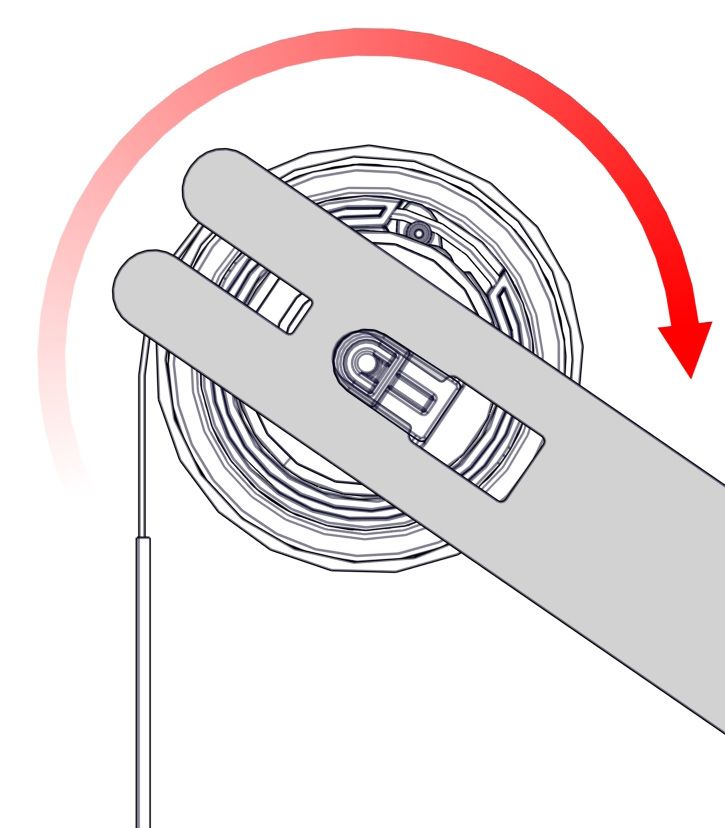
PART M – ULTRA-LOCK OPERATION (MANUAL OPERATION)
SPRING CONTROL
LOCKING
STEP 1 - LOWER THE WEIGHT BAR TOWARDS THE LOCK UNTIL YOU HEAR IT CLICK ONCE
If 2 ‘clicks’ are heard the weight bar has been lowered into the ‘unlock’ position. Raise the weight bar and try again to lock.
Click Click
STEP 2 - RELEASE THE WEIGHT BAR
UNLOCKING
STEP 1 - LOWER THE WEIGHT BAR ALL THE WAY DOWN PAST THE LOCKING POINT
STEP 2 - RAISE THE WEIGHT BAR
Zipscreen Installation Manual | v4.7 | June 2021 Page. 27
2021 ©Copyright All Rights Reserved Rollease AcmedaSECTION B | INSTALLATION
CRANK CONTROL
LOCKING
STEP 1 – ROTATE THE CRANK TO LOWER THE WEIGHT BAR TOWARDS THE LOCK UNTIL YOU
HEAR IT CLICK ONCE
If 2 ‘clicks’ are heard the weight bar has been lowered into the ‘unlock’ position. Raise the weight bar and try again to lock.
Click Click
STEP 2 – ROTATE THE CRANK IN THE OPPOSITE DIRECTION TO TENSION THE WEIGHT BAR
UNLOCKING
STEP 1 - ROTATE THE CRANK TO LOWER THE WEIGHT BAR ALL THE WAY DOWN PAST THE
LOCKING POINT
STEP 2 - ROTATE THE CRANK IN THE OPPOSITE DIRECTION TO RELEASE THE WEIGHT BAR
Page. 28 Zipscreen Installation Manual | v4.7 | June 2021
2021 ©Copyright All Rights Reserved Rollease AcmedaSECTION B | INSTALLATION
PART N – WEIGHT BAR SB07 LATCH INSTALLATION
STEP 1 – BRING WEIGHT BAR TO DESIRED LOCKED POSITION
Ensure shaft of the lock is retracted
STEP 2 – SECURE LATCH TO U-MOUNTING RAIL
Align lip of latch to U-Mounting Rail
Zipscreen Installation Manual | v4.7 | June 2021 Page. 29
2021 ©Copyright All Rights Reserved Rollease AcmedaSECTION B | INSTALLATION
STEP 3 – ADD ADDITIONAL LATCHES (IF REQUIRED)
PART O – INSERT BOX / COVER
STEP 1 – SWING BOX COVER INTO BOX STEP 2 – SECURE COVER AT BOTH ENDS
TOP AND CLIP INTO PLACE
Page. 30 Zipscreen Installation Manual | v4.7 | June 2021
2021 ©Copyright All Rights Reserved Rollease AcmedaSECTION C | INSTALLATION SCENARIOS
PART A – MULTIPLE BLINDS INSTALLED SIDE BY SIDE ON A FACE FIX INSTALL
STEP 1 – MARK OUT CORRECT POSITION WHERE COMPLETE FACE FIX BLINDS ARE TO BE
INSTALLED
It is important to install the blinds so that they match the initial measure.
STEP 2 – INSTALL BOX OR BRACKETS FOR BLIND 2
BLIND 2
STEP 3 – INSTALL L FIXING RAILS FOR BLIND 2
BLIND 2
STEP 4 – ENSURE L FIXING RAILS ARE AT THE CORRECT WIDTH FOR BLIND 2
Adjust L fixing rails if required. If blind 02 occupies installation space allocated to blind 1 or blind 3, operational or
installation problems will occur with these blinds.
Zipscreen Installation Manual | v4.7 | June 2021 Page. 31
2021 ©Copyright All Rights Reserved Rollease AcmedaSECTION C | INSTALLATION SCENARIOS
STEP 5 – INSTALL BOX OR BRACKETS FOR BLIND 1 & 3
STEP 6 – INSTALL L FIXING RAILS FOR BLIND 1 & 3
STEP 7 – ENSURE L FIXING RAILS ARE AT THE CORRECT WIDTH FOR BLINDS 1 & 3
Adjust L fixing rails and box or bracket installation if required.
STEP 8 – ATTACH U MOUNTING RAILS ON BLINDS 1, 2 & 3
Rivet U Mounting rails to L fixing rails to all 3 blinds
Page. 32 Zipscreen Installation Manual | v4.7 | June 2021
2021 ©Copyright All Rights Reserved Rollease AcmedaSECTION C | INSTALLATION SCENARIOS
STEP 9 – COMPLETE BLIND INSTALLATION FOR BLIND 2
Ensure blind is correct width as specified in initial measure.
STEP 10 – COMPLETE BLIND INSTALLATION FOR BLIND 1 & 3
Ensure blind is correct width as specified in initial measure.
FOR MORE THAN 3 BLINDS
Apply same principles outlined in previous steps when there are several blinds side by side
Zipscreen Installation Manual | v4.7 | June 2021 Page. 33
2021 ©Copyright All Rights Reserved Rollease AcmedaSECTION D | TROUBLESHOOTING
NO. PROBLEM CAUSE SOLUTION
Not enough tension in side guides Check inner rails are level & parallel. If required, adjust
position of Inner Rail within U-Mounting Rail.
1 Prominent smile across fabric
Ensure fabric is assembled straight onto tube and weight
Fabric is not installed straight
bar.
Blind rolled up for extended This occurrence is inherent to roller systems and is more
period of time prevalent in some fabrics. Leave blind down for 1-4 hours –
most ripples should disappear.
Remove rivets around the ripple area and reposition inner
Fabric not central to system
rail and secure
Check fabric is centred with system. If the fabric is not cen-
tred with the system, centre the fabric. The Side Rails may
need to be removed to correct. If fabric cannot be centred,
check scallop in fabric is large enough for installation
Too much tension in inner rails (refer to Assembly manual for scallop sizes). If the fabric at
the scallop is flush with the edge of the tube and the fabric
cannot move sideways any further, increase size of scallop
in fabric.
Check actual installation width dimension matches the
measured blind width.
If the installation width does not match the measured blind
width:
• Correct installation width to match measured blind width
or
• Correct fabric width to correct size (based on actual
Fabric is too wide for installation installation width)
Note: Tube and weight bar may also require correcting.
If the installation width matches the measured blind width:
Check overall fabric width from external zip edge to external
2 Ripples along sides of fabric
zip edge and ensure it is W-66mm (W being completed blind
width).
If required, correct fabric width.
Refer to product specs. Add ballast.
Note: for spring operated blinds, the number of pre-turns
Not enough weight in weight bar.
will most likely need to be increased.
It is more common for there to be some ripples in spring
operated blinds.
Spring operated blinds
To reduce the number of ripples evident, pull the blind down
softly and lock into position.
Not enough pre-turns in spring Increase number of pre-turns on spring.
Check overall width of U-mounting rail and inner rail is
within 42-62mm.
Check inner rails are level & parallel. If either of the above
Installation is not square checks are not in accordance with specifications, the instal-
lation space requires additional packing. The side rails or
entire systems may need to be removed to correct.
Page. 34 Zipscreen Installation Manual | v4.7 | June 2021
2021 ©Copyright All Rights Reserved Rollease AcmedaSECTION D | TROUBLESHOOTING
NO. PROBLEM CAUSE SOLUTION
Fabric permanently damaged due to
Replace the fabric and ensure it is handled
inadequate handling during assembly,
with care.
transportation, installation or use
Ensure fabric is assembled straight onto tube
Fabric is not installed straight
and weight bar.
Cut new fabric skin and weld zip onto fabric
3 Small ripples close to weld Welding temperature is too high on zip ensuring temperature is not too hot.
Refer Assembly manual for welding tips.
Check there is always approximately 3mm
(0.12”) gap between Weight Bar End Cap and
Inner Rail.
If there is insufficient clearance, check:
• Actual installation width dimension matches
the measured blind width
• The weight bar length is cut in accordance
with the deductions outlined by Rollease
Acmeda
Weight bar end cap hits Inner Rail
If the installation width does not match the
4 Blind gets jammed half way down measured blind width:
• Correct installation width to match measured
blind width
or
• Trim weight bar length to correct size (based
on actual installation width)
Note: Tube and fabric may also require cor-
recting
Ensure fabric is assembled straight onto tube
Fabric is not installed straight
and weight bar.
5 Spring operated blind is heavy to push up Not enough pre-turns Increase number of pre-turns on spring.
Ensure Spring head is unlocked on both ends
Spring operated blind will not retract the Spring pre-tension Idler has not been
6 of system.
screen un-locked.
Motor rotates blind continuously whilst a
This occurrence is inherent to the motorised
wind gust causes additional friction in In-
system and no damage will be caused as a
ner Rail and stops blind momentarily.
result. If undesired, avoid operating blind in
When force of wind is reduced, the addi-
Motorised blind jolts during operation windy conditions.
7 tional friction is removed and blind drops.
Add ballast to weight bar.
Not enough weight in weight bar
Check actual installation width dimension
matches the measured blind width.
If the installation width does not match the
measured blind width:
• Correct installation width to match measured
blind width
Cannot install inner rail into
8 Weight bar length is too long or
blind to feed zip
• Trim weight bar length to correct size (based
on actual installation width)
Note: Tube and fabric may also require cor-
recting
Zipscreen Installation Manual | v4.7 | June 2021 Page. 35
2021 ©Copyright All Rights Reserved Rollease AcmedaSECTION D | TROUBLESHOOTING
NO. PROBLEM CAUSE SOLUTION
Check actual installation drop dimension matches the
measured blind drop.
If the installation drop does not match the measured blind
drop:
• Correct installation drop to match measured blind drop
Inner rail length is too long or
• Trim inner rail length to correct size (based on actual
installation
width)
Note: U-mounting rail and L-fixing channel may also
require correcting
SB07 Weight Bar lock doesen’t Latch has not been secured in
9 Re-install latch so shaft locates into latch.
locate into latch correct position
Box is not level, thus weight bar appears Ensure box is level.
uneven
Check inner rails are level & parallel. If the inner rails
are not level and parallel remove rivets from U-mounting
Inconsistent friction along inner rails channel, reposition inner rail to reduce tension and re-
secure inner rail.
10 Uneven weight bar
Motorised blind jolts during operation See Point 7
This occurrence is inherent to Zipscreen and there isn’t
Zip overturns on itself
currently a solution.
Ensure fabric is assembled straight onto tube and weight
Fabric is not installed straight
bar.
The Automate FT motor Impact Detection
Put the blind up or down, increasing the distance from the
function isn’t active in the first 20cm from
limits and verify if the motor retracts the blind when an
the upper limit and in the last 20cm from
Impact Detection function of obstacle is detected.
11 the lower limit.
Automate FT motor is not active.
Impact Detection function has been deacti- Press P2, Down & Down on the remote and check the
vated during motor installation. functionality of Impact Detection again.
Note: For all Automate FT15 Motor information visit the Automate website:
https://www.automateshades.com/resource/programming-instructions-ft-motors/
Page. 36 Zipscreen Installation Manual | v4.7 | June 2021
2021 ©Copyright All Rights Reserved Rollease AcmedaDOCUMENT CHANGE NOTES
REVISION CHANGES
v4.7 Clarified information for pre-tensioning & adjustment of a RH Spring Control. (See pages 11, 17)
Zipscreen Installation Manual | v4.7 | June 2021 Page. 37
2021 ©Copyright All Rights Reserved Rollease AcmedaYou can also read