Bluetooth Light Module - LM-BT-16-4 V1.00 - BEIER-Electronic
←
→
Page content transcription
If your browser does not render page correctly, please read the page content below
GB                                                Bluetooth Light Module LM-BT-16-4

                Operating Instructions

                Bluetooth
              Light Module
               LM-BT-16-4
                  V1.00

                               BEIER-Electronic
             Winterbacher Str. 52/4, 73614 Schorndorf - Weiler
                Telefon 07181/46232, Telefax 07181/45732
                   eMail: modellbau@beier-electronic.de
             Internet: http://www.beier-electronic.de/modellbau

21.05.2021                    BEIER-Electronic                                   1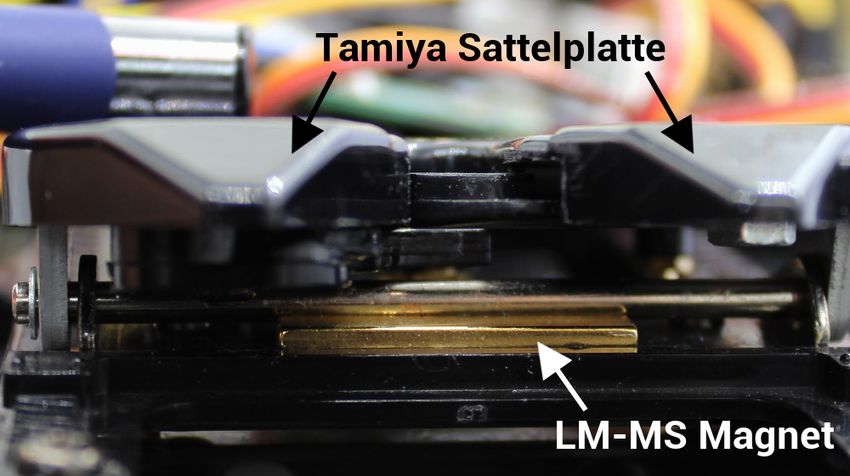
GB                                                                                 Bluetooth Light Module LM-BT-16-4

Table of Contents
Table of Contents ....................................................................................................... 2
Description.................................................................................................................. 3
Safety advisory ........................................................................................................... 4
Technical data ............................................................................................................ 4
Pin assignment ........................................................................................................... 5
Wiring diagram ........................................................................................................... 6
Supply voltage connection .......................................................................................... 6
Connection of Bluetooth transmitter ........................................................................... 6
Connection of outputs ................................................................................................ 8
Connection of servos .................................................................................................. 9
Connection of motor ................................................................................................... 9
Connection of switch for manual motor control ........................................................ 10
Connection of data cable K-USB-2........................................................................... 10
Road train ................................................................................................................. 10
Connecting and disconnecting Bluetooth ................................................................. 11
Switching outputs ..................................................................................................... 12
Special light functions at outputs 13 - 16 .................................................................. 14
Controlling the servo outputs .................................................................................... 15
Controlling the motor output ..................................................................................... 16
LEDs on LM-BT-16-4................................................................................................ 16
PC software „LM-Teacher“ ....................................................................................... 17
Using software „LM-Teacher“ ................................................................................... 18
Diagnosis .................................................................................................................. 20
Firmware update....................................................................................................... 22

2                                                   BEIER-Electronic                                             21.05.2021
GB                                                         Bluetooth Light Module LM-BT-16-4

Description

The Bluetooth light module LM-BT-16-4 is an expansion module for the modules
USM-RC-2 and SFR-1.

The light module can be used to control lights, servos and motors on a (truck) trailer
or semitrailer. The signals are transmitted wirelessly via a Bluetooth module.
Connecting cables from the towing vehicle to the trailer are therefore not necessary.
A separate battery is required in the trailer or semitrailer for the supply voltage of the
light module.

The LM-BT-16-4 has 16 switching outputs for connecting the lighting (e.g. lamps and
LEDs). The light signals are passed on from the main module to the light module.
For the switching outputs 13 - 16, special functions such as a 1- and 4-channel all-
round light, a 4-channel running light and different flashing effects can be selected. A
detailed assignment of the switching outputs in combination with the various modules
can be found on page 12.

A motor output can be used for direct control of e.g. trailer supports, ramps or tipping
movements. An optional switch for controlling the motor output manually can be
connected to the module as well.

There are also 4 servo outputs to control (servo) movements. Applications for this
are e.g. trailer supports, the locking and unlocking of a seat post, steerable axles, or
tipping movements. Speed controllers can be connected to the servo outputs to
control additional motors.

When delivered, the light module is ready for operation with the standard settings.
With the LM-Teacher software, many settings can be adjusted and additional options
can be selected. For this purpose, the light module is connected to a Windows PC
with the data cable K-USB-2.

In order to be able to control the LM-BT-16-4 via the SFR-1 or the USM-RC-2, the
light module must be activated in the sound teachers of the main modules. For this,
at least version V1.30 of the SFR-1 Sound-Teacher and version V1.80 of the USM-
RC-2 Sound-Teacher are required.

21.05.2021                           BEIER-Electronic                                      3

GB                                                       Bluetooth Light Module LM-BT-16-4

Safety advisory

     •   Read these operating instructions carefully before activation and keep them
         on hand for future usage!
     •   The integrated circuits on the light module are sensitive to electrostatic
         charges. You must “discharge” yourself (e.g. by touching a heater or another
         grounded device) before touching any component.
     •   The light module should only be operated with the supply voltage specified in
         the technical data.
     •   Wiring work may only be conducted in a non-energized state.
     •   Children under the age of 14 are not permitted to operate the light module.

Technical data

Supply voltage (Ub):               6 – 12 V DC
Current consumption:               Quiescent current: approx. 25mA
Switching outputs:                 16 pieces (minus-switching, N-channel MOSFET),
                                   max: 1.5 A per output, the total current of all
                                   outputs must not exceed 3,0 A.
Light functions:                   • 1:1 copy of 16 outputs of SFR-1
                                   • 1- or 4-channel all-round light
                                   • 4 different flashers
                                   • 4-channel running light
Servo outputs:                     4 pieces (1,000 - 2,000 ms),
                                   max. current consumption of servos: 1 A (short
                                   time 4 A)
Motor output:                      1 piece,
                                   max. current consumption of motor: 2 A (short time
                                   3 A)
Additional ports:                  • Magnet sensor
                                   • Switch to control motor manually
                                   • Data cablel / Bluetooth transmitter for a Road-
                                      Train
Permissible ambient                0 – 60° C
temperature:
Permissible relative air           Max. 85 %
humidity:
Dimensions:                        58 x 44 x 17 mm
Weight:                            26 g

4                                    BEIER-Electronic                          21.05.2021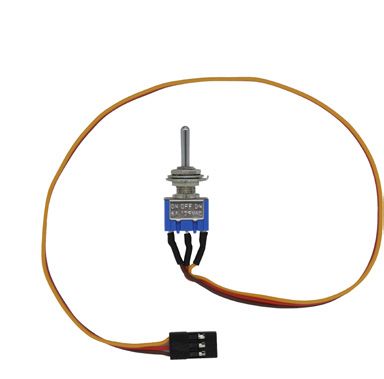
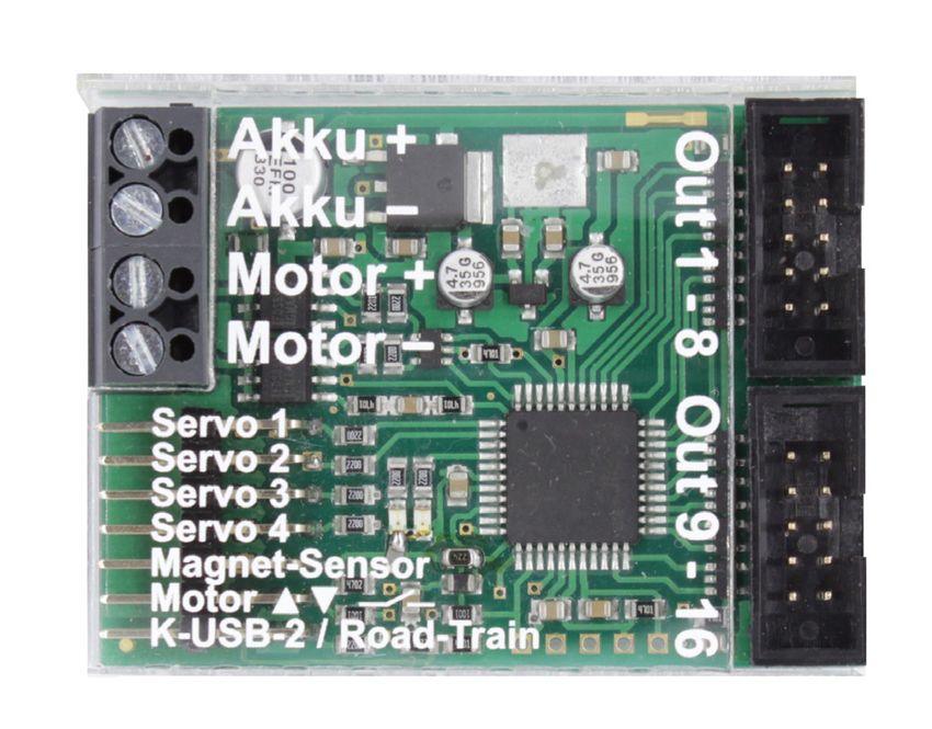
GB                                                    Bluetooth Light Module LM-BT-16-4

Pin assignment

Connections at light module:
X1/+    Battery + (6 – 12 V)
X1/-    Battery -
X2/+    Motor +
X2/-    Motor -
X3      Outputs 1 - 8
X4      Outputs 9 - 16
X5/1    Servo 1
X5/2    Servo 2
X5/3    Servo 3
X5/4    Servo 4
X5/5    Magnetic sensor
X5/6    Switch to control motor manually
X5/7    Data cable K-USB-2 / Bluetooth transmitter for a Road train

21.05.2021                        BEIER-Electronic                                   5
GB Bluetooth Light Module LM-BT-16-4
Wiring diagram
brown
Output 1
red
4A Output 2
orange
Output 3
+ yellow
Output 4
green
Battery Output 5
6 - 12 V blue
Output 6
purple
- Output 7
grey
Output 8
Motor white / black
(e.g. ramps, M
trailer supports) Outputs
minus switching
brown
Servo
Servo 1
Output 9
red
Output 10
orange
Servo
Servo 2 Output 11
yellow
Output 12
green
Output 13
Servo
Servo 3 Data cable /
K-USB-2 blue
Bluetooth transmitter for road train Output 14
purple
Output 15
Servo
Servo 4 grey
Motor up / down Output 16
white / black
Magnet sensor
All wiring work must be conducted while power supply is turned off!
Supply voltage connection
The LM-BT-16-4 requires a DC voltage of 6 - 12 V (e.g. a battery) for supply voltage.
This is connected to terminal X1. Please pay attention to the correct polarity!
Reverse polarity can destroy the module!
The cable cross-section for the supply voltage should be as large as possible (0.75
mm² - 1.5 mm²).
In addition, a switch for switching off the light module and a fuse with 4 A should also
be installed in the supply line (positive line).
Connection of Bluetooth transmitter
Bluetooth transmission:
The prerequisite for the function of the light module LM-BT-16-4 is a sound module
USM-RC-2 or a sound speed controller SFR-1! Operation with other sound modules /
speed controller is not possible.
The light module LM-BT-16-4 respectively the Bluetooth transmission must be
activated in the Sound-Teacher (Configuration General Light module).
6 BEIER-Electronic 21.05.2021GB Bluetooth Light Module LM-BT-16-4
Due to the Bluetooth technology, the transmitter and receiver do not need visual
contact and the range (after pairing) is several meters.
If the Bluetooth transmission works correctly, the green LED on the light module
flashes fast at regular intervals and the red LED lights up continuously. The LED on
the “LM-BT-S” Bluetooth transmitter also lights up permanently when the Bluetooth
transmitter and receiver are paired.
If the light module does not receive any signals via Bluetooth for longer than 0.5 s, all
outputs are switched off, the motor is stopped and the servos move (depending on
the setting in the LM-Teacher) to the neutral position.
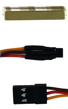
Connection of Bluetooth transmitter „LM-BT-S“:
The LM-BT-S has a cable with 2 plugs.
Connection to sound speed controller SFR-1:
• The plug with the single, orange cable is plugged into pin header X5/I. The
orange cable points towards the center of the board.
• The plug with the brown and red cable is responsible for the voltage supply of
the Bluetooth module (4 - 6 V). This connector can be plugged into any free
proportional input (X2/3 - X2/6) of the SFR-1 or a servo output (X5/1 - X5/I) of
the SFR-1. The brown cable points to the edge of the board. If there are no
free slots available on the SFR-1, the connector can also be plugged into a
free slot on the RC receiver. If there is no more space here, a Y servo cable
must be used.
Connection to sound modul USM-RC-2:
• The plug with the single, orange cable is plugged into pin header X9. The
orange cable points towards the gray termional clamp X1.
• The plug with the brown and red cable is responsible for the voltage supply of
the Bluetooth module (4 - 6 V). This connector can be plugged into any free
proportional input (X2/1 - X2/4) of the USM-RC-2 or a servo output (X8/1 –
X8/2) of the USM-RC-2. The brown cable points to the edge oft he board, or
at the servo soututs to the SD card. If there are no free slots available on the
USM-RC-2, the connector can also be plugged into a free slot on the RC
receiver. If there is no more space here, a Y servo cable must be used.
Connection of Bluetooth receiver:
The Bluetooth receiver is already soldered onto the circuit board of the LM-BT-16-4.
No further connection is necessary here.
21.05.2021 BEIER-Electronic 7GB Bluetooth Light Module LM-BT-16-4
Connection of outputs
The outputs 1 - 16 of the module are on the socket headers X3 and X4.
The ribbon cable supplied can be used to connect the outputs. For a simple
connection (without soldering) the connection terminals AKL-8 and AKL-8-W can
also be ordered from us in our shop.
Of course, other cables/plugs can also be connected to pin strips X3 and X4. A cable
cross-section of 0.14 mm² - 0.5 mm² should be used for the switching outputs.
The light module always switches the negative pole to the connected load for all
outputs. The negative pole of the load is connected to the output of the light module
(see connection diagram).
The common positive pole for outputs 1 - 8 and 9 -16 are the black and white cables
of the ribbon cable. It is also possible to connect the load directly to the positive
terminal of the battery.
Assignment of ribbon cable:
Output Ribbon cable (X3)
1 brown
2 red
3 orange
4 yellow
5 green
6 blue
7 purple
8 grey
positive pole white
positive pole black
Ausgang Ribbon cable (X4)
9 brown
10 red
11 orange
12 yellow
13 green
14 blue
15 purple
16 grey
positive pole white
positive pole black
8 BEIER-Electronic 21.05.2021GB Bluetooth Light Module LM-BT-16-4
The switched voltage at the outputs (at 100 % brightness) is always as high as the
supply voltage of the module.
If LEDs are connected, series resistors must always be used. It does not matter
whether the series resistors are connected to the plus or minus line. The correct
polarity is important for LEDs, otherwise they do not light up.
The required series resistors for the LEDs depend on the LED colors and the LED
current. For orientation, here is a table with series resistors for standard LEDs
(current approx. 15 mA) as a rough guide:
Supply voltage Series resistor
6V 270 Ohm
7,2 V 330 Ohm
8,4 V 470 Ohm
9,6 V 510 Ohm
12 V 680 Ohm
There are also LED series resistor calculators on the Internet (e.g.
www.leds.de/widerstandsrechner) with which the ideal resistance can be calculated
quickly and easily.
If relays or other inductive loads (e.g. motors) are connected to the switching
outputs, free-wheeling diodes (e.g. 1N4007) must be used.
Connection of servos
4 servos or speed controllers as well as other modules that are intended for direct
connection to a receiver (e.g. relay modules, rotating beacons, etc.) can be
connected to the pin headers X5/1 - X5/4.
The orange cable points upwards.
If a speed controller is connected that has a BEC, the red wire must be removed
from the servo plug and isolated! This is necessary because the LM-BT-16-4 has its
own BEC, which is connected to the connections of the servo outputs.
The current consumption of all connected servos / modules at X5/1 - X5/4 must not
exceed 1 A (short time 4 A)! Otherwise an external BEC is necessary.
Connection of motor
A motor for e.g. trailer supports, ramps or tipping functions can be connected to
terminal X2. It is important that the current consumption of the motor does not
exceed 2 A (short time 3 A).
21.05.2021 BEIER-Electronic 9GB Bluetooth Light Module LM-BT-16-4
Connection of switch for manual motor control
An optional switch LM-SW can be connected to pin strip X5/6,
with which the motor can be controlled manually. For example,
the trailer supports can be moved without remote control. The
speed of the motor in manual mode is set in the LM-Teacher.
Connection of data cable K-USB-2
The data cable K-USB-2 is connected to the pin header X5/7. The orange cable
points upwards.
The light module is not supplied with voltage via the data cable. If the data cable is to
be used, the LM-BT-16-4 must be supplied with voltage via the battery (as normal).
The data cable is used to transfer and read out the settings of the light module. The
diagnosis can be used to check functions and search for errors. The data cable is
also required for a firmware update.
Road train
A Bluetooth transmitter LM-BT-S can also be connected to pin header X5/7, which
then forwards the received Bluetooth signal 1: 1 to another light module. In this way,
a road train can be implemented with several trailers.
The LM-BT-S has a cable with 2 plugs:
• The plug with the single, orange cable is plugged into pin header X5/7. The
orange cable points upwards.
• The plug with the brown and red cable is responsible for the voltage supply of
the Bluetooth module (4 - 6 V). This connector can be plugged into any free
servo output (X5/1 - X5/4) of the LM-BT-16-4. The brown cable points down. If
there is no more space at the servo outputs, a Y servo cable must be used.
Simultaneous operation of the data cable and the Bluetooth transmitter at X5/7 is not
possible! However, it can be plugged between the data cable and the Bluetooth
transmitter diode at any time.
All light modules of the road train always receive the same light signals for the 16
switching outputs. The signals for the 4 servo outputs and the motor output are also
initially identical for all light modules. Using the functions “LM: Activate road train ID
1” - “LM: Activate road train ID 7” on the towing vehicle, however, the servo outputs
and the motor output can be controlled very specifically with just one light module.
The road train ID can be set in the LM-Teacher (see page 19)
10 BEIER-Electronic 21.05.2021GB Bluetooth Light Module LM-BT-16-4
If, for example, the "LM: Activate road train ID 2" function is switched on via the
towing vehicle, the commands for the servo outputs and the motor output only affect
the light module that has ID 2. With all other light modules, the servo outputs and
motor outputs remain in the last state.
If no ID is selected on the towing vehicle, the commands for the servos and the
motor output are always carried out by all light modules. This is always the initial
state after switching on.
Connecting and disconnecting Bluetooth
The connection and disconnection of the Bluetooth connection between the
Bluetooth transmitter in the towing vehicle (LM-BT-S) and the Bluetooth receiver on
the light module works largely automatically.
• If the light module LM-BT-16-4 is supplied with voltage, it tries to establish a
connection with a Bluetooth transmitter LM-BT-S.
• The first attempt is always to reestablish the connection with the LM-BT-S that
was paired last.
• If the last paired LM-BT-S is not nearby (or not switched on), the area is
searched for further LM-BT-S. A connection to a "different / new" LM-BT-S is
only established if it is in the immediate vicinity (max. 1 - 1.5 m) of the light
module. This is to prevent LM-BT-S that are further away from being
unintentionally pairing.
• If several towing vehicles with active LM-BT-S are found in the vicinity (max. 1
- 1.5 m) during the search, the connection is established to the LM-BT-S that
is closest to the light module.The first connection to a new / different LM-BT-S
takes about 10 seconds, but the connection to the last coupled LM-BT-S is
very quick (about 1 second).
If the light module is paired with an LM-BT-S, the red LED on the LM-BT-16-4 lights
up permanently.
Thanks to Bluetooth technology, the transmitter and receiver do not need visual
contact and the range is several meters. However, this can also be a disadvantage,
since the light module still controls its outputs, servos and the motor after the towing
vehicle has been uncoupled and has already been driven further away. There are
now 2 possibilities to "switch off" the light module:
1. Via the "LM: transmission off" function on the SFR-1, the data transmission to
the light module can be switched off.
Caution: The Bluetooth connection will still be maintained! In this way, the
towing vehicle cannot be paired with another light module or the light module
cannot be paired with another towing vehicle. To do this, an existing Bluetooth
connection must always be disconnected first.
21.05.2021 BEIER-Electronic 11GB Bluetooth Light Module LM-BT-16-4
2. The magnetic sensor LM-MS can optionally be connected
to pin header X5/5 and activated in the LM-Teacher (see
page 19). In this case, a Bluetooth connection is only
established if there is a magnet near the magnet sensor.
However, if there is no (longer) a magnet in the vicinity of
the sensor, the Bluetooth connection is disconnected and
another towing vehicle or trailer / semitrailer can be
connected via Bluetooth.
In the case of trailers, for example, the magnet is attached
below the fifth wheel and the magnetic sensor is mounted above the king pin.
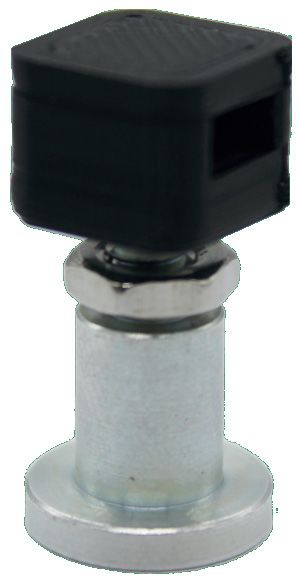
However, the king pin must be made of a material that conducts the magnetic
field lines well, for example steel or iron. King pins made of stainless steel or
aluminum are not suitable here. Here we offer the king pin KB-BT-T with
holder for the magnetic sensor.
However, the king pin must be made of a material that transmits the magnetic field
lines well, for example steel or iron. King bolts made of stainless steel or aluminum
are not suitable here.
For a simple and stable mounting we offer the king pin KB-BT-T with 3D
printed bracket suitable for Tamiya trucks. The sensor is inserted into the
recess and the bracket is screwed onto the king pin.
Switching outputs
The outputs are usually copies (forwarded signals) of the outputs of the module that
sends the IR signals to the LM-BT-16-4. This means that whenever an output is
activated on the SFR-1 or USM-RC-2, the output with the same number on the LM-
BT-16-4 also switches with the same intensity.
Example:
Output 4 is configured on the sound module as "indicator right". When the right turn
signal is switched on, output 4 on the sound module (indicator signal for the truck)
and output 4 on the light module (indicator signal for the trailer) at the same time.
12 BEIER-Electronic 21.05.2021GB Bluetooth Light Module LM-BT-16-4 The brightness of the output of both modules corresponds to the settings in the Sound-Teacher. Control via sound speed controller SFR-1: The outputs 1 - 16 of the LM-BT-16-4 are 1:1 copies of the outputs 1 - 16 of the SFR-1. Control via sound module USM-RC-2: The outputs 1 - 12 of the LM-BT-16-4 are 1:1 copies of the outputs 1 - 12 of the USM-RC-2. If servo outputs 1 and 2 are activated on the USM-RC-2, outputs 11 and 12 on the sound module cannot be used. However, these two outputs can still be used on the LM-BT-16-4. The outputs 13 - 16 can only be used for the special functions “all-round light”, “flashing light” and “running light”. 21.05.2021 BEIER-Electronic 13
GB                                                        Bluetooth Light Module LM-BT-16-4

Special light functions at outputs 13 - 16
The 4 outputs 13-16 have special light functions:
      • Rotating beacon (1x4-channel or 4x1-channel)
      • Indicator / flashing effects
      • Running light (4-channel)
The special light functions are permanently assigned to these outputs and cannot be
used for other outputs.

If the special light functions are to be used on outputs 13 - 16, these must be
activated in the LM-Teacher (see page 19).

There are different variants for the rotating beacon and the running light, which can
be set with the LM-Teacher software (see page 19).

The speed of the special light functions can also be set with the LM-Teacher.

1-channel rotating beacon (4 pieces)
This function simulates a rotating rotating beacon with one output. Of course, the
light cannot really rotate, so the effect is achieved by constantly increasing and
decreasing the brightness. This creates the impression of a rotating light (from the
distance).

There are in total 4 of the 1-channel rotating beacons at the outputs 13-16. The
speeds of the 4 rotating beacon are intentionally slightly different. So they are not
running in sync.

The speed of the 1-channel rotating beacon can be adjusted with the LM-Teacher.

4-channel rotating beacon (1 piece)
The 4-channel rotating beacon is an improved version of the 1-channel all-round
light. Here a rotating rotating beacon is simulated with 4 outputs. Of course, the 4
connected lamps/LEDs do not really rotate, but here too the effect is achieved by
increasing and decreasing the brightness of the 4 outputs.

The speed of the 4-channel rotating beacon can be adjusted with the LM-Teacher.

Flasher/indicators (4 pieces)
If the flasher are activated, the outputs 13 - 16 flash in different rhythms. These 4
outputs are always activated at the same time. A combination of these outputs can
create interesting effects (e.g. modern police flashing lights with 3 LEDs at outputs
13, 14 and 15).

 Output 13:      Short lightning pulse
 Output 14:      Short lightning double pulse
 Output 15:      Short double lightning pulse, slightly offset in time to output 14.
 Output 16:      Indicator

The speed of the flashers / blinkers can be set with the LM-Teacher

14                                   BEIER-Electronic                           21.05.2021
GB Bluetooth Light Module LM-BT-16-4 Running light (4-channel) A 4-channel running light can be generated via the 4 outputs 13 - 16. As an option it can be choosen whether the running light only runs in one direction or always back and forth (Knight Rider). The speed of the running light can be adjusted with the LM-Teacher Activation of special light functions The 4 special light functions can be activated via the free function assignment in the Sound-Teacher or Drive-Teacher, via the proportional channels, the Nautic mode, the EKMFA mode or the switching inputs. The functions are called in the Sound-Teacher: • LM: Rotating beacon • LM: Flasher • LM: Running light Controlling the servo outputs Four servos or speed controllers can be connected to the light module. All 4 servo outputs can be controlled separately from each other. In case of an interruption of the IR signal, it can be set whether the servos should move to neutral position (middle), or keep the last position. For each servo output, a basic position and two additional servo positions can be specified in the Sound-/Drive-Teacher. The speed of movement can also be set in the Sound-Teacher. The programmed positions can be activated via the free function assignment in the Sound-Teacher, via the proportional channels, the nautic mode, the EKMFA mode or the switching inputs. The functions are called: • LM: Servo 1 Position 1 • LM: Servo 1 Position 2 • LM: Servo 2 Position 1 • LM: Servo 2 Position 2 • LM: Servo 3 Position 1 • LM: Servo 3 Position 2 • LM: Servo 4 Position 1 • LM: Servo 4 Position 2 Direct, proportional servo control via a prop. channel is also possible. More information of the servo functions can be found in the operating manuals for the SFR-1 or USM-RC-2 modules. 21.05.2021 BEIER-Electronic 15
GB                                                         Bluetooth Light Module LM-BT-16-4

If, for example, the trailer supports are controlled via a speed controller, a
interference suppression of the IR receiver diode and the motor cables is important.
This can be done with ferrit rings (available in our shop).

Controlling the motor output
One motor can be connected directly to the light module (without an additional speed
controller).

The motor can be controlled with the functions "LM: Motor up" and "LM: Motor down"
with a fixed (but definable) speed.

Alternatively, the motor can also be controlled completely proportionally via a prop.
channel.

Optionally, the motor can also be controlled manually using a switch on pin strip
X5/6. The speed is set in the LM-Teacher. The standard speed is 40%. With a
supply voltage of 7.2 V, this corresponds to a motor voltage of approx. 3 V, which is
a suitable voltage for many trailer supports.

LEDs on LM-BT-16-4
The LEDs on the LM-BT-16-4 are indicating different states of the module:
           green LED                                   State
Steady light                  No Bluetooth connection
Flashing regularly            Bluetooth reception is ok
2 x flashing, then 3 s pause  Internal bluetooth receiver error
3 x flashing, then 3 s pause  Overcurrent at switching outputs
4 x flashing, then 3 s pause  Motor output overcurrent

           red LED                                         State
Steady light                     Bluetooth is paired
Flashing regularly               Bluetooth is not paired

16                                  BEIER-Electronic                             21.05.2021
GB Bluetooth Light Module LM-BT-16-4 PC software „LM-Teacher“ With the software "LM-Teacher" extended options of the light module can be configured. The software can be downloaded for free from our website. The light module is ready for operation in the delivery state. The use of this software is therefore not absolutely necessary! The data cable K-USB-2 and the LM-Teacher are only required if the extended settings are to be changed. System requirements • Windows compatible PC • Windows 2000, NT, XP, Vista, Windows 7, Windows 8 or Windows 10 • approx. 5 MB of free HD space • free USB port (1.0, 1.1, 2.0 or 3.0) Software installation After downloading the software, it must be installed on the PC. To do this, start the downloaded file and simply follow the instructions of the installation program. To start the program easily create a desktop icon. 21.05.2021 BEIER-Electronic 17
GB                                                     Bluetooth Light Module LM-BT-16-4

Using software „LM-Teacher“
Menue

             Create new project             Creates a new project
             Open project                   Opens an existing project
             Save project                   Saves the current project
             Save project as                Saves a copy of the current project with
     File                                   a new name
             Check automatically for        When starting the LM-Teacher, it will be
             updates                        checked if a new version is available
             Check now manually for         Checks if a new version is available
             updates
             Close                          Exit the LM-Teacher
             Upload configuration to        Transfer of all LM-Teacher settings to
             light module                   light module
Data cable
             Download configuration         Download of all settings from light
             of light module                module to LM-Teacher
             German                         Switches to German language
             English                        Switches to English language
Language
             French                         Switches to French language
             Dutch                          Switches to Dutch language
             Operating manual               Opens this manual (PDF)
     Help
             Info                           Shows informations about the software

Functions

There are three areas in the LM-Teacher:
   • Configuration
   • Diagnosis
   • Firmware update

18                                BEIER-Electronic                           21.05.2021
GB Bluetooth Light Module LM-BT-16-4 Configuration – Light module The settings in the picture show to the delivery status. General An ID from 1 to 7 can be assigned to each light module. With a road train, the servo outputs and the motor output can be controlled with just one module using this ID. If no road train is implemented, the ID is irrelevant. Here you can set whether a magnetic sensor should be used for connecting and disconnecting Bluetooth (see page 10). If no magnetic sensor is connected, this option must not be activated, otherwise no connection to the towing vehicle will be established! Servo outputs In case there is no IR connection you can choose in this box whether the servo outputs should move to neutral position (center) or hold their last position. Engine output If the motor output is controlled via the manual switch at X5/6, the speed can be set here. 100% corresponds to the maximum speed (voltage for motor = supply voltage of the LM-BT-16-4). If the motor should run more slowly, the speed can be reduced here. For a voltage of approx. 3 V at the motor, a speed of approx. 40% is required with a 7.2 V battery. 21.05.2021 BEIER-Electronic 19
GB                                                        Bluetooth Light Module LM-BT-16-4

All-round / flashing / running lights (Outputs 13 – 16)
If outputs 13 - 16 are to be used for the special light functions, this must be activated
here.

There are two options for the all-round light, either 4 x 1-channel or 1 x 4-channel.

For the running light you can choose between a normal (runs in one direction only)
and a Knight Rider running light (runs back and forth).

The speed for all three special lights can be adjusted in 10 steps.

Diagnosis

A diagnostic function is integrated in the LM-Teacher. This feature is very helpful to
check the various functions of the light module. The data cable
K-USB-2 must be connected to X5/7 at the light module.

The diagnosis window is divided into different areas: servo outputs, motor,
miscellaneous, outputs, inputs and data.

The following explains what is displayed in the different areas:

Servo outputs
The current positions of the 4 servo outputs are displayed here.

20                                   BEIER-Electronic                           21.05.2021
GB                                                          Bluetooth Light Module LM-BT-16-4

Engine
Some values of the motor output stage are displayed in this area. These are mainly
used for internal testing purposes.

Miscellaneous
The values displayed here are primarily for internal testing.

Outputs
The 16 switching outputs of the light module are displayed here. If an output is
switched on, this is marked by a green circle.

If "test" is activated, all 16 outputs are briefly switched on as a running light. With
this, e.g. the wiring of the outputs can be tested (on the fly) without a transmitter.

Inputs
The inputs for manual motor operation and the input of the magnetic sensor are
shown here.

Data
The values displayed here are mainly intended for internal testing purposes.

Diagnostic recording
A diagnosis can be recorded in a file on the hard disk. The light module must always
be connected with the data cable during recording.

21.05.2021                            BEIER-Electronic                                    21
GB                                                     Bluetooth Light Module LM-BT-16-4

Firmware update

The right firmware for the light module is always integrated in the LM-Teacher. If
there is an update for the LM-Teacher, a new firmware for the light module is always
loaded.

The firmware update can either be started manually or the LM-Teacher receives an
automatic notification as soon as new firmware is available.

The update takes about 6 seconds. The green LED flickers during the update
process.

Never disconnect the module from power supply while updating!

22                                 BEIER-Electronic                          21.05.2021
You can also read