Payload: Instrument Control Unit - IL CONTRIBUTO ITALIANO ALLA MISSIONE PLATO - Inaf
←
→
Page content transcription
If your browser does not render page correctly, please read the page content below
Rosario Cosentino
FGG-INAF
cosentino@tng.iac.es

Payload: Instrument Control Unit
IL CONTRIBUTO ITALIANO ALLA MISSIONE PLATO
Palermo 2-3 Maggio 2011

On behalf and with extensive inputs from the ICU Team:
INAF (Italy): Rosario Cosentino, Anna Maria Di Giorgio, Stefano Pezzuto,
University of Florence (Italy): Mauro Focardi, Maurizio Pancrazzi, Emanuele Pace
University of Vien (Austria): Franz Kerschbaum, Roland Ottensamer.
ICU
R. Cosentino (FGG)
Subsystem
Subsystem Engineering
Management
E. Pace (Uni. Firenze)
R. Cosentino (INAFFGG)
ICU Hardware ICU Software
M. Focardi (Uni Firenze) S. Pezzuto (INAFIFSI)
Electronics Data Compression
Application
Housing
Software
Interface
Il contributo italiano alla missione PLATO -Palermo 2-3 Maggio 2011
Il contributo italiano alla missione PLATO -Palermo 2-3 Maggio 2011

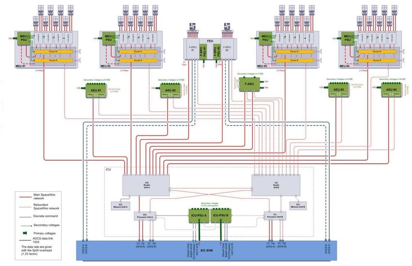
Overview
MEUs F
(4 NDPU) DPUs
AEUs FAEU
● 4 MEU (the 16 normal DPU are
gathered in 4 group of 4 DPUs)
● 2 Fast DPU
Memory and IO Unit
● 4 Ancillary Electronic Unit
Memory Unit ICU ● 1 Fast Ancillary Electronic Unit
● 1 MEU-PSU
Processor Unit Power
Supply Unit
Each unit include 2 router (main
SpW interface to SVM and redundant)
S/C SVM
Il contributo italiano alla missione PLATO -Palermo 2-3 Maggio 2011
Overview
● Handle the communications with spacecraft
MEUs ● Receive and process telecommands for the ICU:
F
(4 NDPU) DPUs the received commands shall be validated prior to
their execution
● Format and transmit cyclic and sporadic HK
AEUs FAEU telemetry (HKTM)
● Format and trasmit the scientific payload
telemetry packets (PLTM)
● Manage the SpaceWire network
• Receive the onboard time (Central Time
Memory and IO Unit
Reference) from the S/C, handle the time
stamping of the data transmitted in HKTM and
Memory Unit ICU forward the CTR to the DPUs.
• Produce state and diagnosis information (cyclic
Processor Unit Power status, progress event).
Supply Unit • receive the spacecraft time code from the S/C
and forward it to the DPUs
SpW interface to SVM • Schedule the DPU tasks (by the way of
commands sent to the DPUs)
• Manage the data flow
S/C SVM • Manage the mode transitions
• Manage the Software parameters
• Manage the maintenance of the ICU software
• Manage the maintenance of the DPU software
Functional characteristics (observation and configuration
mode)
Network architecture and management (SpaceWire)
Data volume and TM budget
Hardware architecture
ICU: new design
PROCESSOR Module
MEM & I/O Board
MOTHERBOARD
ICU mechanical assembly
ICU Budget (mass and power)
SW structure
Model philosophy
Objective of the definition phase
ICU Development Plan
Il contributo italiano alla missione PLATO -Palermo 2-3 Maggio 2011
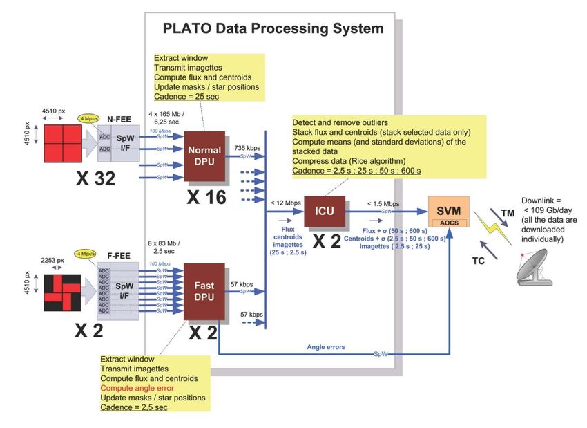
receive the flux, the centroids and the imagettes (F-DPU: every
2.5 s ; N-DPU: every 25 s);
compress the imagettes: a compression factor 2 and 3 is
guaranteed;
detect outliers (flux and centroid) by comparing the data
corresponding to the same star and coming from N-groups
telescopes (N=8 or N=16 or N=32);
stack the valid flux and centroids;
compute the mean and the std dev of the stacked
measurements at a cadence depending of the sample category
(50 sec. or 600 sec): F-DPU: K ≤ 20; N-DPU: K ≤ 2 (50 s) or K ≤
24 (600 s);
bufferize and compress photometric and centroid data: a factor
of ~ 2 is guaranteed;
format and transmit to the SVM the scientific packets (PLTM).
Il contributo italiano alla missione PLATO -Palermo 2-3 Maggio 2011
Send the star catalogue and other configuration parameters to DPU
Cross check between data from telescopes of the same LoS (verify the
consistency of the list and positions of all the stars).
Schedule the DPU tasks
Compress full-frames images from DPUs
Packetization and trasmission to SVM of all the data sent by DPU which
allow to valid on-ground operation:
Far field’ full images
List of background window position and background intensities
Parameters for candidate and reference stars
List and position of reference stars
Distortion matrix
Selected parameters of all the targets (position, mask, …)
No storage of data (only temporary buffering)
periodically or loss of the Los
Il contributo italiano alla missione PLATO -Palermo 2-3 Maggio 2011 The active ICU is responsible for managing the SpaceWire
network: ICU is a remote network manager.
The active ICU configures the routers (routing table, link speed,
etc.): the logical addressing will be used (no path addressing).
The active ICU manages (configures / monitors/ controls) its own
routers and the MEU routers.
Il contributo italiano alla missione PLATO -Palermo 2-3 Maggio 2011 32 normal telescopes + 2 fast telescope 4 detectors each telescope (4510X4510 CCDs) Data volume = 212 Gb/day (imagettes, photometric data, centroid data, raw images) Presently the TM rate is 106 Gb/day ICU shall compress data by a factor 2 at least ICU shall manage an input datarate from NDPU and FDPU of about 12 Mbps and an output datarate to the SVM of about 1.5 Mbps. These data rates can be easily managed by the standard SpW link, running up to 100 Mbps. Il contributo italiano alla missione PLATO -Palermo 2-3 Maggio 2011
Constraint:
     o Storing large amount of data (to achieve a compression
       factor of 2)
     o Handle a large number of SpW links

     Proposed Hardware characteristics:
     o a routing unit for an efficient management of the SpW
       network and a wide internetworking capabilities,
       implementing two or three routers
     o a processor unit (i.e. a motherboard with power processing
       capabilities)
     o a memory unit for data storage and buffering with one or
       more SpW links to manage and configure them
     o a power supply unit with redundancy.

Il contributo italiano alla missione PLATO -Palermo 2-3 Maggio 2011
ICU box EIDB constraints:
constraints
Volume: 250 x 240 x 220 mm3,
Mass: 6.8 Kg
3 “stacked” Units:
Processor Unit
Memory & I/O Board
Power Supply Unit
Back panel (or mother board)
for signals routing and cross
strapping
Il contributo italiano alla missione PLATO -Palermo 2-3 Maggio 2011C&C_A _N EG S EC & C _ A _ R 28V
O n /O f f P r im a r y P o w e r
HPC Bus
R 4_ A
A T7910
P r o c e s s o r S u p p ly
B o ard A
Contribution from Thales Alenia
C o n d itio n in g
C &C and TC &TM
M UX
ADC
FPG A
A
M o n ito r in g S e c o n d a r y V o lta g e s A
BootPRO M N O R F la s h E E P R O M
6 4 M B y te
Space Italy:
1 2 8 K B y te
( 4 x 3 2 K x8 ) ( 2 x 1 6 M x1 6 c u b e s )
LEO N2
CPU_A
8 M B yte x IC U
A T697F 8 M B yte x D P U s
SRA M 3 2 M B yte x S ta r C a ta lo g u e
8 M B y te + E d a c 1 6 M B yte S p a r e
( 5 x 2 M x8 c u b e s )
P ro c es s o r B o ard A
IN _ 1 _ A
R1_A
IN _2_ A
M E M & IO B o a r d A
IN _3_ A
IN _4_ A
S pW
11 SpW links
IN _5_ A
I/F
IN _6_ A
A T7910
W R _ C tr l
FP G A
M E M _ C tr l
FPG A
R D _ C tr l
FP G A
A A A
IN _7_A
R2_A
IN _8_A S pW
IN _9_A I/F
2 PSU (M + R);
IN _10_A
IN _11_A
A T7910
8 G b it S D R A M
(2 5 6 M x 3 2 )
[( 4 + 2 ) x 2 G b it C u b e s ]
P L A T O IC U
2 discrete command lines and a main power
line (28V) from SVM to ICUPSU A/B.
IN _ 1 _ B 8 G b it S D R A M
R1_B (2 56 M x 32 )
IN _2_ B [( 4 + 2 ) x 2 G b it C u b e s ]
IN _3_ B
IN _4_ B
IN _5_ B S pW
I/F
IN _6_ B
A T7910
W R _ C tr l M E M _ C tr l R D _ C tr l
FP G A FPG A FP G A
B B B
IN _7_B
R2_B
IN _8_B
S pW
IN _9_B I/F
IN _10_B
IN _11_B
M E M & IO B o a r d B
A T7910
P ro c es s o r B o ard B
SRA M N O R F la s h E E P R O M
8 M B y te + E d a c 6 4 M B y te
( 5 x 2 M x8 c u b e s ) ( 2 x 1 6 M x1 6 c u b e s )
LEO N2
CPU_B 8 M B yte x IC U
BootPRO M A T697F 8 M B yte x D P U s
3 2 M B yte x S ta r C a ta lo g u e
1 2 8 K B y te 1 6 M B yte S p a r e
( 4 x 3 2 K x8 )
S e c o n d a r y V o lta g e s B
C o n d itio n in g
C &C and TC &TM
M UX
ADC
FPG A
B
M o n ito r in g
P r o c e s s o r S u p p ly
B o ard B
A T7910
R 4_ B
O n /O f f 28V
HPC P r im a r y P o w e r
C&C_A _N EG S E C&C_A _R Bus
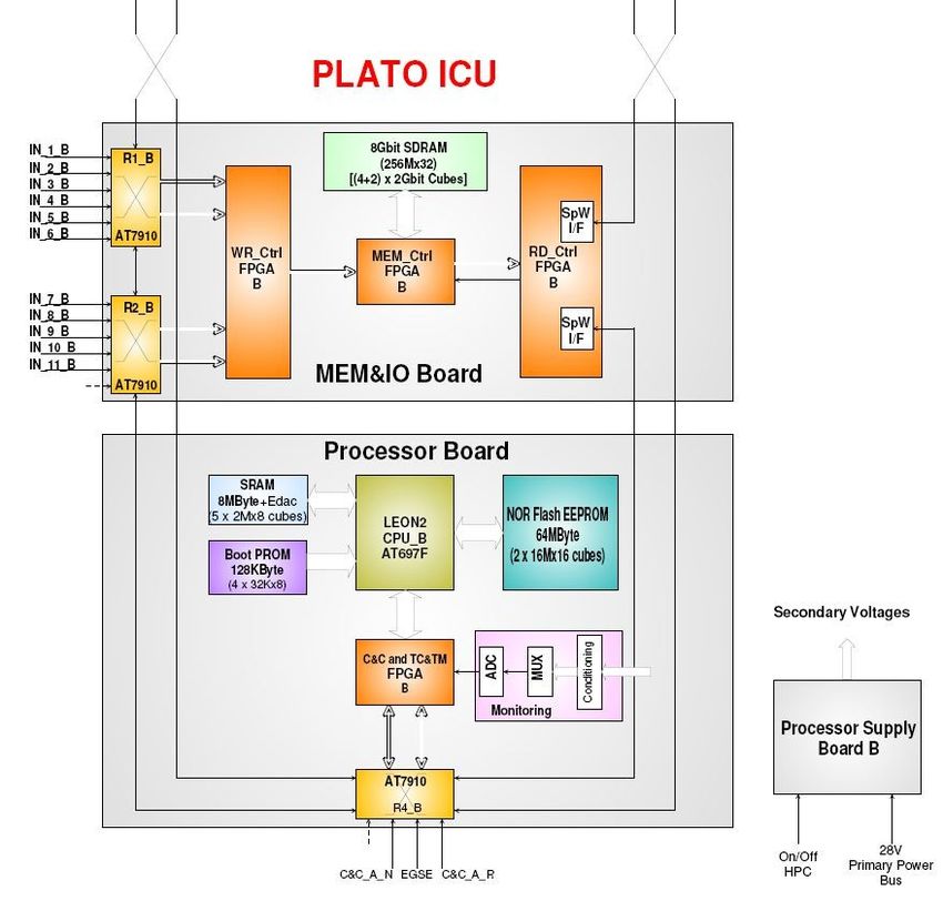
Il contributo italiano alla missione PLATO -Palermo 2-3 Maggio 2011 The Processor Module board is built around a LEON 2 (AT697F) radiation tolerant
single chip microprocessor based on SPARC V8 architecture.
Microprocessor includes on chip an Integer Unit (IU), a Floating Point Unit (FPU), a
Memory Controller and a DMA Arbiter.
Fault tolerance is supported using parity on internal/external buses and EDAC on the
external data bus.
Several Processor Modules could be implemented for a homogeneous or
heterogeneous multiprocessor systems with multitasking capabilities thanks to RTEMS
OS, in order to appropriately process and compress digital data.
Il contributo italiano alla missione PLATO -Palermo 2-3 Maggio 2011 128 KByte Boot PROM is provided for the bootstrap & initialization SW.
64 MByte NOR Flash (2X16Mx16 cubes) is provided to store on board the ICU and N
DPU Application SW and star catalogue. The memory can be fully patched and dumped
during flight by means of telecommands.
8 MByte SRAM (2Mx32 with EDAC) is provided for Application SW execution.
Both FLASH and SRAM are protected by the processor EDAC correcting any single bit
error and signaling any double bit error detected.
FLASH memory can be switched off when not accessed for long time in order to improve
their data retention performance and to minimise consumption. The FLASH On/Off switch
is commanded through a GPIO line of the Processor.
Il contributo italiano alla missione PLATO -Palermo 2-3 Maggio 2011The Processor Module host a 8x SpaceWire Router ASIC (ATMEL AT7910E) as baseline. Up to 4 SpW links are accessible from outside whilst the remaining 4 SpW links are used for connection and cross strapping with other modules internal to the unit. The SpW Router ASIC acts also as network terminal node thanks to the two 8 bit wide parallel ports it provides. 4 external SpW links could be used for both Command & Control purposes and/or for transfer of low/medium data rate packets from/to SpW sources (e.g. the satellite central on board computer). A SpW link is foreseen for EGSE pourposes. The Router interfaces an ACTEL RTAX2000S FPGA responsible for communication and control procedures, for clock division and distribution and for OnBoard reference Time production and syncronization (by means of Timecode SpW packets from OBC). Il contributo italiano alla missione PLATO -Palermo 2-3 Maggio 2011
The Memory Module (MM) is based on SDRAM memories and it can be powered on/off and
   controlled by the Supervisor module (M or R). Req’s are 8Gb.
   It consists of three main blocks:

   ⇒ Power Distribution and On/Off circuitry;
   ⇒ The Memory Controller FPGA (ACTEL RTAX2000S);
   ⇒ The SDRAM Memory Array;

   The Processor Module handles all the digital I/Fs of the MM and all the operations on the
   memory array: initialisation, writing, reading, refresh, scrubbing and the local redundancy
   management.

Il contributo italiano alla missione PLATO -Palermo 2-3 Maggio 2011
The I/O module consist of the following blocks:

       ⇒2 SpW routers in charge of the SpW I/F with the PLATO DPS, Nom/Red Supervisor
       module and with the SpW router to the SVM;
       ⇒The Input WRC FPGA and the Output RDC FPGA in charge of managing data packets
       writing on or reading from the MM;
       ⇒Power Distribution and On/Off circuitry;

       The SpW router ASIC receives SpW packets from PLATO DPS via 6+5 SpW links and
       routes them via its two parallel output ports to the WRC FPGA, which stores them into the
       Memory Array throungh the MEMC FPGA.

       The RDC FPGA retrieves TM packets allocated inside the Memory Array, formats and
       forward them to the SpW I/F included in the RDC FPGA.

       The operations of the SpW routers on the I/O Module can be configured, controlled,
       monitored by the operational Processor Module via SpW I/F (e.g. routing table
       programming for logical addressing, speed selection…etc).

Il contributo italiano alla missione PLATO -Palermo 2-3 Maggio 2011
The Motherboard is the mean through which the Nominal and Redundant Daughterboards are connected and exchange the power and signal lines each other. Thanks to the use of a motherboard PCB there are no wire connections inside the unit. All the I/O connectors are directly mounted on the relevant PCB modules. The Motherboard is equipped with straight connectors and lies on the ICU bottom panel while the Daughterboards are inserted through the top of the unit and plug into the Motherboard through rightangle connectors. All the Modules are implemented on “extended” double Eurocard PCBs (200 mm x 233 mm). Mass 300 g. Il contributo italiano alla missione PLATO -Palermo 2-3 Maggio 2011
The ICU is composed by N nominal + N redundant daughterboard modules perpendicularly plugged onto a motherboard that lays on the unit bottom. The motherboard is fixed by screws to the unit bottom plate. Each daughterboard is provided with motherboard connectors on one of the 233mm side and with the external I/O connectors on the opposite side. The daughterboards are stiffened by a mechanical frame on which the external I/O connector are fixed and that are screwed to the unit upper panels. The lateral sides of the modules are equipped with cardlock retainers that are used to fix the boards to the unit lateral panels. Il contributo italiano alla missione PLATO -Palermo 2-3 Maggio 2011
mar11 n. Brd
Mass [g] T. Mass [g]
Box 2000 1 2000
Power Supply Module 1150 2 2300
Processor Module 600 2 1200
February 2011 TC/TM 700 2 1400
I/O module 500 2 1000
64 Gbit 350 2 700
motherboard 250 1 250
Tot. 8850
apr11 n. Brd
Mass [g] T. Mass [g]
Box 1700 1 1700
1100 2 2200
Power Supply Module
550 2 1100
April 2011 Processor Module
600 2 1200
Memory & I/O Module
300 1 300
Motherboard
Tot. 6500
2350 g less
Il contributo italiano alla missione PLATO -Palermo 2-3 Maggio 2011Dimensions
The dimension of a (manufactured) unit composed of:
• 2 Power Supply modules (1N+1R)
• 2 Processor modules (1N+1R)
• 2 Memory & Input/Output modules (1N+1R)
are:
⇒ 260 x 250 x 251 mm [L x W x H] not considering the mounting feet
⇒ 260 x 278 x 251 mm [L x W x H] including the mounting feet
In March the dimension was:
⇒ 340 x 253 x 251 mm [L x W x H] not considering the mounting feet
⇒ 340 x 278 x 251 mm [L x W x H] including the mounting feet
This data is NOT fully compliant but very close to the PLATO ICU dimensions reported in
the EIDB document and in the URD (220 mm x 250 mm x 240 mm).
Il contributo italiano alla missione PLATO -Palermo 2-3 Maggio 2011The ICU (Main + Redundant) overall power budgeis 19.8 W x 2 maximum
Max power consumption [W] global mass [g]
Power Supply Module 2.9W 85% min efficiency
Processor Module 6.1W
I/O & Memory Module 10.8W 8Gbit
Motherboard
total max primary
power consumption 19.8W
Il contributo italiano alla missione PLATO -Palermo 2-3 Maggio 2011There are 4 kinds of SW available to the ICU:
Bootstrap SW (BSW)
Operating system (OS)
Drivers
Application SW (ASW)
BSW and drivers provided by the ICU HW
manufacturer;
OS depends on the adopted microprocessor; real
time OS commercially available, like RTEMS.
Drivers will be developed such that they will be
integrated in the OS.
The ASW is under responsibility of IFSI-INAF.
The code shall be written in C; some module may
be required to be written in Assembly.
Il contributo italiano alla missione PLATO -Palermo 2-3 Maggio 2011Il contributo italiano alla missione PLATO -Palermo 2-3 Maggio 2011
PLATO Payload development is based on
tests on Qualification Models (QM)
Acceptance tests on a Flight models (FM).
Models sequentially built and tested:
Breadboards or EBBs see later (industrial plan)
Structural and Thermal Model (STM)
Engineering Models (EM) (2 models)
Qualification Model (QM)
Flight Model (FM)
Spare Model
Il contributo italiano alla missione PLATO -Palermo 2-3 Maggio 2011 ICU architecture
Detailed architecture
Software design
▪ Software Requirement Specification
▪ Software Interface Control Document
▪ Interface document
Docs
Draft at the DPS meeting on January 2011
Final release on April 2011
October 2011 selection
December 2011 PDR
Il contributo italiano alla missione PLATO -Palermo 2-3 Maggio 2011Activities/Milestones Start End remarks
ICU PreDefinition Phase Nov. ‘10 Jan. ‘11
Specification Freezing Architecture Detailed
ICU Definition Phase Feb. ‘11 Apr. ‘11
Definition
ICU Implementation Phase KickOff T0 01 Oct. ‘11
ICU Detailed Design Oct. ‘11 Dec. ‘11 Detailed Design Documentation & Analysis
Preliminary Design Review (PDR) T0 + 3 02 Jan. ‘12
Electrical, Mechanical and Software
Jan. ‘12 Mar. ‘12∗
Detailed Design
ICU STM MAIT Apr. ’13 Jun. ‘13 Structural & Thermal Model
EM partially completed, delivered temporally
to ESA and returned to industry at the
ICU Bread Boarding Apr. ‘12 Jun. ‘12∗ completion of the test. The test procedures
had to be defined and communicated to
ICUTEAM as soon as possible.Activities/Milestones Start End remarks
2 deliverable units, internally not redounded,
ICU EM MAIT Apr. ‘12 Dic. ‘12 based on extended temperature range EEE parts,
Fit & Form compatible with FM
Critical Design Review (CDR) T0 + 12 Oct. ‘12
1 deliverable unit fully equipped, internally
redounded, based on extended temperature
ICU QM MAIT Oct ‘12 June. ‘13 range EEE parts, same type and same
manufacturer of FM, Fit, Form & Function
compatible with FM.
Qualification Review (QR) T0 + 21 July ‘13
1 deliverable unit fully equipped, internally
redounded,
ICU FM MAIT July ‘13 Apr. ‘14 based on QMLQ EEE parts (t.b.c. according to
PA Plan), or higher level in case the reliability goal
is not met with QMLQ.
Acceptance Review (AR) T0 + 30 Apr. ‘14
1 board per type (or a set of EEE Parts to
ICU Spare Set July ‘13 Mar. ‘14
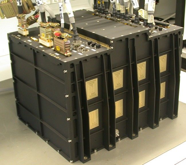
manufacture a board per type)ICU mechanical assembly All panels are made of surfacetreated aluminium alloy (Alodine) and externally painted in black (except Bottom panel) to improve radiating exchange with the environment. The thickness of the panels is designed to cope with the heat dissipation needs; in particular the thickness of the lateral panels increases from top to bottom to facilitate the heat sink.
You can also read