USER'S MANUAL Compact Laser Displacement Sensor HL-G1 Series (Console-dedicated Version)
←
→
Page content transcription
If your browser does not render page correctly, please read the page content below
USER'S MANUAL

  Compact Laser Displacement Sensor
HL-G1 Series (Console-dedicated Version)

                             ME-HLG1DP(00) No.0014-99V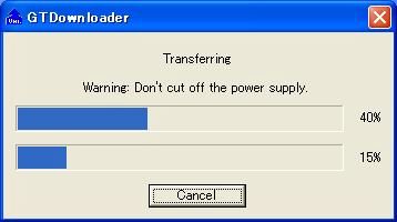
HL-G1 Series User’s Manual (Console-dedicated Version)
Introduction
Thank you for downloading the "Screen Data for GT-series Programmable Display for
the HL-G1-series Compact Laser Displacement Sensor." Read this manual carefully
and be sure you understand the information provided before attempting to install and
operate the product so that the product will fully demonstrate its superior performance.
Refer to the website of Panasonic Electric Works SUNX Co., Ltd.
(http://panasonic-electric-works.net/sunx) for the latest information on the product as
well as the latest version of the manual.
Note
1. The illustrations of the product in the manual may differ from the actual design of the
product.
2. The contents of this user's manual may change without notice for possible improvements
in the future.
3. All rights reserved. No part of this publication may be reproduced, stored in a retrieval
system, or transmitted, in any form, or by any means, mechanical, electronic,
photocopying, recording, or otherwise, without the prior written permission of Panasonic
Electric Works SUNX Co., Ltd.
4. The utmost attention has been paid to the creation of this manual. Should you find any
errors, omissions or inaccuracies, contact the nearest office of Panasonic Electric Works
SUNX Co., Ltd.
5. Panasonic Electric Works SUNX Co., Ltd. shall be in no case responsible for any
consequences resulting from your operation of the product.
Conventions
The following conventions are used to indicate and classify precautions in this manual.
Always heed the information provided with them.
Indicates information that, if not heeded, is likely to result in
loss of life or serious injury.
Indicates information that, if not heeded, could result in
relatively serious or minor injury, damage to the product, or
faulty operation.
Explains matters that should be observed or mistakes that
the user is apt to make.
Explains items that should be kept in mind, relevant
information in detail, and references.
0HL-G1 Series User’s Manual (Console-dedicated Version)
Table of Contents
Introduction .......................................................................................................... 0
Table of Contents.................................................................................................................1
1. Introduction of HL-G1 Dedicated Console ........................................................ 2
1-1 Applicable Programmable Display Models .....................................................................2
1-2 Steps to Introduce Dedicated Console ...........................................................................3
2. Nomenclature ................................................................................................... 4
3. Acquiring and Writing Screen Data................................................................... 5
3-1 Use Condition.................................................................................................................5
3-2 Downloading Dedicated Software ..................................................................................7
3-3 Installing USB Driver ......................................................................................................8
3-4 Writing Screen Data .......................................................................................................9
4. Sensor Connections and Initial Settings ......................................................... 10
4-1 Mounting Console ........................................................................................................10
4-2 Connecting Dedicated Console to HL-G1 .................................................................... 11
4-3 HL-G1 Settings.............................................................................................................13
4-4 Changing and Saving Display Language of Console...............................................................14
5. Screen Configuration and Basic Operation .................................................... 15
5-1 Top Menu Screen and Basic Buttons ...........................................................................15
5-2 Basic Console Operation..............................................................................................16
5-3 Console-dedicated Functions.......................................................................................19
6. Screen Transition Charts ................................................................................ 21
6-1 GT02 Screen Transition ...............................................................................................21
6-2 GT12 Screen Transition ...............................................................................................24
1HL-G1 Series User’s Manual (Console-dedicated Version)
1. Introduction of HL-G1 Dedicated Console
1-1 Applicable Programmable Display Models
Panasonic Electric Works SUNX's GT-series Programmable Display (any of the
following models sold separately) can be used as a dedicated console by connecting
the Programmable Display to the high-functional model (HL-G1□□-S-J) of the
HL-G1 Compact Laser Displacement Sensor and writing dedicated screen data to
the Programmable Display.
The dedicated console makes it possible to make sensor head settings and monitor
measurement values remotely.
GT-series Programmable Display models applicable
Applicable series names ··················· GT02 or GT12 Series
Power supply voltage ······················· 24 VDC
Communications port ······················ RS-422 (RS-485)
SD card memory slot ······················· None (or not used)
Products applicable
No. of connection Product
Screen Backlight Body color Product no.
units name
GT02G 3.8-inch Green/Orange/Red Pure black AIG02GQ14D
Single STN
connection GT02M 240 x 96 White /Pink/ Red Silver AIG02MQ15D
dots
Pure black AIG12GQ14D
GT12G 4.6-inch Green/Orange/Red
Multi connection STN Hairline silver AIG12GQ15D
(1 to 4 units) 320 x 120 Pure black AIG12MQ14D
GT12M dots White /Pink/ Red
Hairline silver AIG12MQ15D
GT02 Series measurement GT12 Series measurement value display
value display (with four HL-G1 units connected)
• The GT02□ Series controls a single sensor head over RS-422.
• The GT12□ Series controls a maximum of four sensor heads over RS-485.
For information on the installation and connection of the GT Series, download the
GT-series User's Manual. Read the manual carefully and be sure you understand the
information provided before attempting to install and operate the GT Series.
2HL-G1 Series User’s Manual (Console-dedicated Version)
1-2 Steps to Introduce Dedicated Console
This section provides brief information on the introduction of the GT Series as a
dedicated console.
For the procedure in detail, refer to "3. Acquiring and Writing Screen Data”.
● Preparation
• PC connected to the Internet
* For the operating environment of the PC, refer to "GT-series User's Manual"
(p. 1-9).
• USB cable (for A-to-mini B-connector connection)
• Power supply for Programmable Display (24 VDC)
● Writing HL-G1-dedicated screen data to the GT-series
Acquiring and writing screen data
[1] Downloading dedicated software
[2] Writing screen data to the GT Series
● Using GT Series as HL-G1-dedicated console.
Connecting the console to the sensor head and making initial settings
[1] Installation
[2] Connecting the dedicated console to the HL-G1
[3] Making HL-G1 settings
[4] Changing and saving the display language of the console
Console operation
[1] Basic operation
[2] Console-dedicated function
[3] Setting of each function and measurement value display (list of screen
transition)
For each function of the sensor head, refer to the "HL-G1-series User's Manual”.
3HL-G1 Series User’s Manual (Console-dedicated Version)
2. Nomenclature
GT02 Series
Side view Front view Side view Rear view Operation mode
setting switch
COM. Port Battery cover Battery holder
USB connector
(mini B)
Operation mode setting switch
SW No. Function OFF ON
ON
1 Reserved (not used) Always turned OFF
OFF Not allowed to go to Movement Movement
2 system menu possible prohibited
1 2 3 4
MODE 3
Reserved (not used) Always turned OFF
4
GT12 Series
Side view Front view Side view Rear view Operation mode
setting switch
SD card COM. Port Battery cover Battery holder
memory slot
USB connector
(mini B)
Operation mode setting switch
SW No. Function OFF ON
ON
1 Reserved (not used) Always turned OFF
OFF Not allowed to go to Movement Movement
1 2 3 4
2 system menu possible prohibited
MODE 3
Reserved (not used) Always turned OFF
4
The SD memory card slot or internal battery is not used in the case of using either one of the
above as a dedicated console for the HL-G1 Series.
4HL-G1 Series User’s Manual (Console-dedicated Version)
3. Acquiring and Writing Screen Data
3-1 Use Condition
PEWJSX(E_Software_LicenseB)101001
Software License Agreement
Panasonic Electric Works SUNX Co., Ltd. (“PEWJSX”) grants to you a license to
use this Software on condition that you accept this Agreement. You must read this
Agreement carefully before using this Software. Only in case that you accept this
Agreement, you may start your use of this Software.
Your unsealing the package of this Software, or your downloading, installing or
launching this Software or likes shall be deemed as your acceptance of this
Agreement.
Article 1 Grant of License
PEWJSX hereby grants to you a non-exclusive license to use this Software
only in combination with PEWJSX product(s) specified in the manual of this
Software in accordance with the terms of this Agreement. You may not use
this Software in connection with products of any third party other than
PEWJSX.
Article 2 Restrictions
You may NOT:
(1) Modify, reverse engineer, decompile, or disassemble this Software,
(2) Distribute, rent, lease or otherwise transfer this Software, and
(3) Use this Software by methods or for purposes other than those
specified in the manual of this Software provided by PEWJSX.
Article 3 Disclaimer
3-1. PEWJSX HEREBY DISCLAIMS ALL OTHER WARRANTIES ON THIS
SOFTWARE, EITHER EXPRESS OR IMPLIED, INCLUDING BUT NOT
LIMITED TO THE IMPLIED WARRANTIES OF MARCHANTABILITY,
FITNESS FOR PARTICULAR PURPOSE, AND NON-INFRINGEMENT
OF THIRD PARTY RIGHTS.
3-2. UNDER NO CIRCUMSTANCES SHALL PEWJSX BE LIABLE FOR ANY
DAMAGES (INCLUDING DIRECT, INDIRECT, INCIDENTAL,
CONSEQUENTIAL OR SPECIAL OR WHATSOEVER) ARISING OUT
OF THE USE OF THIS SOFTWARE, INABILITY TO USE THIS
SOFTWARE, DEFECTS IN THIS SOFTWARE (e.g., BUGS, SECURITY
HOLES, AND MALFUNCTION), OR OTHERWISE IN CONNECTION
WITH THIS SOFTWARE.
5HL-G1 Series User’s Manual (Console-dedicated Version)
Article 4 Term
4-1. This Agreement shall come into effect upon your unsealing the package of
this Software, or your downloading, installing or launching the Software or
likes.
4-2. PEWJSX may terminate this Agreement immediately, if you breach any of
the provisions of this Agreement.
4-3. You shall, at your own costs, return, delete or destroy this Software and
any of its copies within four (4) weeks after termination of this Agreement.
Article 5 Export Control
You shall comply with all laws and regulations regarding export control
under any competent jurisdiction, including but not limited to the foreign
exchange & foreign trade control law, the export control regulations based
on resolutions of the United Nations Security Council, etc. If any license or
appropriate approval from a governmental authority is required under the
applicable laws, you may not export this Software without such approval.
Furthermore, you shall neither use nor sell this Software for military
purposes either directly or indirectly.
Article 6 Intellectual Property Rights
All intellectual property rights in this Software, including the copyright,
belong to PEWJSX and/or the licensors of PEWJSX.
Article 7 Upgrade of this Software
7-1. Release of future upgrades or updates of this Software is not guaranteed
and left to the discretion of PEWJSX. Furthermore, PEWJSX may
charge fees for upgrading or updating of this Software.
7-2. If any upgrades or updates are provided to you either for fees or for free,
such upgrades or updates shall be deemed as a part of this Software and
shall be governed by this Agreement, unless PEWJSX determines
otherwise at the time of provision of such upgrades or updates.
Article 8 Limitation on Liability
AGGREGATE LIABILITIES OF PEWJSX FOR THIS SOFTWARE SHALL
IN NO EVENT EXCEED TEN THOUSAND (10,000) YEN.
Article 9 Governing Law and Jurisdiction
9-1. This Agreement shall be governed by the laws of Japan.
9-2. Should any dispute arise from or in connection with this Agreement, the
court of Nagoya, Japan shall exclusively have the jurisdiction over such
dispute.
6HL-G1 Series User’s Manual (Console-dedicated Version)
3-2 Downloading Dedicated Software
Download the applicable data file of dedicated software according to the
communications method (RS-422 or RS-485) and the GT-series model to be used.
The following data files are available.
Applicable
Applicable
product Dedicated software Remarks
model
number
GT02G AIG02GQ14D Screen Data for Programmable RS-422
GT02M AIG02MQ15D Display GT02 dedicated
AIG12GQ14D
GT12G AIG12GQ15D Screen Data for Programmable RS-485
AIG12MQ14D Display GT12 dedicated
GT12M
AIG12MQ15D
1 Go to the download page from the top page of Panasonic Electric
Works SUNX's website.
http://panasonic-electric-works.net/sunx
2 Download the applicable data file from the page for "HL-G1-series
Compact Laser Displacement Sensor".
3 The downloading file is compressed (in zip). Uncompress the file in an
appropriate folder.
7HL-G1 Series User’s Manual (Console-dedicated Version)
3-3 Installing USB Driver
1 Connect a DC power supply to the GT, and connect the PC and GT over
USB cable.
2 The PC will automatically recognize the USB driver, and a new hardware
detection wizard will be displayed.
3 Select "Install from a list or specific location" and click "Next”.
4 Click "Browse" and specify the destination of the USB driver
downloaded and uncompressed.
5 The installation of the driver starts.
6 Terminate the installation with the "Close" button.
8HL-G1 Series User’s Manual (Console-dedicated Version)
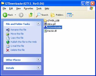
3-4 Writing Screen Data
1 Click the "GTDownLoader.exe" in the folder where the file has been
expanded.
2 The message "Execute Download?" will be displayed in the prompt
screen for the screen data. Click the "OK" button.
3 A progress screen will be displayed. Wait until the transfer of the data is
completed.
4 Click the "OK" button on completion of data transfer.
5 End.
9HL-G1 Series User’s Manual (Console-dedicated Version)
4. Sensor Connections and Initial Settings
4-1 Mounting Console
For the installation of the GT Series in detail, refer to "Chapter 3 Installation and
Wiring" of the "GT-series User's Manual”.
Use the four mounting brackets and four mounting screws provided and mount the
console to the mounting plate.
GT02 Series
(1) Insert the unit into the mounting plate.
(2) Attach the mounting brackets to the grooves of the unit, and slide and fix the
brackets. Tighten the screws and fix the unit to the mounting plate securely.
Note 1) Use a No. 1 Phillips screwdriver.
Note 2) Screw tightening torque of 0.2 to 0.3 N·m
Note 3) Do not tighten the screws in excess, or otherwise the front
panel may deform and the touch switch cannot work
properly. Be sure to keep the above torque range.
Enlarged view
Phillips screwdriver
Make sure that the
direction of the
screw is correct.
GT12 Series
(1) Insert the unit into the mounting plate.
(2) Attach the mounting brackets to the grooves of the unit.
Tighten the screws and fix the unit to the mounting plate securely.
Note 1) Use a No. 1 Phillips screwdriver.
Note 2) Screw tightening torque of 0.2 to 0.3 N·m
Note 3) Do not tighten the screws in excess, or otherwise the front
panel may deform and the touch switch cannot work
properly. Be sure to keep the above torque range.
Enlarged view
Phillips screwdriver
Make sure that the
Insert the screw to direction of the
the end. screw is correct.
10HL-G1 Series User’s Manual (Console-dedicated Version)
4-2 Connecting Dedicated Console to HL-G1
For general handling information on the GT Series, refer to the GT-series User’s
Manual.
● Connecting GT02 Series to HL-G1 (Single HL-G1 Unit over RS-422)
• Make one-to-one wiring for each signal name between the HL-G1 and console
connected through a cable.
Communications line connections
HL-G1 Signal direction Console
Wiring color Signal HL-G1 Console Signal
name name
Twisted- Orange +RD Input Output +SD
pair
wire White -RD Input Output -SD
Twisted- Black +SD Output Input +RD
pair
wire White -SD Output Input -RD
• To terminate the console, connect the ground terminal "E" to the signal "-RD”.
• Set the “Terminating resistor selection” to the HL-G1 as well.
• Connect the shield of the cable to the 0 V (-) terminal of the power supply for the
console.
• No sensor number settings are required for the sensor head.
24 VDC
(Orange) +RD
(White) -RD
HL-G1
(Terminating (Black) +SD
resistor: ON) (White) -SD
GT02 Series
Connector terminal
11HL-G1 Series User’s Manual (Console-dedicated Version)
● Connecting GT12 Series to HL-G1 (More than a single HL-G1 unit over
RS-485)
• Up to four HL-G1 units can be connected.
• The console will be the terminator. Connect the ground terminal "E" to the signal
"-RD”.
• Set the “Terminating resistor selection” for the terminating HL-G1 unit only,
while turn OFF the terminating resistor for each intermediate HL-G1 unit
connected through a bus line.
• The shield of each HL-G1 extension cable is connected to the signal ground (SG)
of the sensor head. Connect the shield to the 0 V (-) terminal of the power supply
for the console.
Wire the SD and RD signal lines according to the diagram as shown
below.
(+SD and -SD are connected with a twisted pair cable and so are COM. port
+RD and -RD.) connector
• Short-circuit the +SD + RD terminals and -SD and -RD terminals.
• Connect the +SD and +RD terminals on the HL-G1 side and the
+SD and +RD terminals on the console side.
• Connect the -SD and -RD terminals on the HL-G1 side and the -SD
and -RD terminals on the console side.
Dedicated console
HL-G1 unit
24 VDC
Sensor No.01
(Black) +SD
(White) -SD
Terminator (Orange) +RD
OFF
(White) -RD
HL-G1 unit (Shield)
Sensor No.02
GT12 Series
(Black) +SD
Connector terminal
(White) -SD
Terminator (Orange) +RD
OFF
(White) -RD
HL-G1 unit (Shield)
Sensor No.04
(Black) +SD
(White) -SD
Terminator (Orange) +RD
ON
(White) -RD
(Shield)
12HL-G1 Series User’s Manual (Console-dedicated Version)
4-3 HL-G1 Settings
Before using the compact console (GT-series unit) for communication with the
HL-G1, select and set communications conditions on the HL-G1 side according to
the communications specifications.
● HL-G1 Settings for communications conditions
COM Settings
Item RS-422 (single-unit connections only) RS-485 (for multi-unit connections)
Terminating resistor
R3 (see note 1) R3 (see note 1)
selection
Specify 01 through 04 in sequence
Sensor No. Optional
(see note 2)
Baud rate 38400bps (initial value) 38400bps (initial value)
Connection mode RS-422 handshake [422-1] (default) Multiple RS-485 [485-M]
Note 1: Terminating resistor selection from R1 or R2 may improve
communication condition depending on the characteristics and length of
the cable in use or the number of sensors connected.
Do not set the termination resistor for any sensor other than that located
as terminator.
Note 2: Set the sensor numbers beginning with 01 in sequence if the sensors are
connected over RS-485. If the sensor numbers are not consecutive, they
will not be recognized and the sensors will not operate correctly.
HL-G1 setting procedure
Example) In this example, sensor head number 01 is set as terminator and used over
RS-485.
2s
R3
Terminating
resistor selection
Sensor
No. 01
Sensor No.
38400
bps
Baud rate
RS-485
Multiple
Connection input
mode
13HL-G1 Series User’s Manual (Console-dedicated Version)
4-4 Changing and Saving Display Language of Console
The console screen will display in English when the console is started with the
sensor head connected after screen data is written.
Environment settings for the console are required to change the displayed language
on the screen.
The settings are saved in the sensor. Execute the Save command after making the
settings. The settings will be lost with the sensor head turned OFF if the settings are
not saved.
When the sensor head is initialized, the displayed language will return to English.
In that case, set the language again and save it.
● Switching language
Select "Environment Setting”.
Select "Console Setting”.
Languages
• Japanese
• English
• Chinese
• Korean
Select the displayed language from
"Language”.
● Saving language settings
Select “Pro7 system” in “Sensor Setting Menu.”
(Make “No. 1” if the motel is the GT12.)
Select "Save”.
The prompt message to save the setting contents of
the entire memory will be displayed. Select "Yes" to
save the contents.
14HL-G1 Series User’s Manual (Console-dedicated Version)
5. Screen Configuration and Basic Operation
5-1 Top Menu Screen and Basic Buttons
● Top menu
GT02 top menu GT12 top menu
ÌThe top menu screen shows the above items.
The user can move to other screens through here.
Meas
Display Used to display the measurement value of the sensor connected.
Meas
Operate Used to operate the measurement control of the sensor connected. (GT02 only)
Sensor
Setting Used to make various sensor settings.
Envirnmnt
Setting
Used to make console environment settings.
Meas
Display Used to display the measurement values of all the sensors connected. (GT12 only)
[ALL]
● Basic button operation
Top Returns to the top screen.
Menu Returns to each menu screen according to each setting.
● Operation during measurement value display
Hold The measurement value display is kept on hold (not refreshed).
Timing Used to implement the same action as timing input.
Zero set Used to switch the zero set and zero set OFF.
Reset Used to reset the measurement value kept on hold.
15HL-G1 Series User’s Manual (Console-dedicated Version)
5-2 Basic Console Operation
Moving between Setting Screens
The operation screen is of hierarchic structure.
Touch the Up and Down Keys ( ) to go to the target screen and make
necessary settings.
····· The value of each item in the sensor setting menus (Pro1 through Pro7) will
increase by 1.
····· The value of each item in the sensor setting menus (Pro 1 through Pro7) will
decrease by 1.
【Pro1】
Moving between
setting screens
【Pro2】
Changing Sensor Head Number (GT12 Only)
To move between sensor head numbers, touch the Left and Right Keys ( ).
····· Press this key to go to the sensor head number that is 1 larger.
····· Press this key to go to the sensor head number that is 1 smaller.
Sensor address selection
16HL-G1 Series User’s Manual (Console-dedicated Version)
Selection
This section provides information on how to select the target item from multiple
choices.
[Selection from a few choices]
The selectable item changes as shown each time the key
is touched.
Emis sion STOP
Emission
[Selection from many choices]
The selectable item changes as shown each time the Up
Key ( ) is touched.
1 4 16 64 256 1024
Press the Down Key ( ) to change the direction of
selection.
The value will return to the default value by touching
the part (where the set value is displayed) between
the Up and Down Keys.
17HL-G1 Series User’s Manual (Console-dedicated Version)
Numeric Input Set value
This section provides information on how to
input numeric values, such as limit values and
offset values. The keyboard will be displayed
Decimal point Enter
for items for which numeric input is possible.
1 Touch the frame above the set value.
The system is ready to accept numeric input, and the
cursor starts flashing.
2 Enter the integer part from the keyboard.
3 Touch the decimal ( ) on the keyboard.
Input after the decimal point is acceptable. Input the
value.
4 Touch the Enter Key ( ) after the value is
ENT
input.
The setting will be entered.
* To cancel the numeric input, touch the Esc Key
( ).
ESC
* To clear the input, touch the CLR Key ( ). Then CLR
the user can input the desired value again.
* To clear the input, touch the BS Key ( BS ). Then the
user can input the desired value again.
18HL-G1 Series User’s Manual (Console-dedicated Version)
5-3 Console-dedicated Functions
Output setting menu
(GT-12 setting screen)
● Display console measurement value
Use this function to fix the console measurement
value after the decimal point to 0.
Set this item to disable the change in the display
of the minute measurement value of the console.
Set value: FULL, Set 1, Set 2, and Set 3
[FULL] The full value down to the fourth decimal place is displayed.
[Set 1] The fourth decimal point is fixed to 0.
[Set 2] The third and fourth decimal points are fixed to 0.
[Set 3] The second, third, and fourth decimal points are fixed to 0.
Select "FULL." Select "Set 2."
• These settings are memory-dependent. Make settings for each memory number if
memory change is used.
Environment setting menu
zzz
(GT-12 setting screen)
● Number of units connected (GT12 only)
Use this function to specify the number of sensor
heads to be connected to the console and operated.
It is necessary that the sensor head numbers are
set correctly.
Set value: 1, 2, 3, 4
19HL-G1 Series User’s Manual (Console-dedicated Version)
● Panel lock
Use this function to prevent set value changes with
console key manipulation. It is possible to move
between screens.
Set value: ON, OFF
● Touch beep
Use this function to enable or disable the touch beep.
Set value: ON, OFF
● Language
Use this function to select the display language.
Set value: Japanese, English, Korean, Chinese
● Backlight color selection (GT02 only)
Use this function to select the switching method of
backlight colors according to the state of judgment
2 of the sensor head.
Set value: White /Green (fixed), OUT2ON red,
OUT2OFF red.
[White/Green (fix)] The backlight color is set according to the default of the
display unit.
[OUT2ON red] The backlight color is changed to red by a measurement
value that turns OUT2 ON.
[OUT2OFF red] The backlight color is changed to red by a measurement
value that turns OUT2 FF.
• The ON/OFF operating conditions of OUT2 are set with "Judgment output
selection" and "Displacement judgment”.
● Type and Version display
Use this function to display the model number of
each sensor head connected and the software version
for the sensor head.
Each set value need to be saved in the sensor head.
Be sure to execute “Pro7: System setting” → “Save” after making settings.
(Set and save “Sensor No. 01” (No. 1) in the case of connecting the GT12 to a
number of sensor heads over RS-485.
Keep in mind that ettings will be lost with the sensor head turned OFF unless the
settings are saved.
20HL-G1 Series User’s Manual (Console-dedicated Version)
6. Screen Transition Charts
This section provides screen transition charts of the console dedicated to HL-G1.
For details of each function, refer to the HL-G1 User's Manual provided with the
sensor head.
6-1 GT02 Screen Transition
●Transition from top screen to each menu screen
Environment setting menu
Measurement value display Sensor setting menu
Memory change
Pro1 Sensing settings
Pro2 Data processing settings
Measurement value operation
Pro3 Output settings
Pro4 Analog settings
Pro5 Alarm setting
Pro7 System setting
21HL-G1 Series User’s Manual (Console-dedicated Version)
● Setting item screen for each setting menu (for GT02 use)
Pro1: Sensing setting menu Pro2: Data processing menu Pro3: Output setting menu
Sampling cycle Average times Judgment output selection
Shutter time Analysis mode Displacement judgment (Threshold a)
Span Displacement judgment (Threshold b)
Offset Hysteresis
Judgment output OFF delay
Panel measurement value display
Console measurement value display
22HL-G1 Series User’s Manual (Console-dedicated Version)
Pro4: Analog setting menu Pro5: Alarm setting menu Pro7: System setting menu
Analog output selection Analog output at alarm Timing mode
Analog scaling (current) Digital output at alarm Laser control
Analog scaling (voltage) Alarm delay times Eco mode
Initialization
Environment setting menu
Save
Console settings (1/2)
Console settings (2/2)
Type No. and Version
23HL-G1 Series User’s Manual (Console-dedicated Version)
6-2 GT12 Screen Transition
● Transition from top screen to each menu screen
Top screen
Environment setting menu
Sensor setting menu
Measurement value display [ALL]
Sensor setting menu [NO. 1]
Memory change
Pro1 Sensing setting
Measurement value display menu
Pro2 Data processing setting
Pro3 Output settings
No. 1 display
Pro4 Analog settings
No. 1 operation
Pro5 Alarm setting
Pro7 System setting
24HL-G1 Series User’s Manual (Console-dedicated Version)
● Setting item screen for each setting menu (for GT12 use)
Pro1: Sensing setting menu Pro2: Data processing menu Pro3: Output setting menu
Sampling cycle Average times Judgment output selection
Shutter time Analysis mode Displacement judgment (Threshold a)
Span Displacement judgment (Threshold b)
Offset Hysteresis
Judgment output OFF delay
Panel measurement value display
Console measurement value display
25HL-G1 Series User’s Manual (Console-dedicated Version)
Pro4: Analog setting menu Pro5: Alarm setting menu Pro7: System setting menu
Analog output selection Analog output at alarm Timing mode
Analog scaling (current) Digital output at alarm Laser control
Analog scaling (voltage) Alarm delay times Eco mode
Environment setting menu Initialization
Save
No. of units connected
Console settings
Type No. and Version
26HL-G1 Series User’s Manual (Console-dedicated Version) MEMO 27
HL-G1 Series User’s Manual (Console-dedicated Version)

Revision history
  Released date              Revision No.
    October 2010              First release

                                                         28
October 2010
You can also read