Chapter 4: Spanning Tree Design Guidelines for Cisco NX-OS Software and Virtual PortChannels
←
→
Page content transcription
If your browser does not render page correctly, please read the page content below
Design Guide

                                                                 Chapter 4:
              Spanning Tree Design Guidelines
               for Cisco NX-OS Software and
                    Virtual PortChannels

© 2012 Cisco and/or its affiliates. All rights reserved. This document is Cisco Public Information.       Page 1 of 20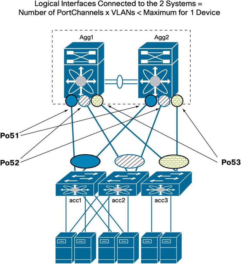
Contents
                        Fundamental Spanning-Tree Concepts ................................................................................................................. 3
                            MST Compared to Rapid PVST+ .......................................................................................................................... 3
                            MST Concepts ...................................................................................................................................................... 4
                              Instances .......................................................................................................................................................... 5
                              Regions ............................................................................................................................................................ 5
                            MST Configuration Best Practices ........................................................................................................................ 8
                        VLAN Ranges in Cisco NX-OS Software ................................................................................................................ 9
                            VLAN Ranges and MST Regions .......................................................................................................................... 9
                        Special Considerations for Spanning Tree with vPCs........................................................................................ 10
                            How Spanning Tree Works in a vPC Deployment ............................................................................................... 10
                               Spanning-Tree Port Roles in Sample vPC Topologies ................................................................................... 11
                            Type-1 Misconfiguration: Global and Interface Specific ...................................................................................... 13
                            Rapid PVST+ and vPC Best Practices................................................................................................................ 15
                            MST and vPC Best Practices .............................................................................................................................. 15
                            EtherChannel Misconfiguration Guard ................................................................................................................ 15
                        Pathcost Method Long .......................................................................................................................................... 17
                        Scaling Considerations ......................................................................................................................................... 17
                            Logical Interfaces or BPDU States...................................................................................................................... 17
                              Spanning-Tree Scalability with vPC Compared to Non-vPC Designs ............................................................ 18
                        Summary Checklist for Spanning Tree in a vPC Deployment ........................................................................... 19

© 2012 Cisco and/or its affiliates. All rights reserved. This document is Cisco Public Information.                                                                                     Page 2 of 20
Fundamental Spanning-Tree Concepts
                        The first important choice to make in the design of a data center network is the spanning-tree choice. It is beyond
                        the scope of this document to describe the spanning-tree algorithms in detail. At the time of this writing, the choice
                        is between these two algorithms:

                              ●   Rapid Per-VLAN Spanning Tree Plus (PVST+): Information about Rapid PVST+ is available at
                                  http://www.cisco.com/en/US/partner/docs/switches/datacenter/sw/4_1/nx-
                                  os/layer2/configuration/guide/l2_pvrstconfig.html.
                              ●   Multiple Spanning Tree (MST): Information about MST is available at
                                  http://www.cisco.com/en/US/partner/docs/switches/datacenter/sw/4_1/nx-
                                  os/layer2/configuration/guide/l2_mstpconfig.html.
                        This document does not discuss Rapid PVST+ in detail because this protocol is already well known in the industry.

                        MST is discussed in detail here for the following reasons:

                              ●   With virtual PortChannel (vPC) deployments, VLAN load balancing is achieved automatically with no need
                                  to change spanning -tree priorities. Spanning-tree VLAN load balancing is much easier in Rapid PVST+
                                  than it is in MST. With vPC topologies, this advantage is not applicable.
                              ●   MST scales better than Rapid PVST+ because the switch generates only one Bridge Protocol Data Unit
                                  (BPDU), which summarizes all the necessary information for the specific instance. With the increase in size
                                  of the Layer 2 domain, MST may become of greater interest because of its greater scalability and its
                                  capability to maintain a regional topology.

                        MST Compared to Rapid PVST+
                        MST allows you to assign two or more VLANs to a spanning-tree instance. MST is not the default spanning-tree
                                                                                          ®
                        mode; Rapid PVST+ is the default mode on Cisco switches.

                        MST instances with the same name, revision number, and VLAN-to-instance mapping combine to form an MST
                        region. The MST region appears as a single bridge to spanning-tree configurations outside the region.

                        The advantages of MST over Rapid PVST+ are as follows:

                              ●   MST is an IEEE standard.
                              ●   MST is more resource efficient. In particular, the number of BPDUs transmitted by MST does not depend on
                                  the number of VLANs, as Rapid PVST+ does.
                              ●   MST decouples the creation of VLANs from the definition for forwarding the topology.
                              ●   MST simplifies the deployment of stretched Layer 2 networks, because of its ability to define regions.
                        For all these reasons, it is advisable for many deployments to migrate to an MST-based topology.

                        Table 1 summarizes the differences between MST and Rapid PVST+.

                        Table 1.       MST Compared to Rapid PVST+

                                                                             MST                                            Rapid PVST+

                         Number of instances                                 Typically 2 are enough                         1 per VLAN

                         Scalability                                         Much greater than Rapid PVST+ (see limits)

                         Interoperability with multichassis                  Yes, but make sure that the MST region         Yes
                         EtherChannels with vPC ports                        definition matches for primary and secondary
                                                                             vPC peers

© 2012 Cisco and/or its affiliates. All rights reserved. This document is Cisco Public Information.                                       Page 3 of 20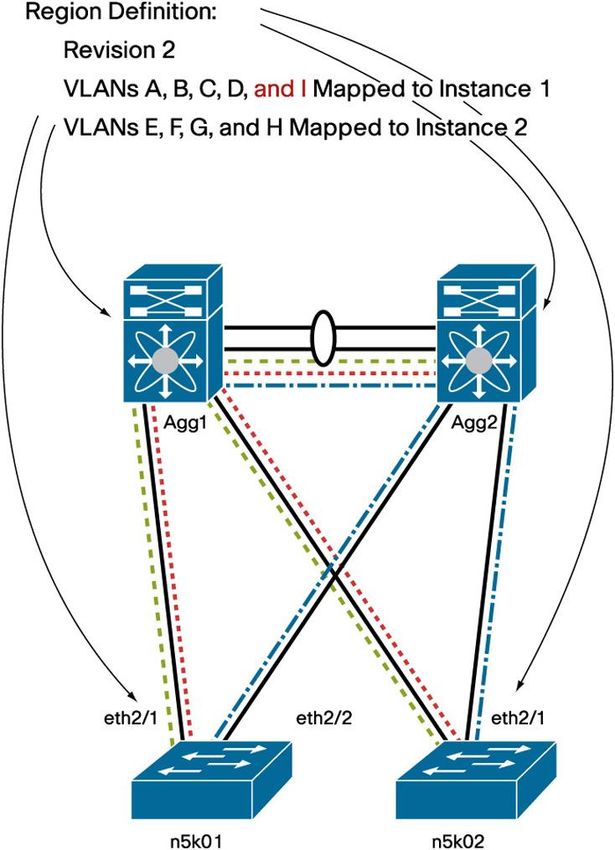
MST                                                 Rapid PVST+
                         Separation between VLAN creation and                Yes                                                 No
                         topology definition

                         Ease of implementation of per-VLAN load             Requires the definition of 2 instances and of the   Easier to deploy for VLAN load balancing in
                         balancing in spanning-tree topologies               VLAN-to-instance mapping                            classic spanning-tree designs
                                                                             (In vPC deployments, VLAN load balancing is         (In vPC deployments, VLAN load balancing is
                                                                             not needed any more.)                               not needed any more.)
                         Configuration complexity                            More complex because of the need to maintain        Easier
                                                                             the region configuration across all switches in
                                                                             the Layer 2 domain; The network administrator
                                                                             needs to manually ensure that vPC peers are
                                                                             configured identically

                         Integration of large Layer 2 domains                Easier, due to the concept of regions               More convoluted because a single device
                                                                                                                                 becomes the root for the whole Layer 2 domain;
                                                                                                                                 no possibility to create Layer 2 regions

                        Rapid PVST+ offers slightly better flexibility for load balancing VLANs on a typically V-shape spanning-tree
                        topology. With the adoption of vPC, this benefit is marginal because topologies are becoming intrinsically loop free,
                        at which point the use of per-VLAN load balancing compared to per-instance load balancing is irrelevant (with vPC,
                        all links are forwarding in any case).

                        MST Concepts
                        With IEEE 802.1s, you can create an instance, which means a number, to represent the topology, and you can
                        map VLANs to this instance (Figure 1).

                        Figure 1.      Traditional MST Design with Instance Load Balancing

                        Figure 1 shows the topology according to IEEE 802.1s, or MST. The instance that represents the topology at the
                        left is MST 1. VLAN A, B, C, and D are mapped to MST 1. At the right of the figure you can see the forwarding
                        topology for MST 2.

                        If you do show spanning-tree VLAN A from the access layer, you see that the root bridge is Agg1. If you type the
                        same command for VLAN E on the same switch, you see that the root bridge is Agg2. This difference occurs
                        because VLAN A and VLAN E are mapped to two different instances.

© 2012 Cisco and/or its affiliates. All rights reserved. This document is Cisco Public Information.                                                                  Page 4 of 20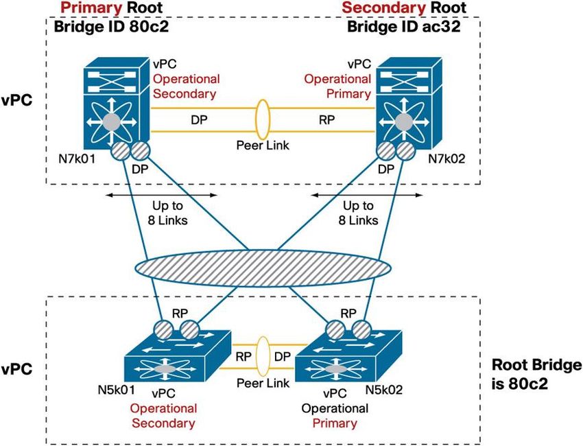
The main difference between MST and Rapid PVST+ is that in Rapid PVST+, whenever you create a VLAN, an
                        instance (topology) is automatically created, and mapping is not required. MST makes an abstraction between the
                        topology and the VLANs that are carried over that topology (instance).

                        Instances
                        Instances are created with a simple statement:
                              instance 1 vlan 1-1000

                        This configuration maps VLANs 1 through 1000 to instance 1. Whether or not VLANs 1, 2, 3, etc. exist is irrelevant.
                        After this topology is created, the VLANs can be created and assigned to trunks, but they do not have to be.
                        The switches maintain the topology for instance 1 regardless.

                        This configuration maps VLANs 1 through 500 to instance 1, and VLANs 501 through 1000 to instance 2:
                              instance 1 vlan 1-500
                              instance 2 vlan 501-1000

                        The shape of the topology for instance 1 and for instance 2 does not depend on whether the VLANs are trunked.
                        It strictly depends on the priority definition for that instance.

                        For example, you can create the topology shown in Figure 1 by using the following configuration:
                              nexus7k01(config)#spanning-tree mst 1 root primary
                              nexus7k01(config)#spanning-tree mst 2 root secondary

                              nexus7k02(config)#spanning-tree mst 1 root primary
                              nexus7k02(config)#spanning-tree mst 2 root secondary

                        MST uses a special instance to help ensure communication between regions: instance 0. You do not have to worry
                        about instance 0, except that you may want to decide which device should be the root for instance 0 in a
                        multi-region topology.

                        Regions
                        As previously mentioned, the main enhancement introduced by MST is that several VLANs can be mapped to a
                        single spanning-tree instance. As many instances can be defined as there are forwarding topologies (typically,
                        there are two forwarding topologies).

                        A region is a configuration consisting of the list of instances and associated VLAN mappings (and, incidentally, also
                        a revision number). No automatic propagation of this mapping exists; it is the administrator’s job to make sure that
                        the configuration is properly maintained across all the switches that are part of the same region.

                        For example, the following configuration fully defines a region:
                              spanning-tree mst configuration
                               name dc1
                               revision 1
                               instance 1 vlan 1-1000

                        In this region, only one instance is defined, instance 1, and VLANs from 1 to 1000 are associated with this
                        spanning-tree topology.

© 2012 Cisco and/or its affiliates. All rights reserved. This document is Cisco Public Information.                                    Page 5 of 20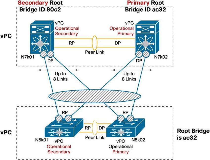
Another switch connected to the region previously defined can be configured as follows:
                              spanning-tree mst configuration
                               name dc1
                               revision 1
                               instance 1 VLAN 1-500
                               instance 2 VLAN 501-1000

                        This configuration defines a different region than the one that had only one instance configured. The
                        communication between the two MST regions uses instance 0 and the ports interconnecting the two switches are
                        boundary ports.

                        Note:       For switches to belong to different regions, it is enough that the revision number be different.

                        This particular aspect of MST may appear intimidating because it is possible to have different regions within the
                        same Layer 2 topology as the result of a change in the VLAN mapping in one of the switches. In reality, while
                        changing the VLAN mapping causes some minor disruption, the forwarding topology always converges to help
                        ensure connectivity between hosts, as Figure 2 illustrates.

                        Figure 2.      In MST Different Region Mappings Define Different Regions

                        In Figure 2, Agg1 is configured with, for example, VLAN A, B, C, and D belonging to topology 1, and E, F, G, and H
                        mapped to instance 2 (topology 2). The forwarding topology of each instance is color coded in the figure: the
                        dashed line represents instance 1, and the dash-dot line represents instance 2.

© 2012 Cisco and/or its affiliates. All rights reserved. This document is Cisco Public Information.                                    Page 6 of 20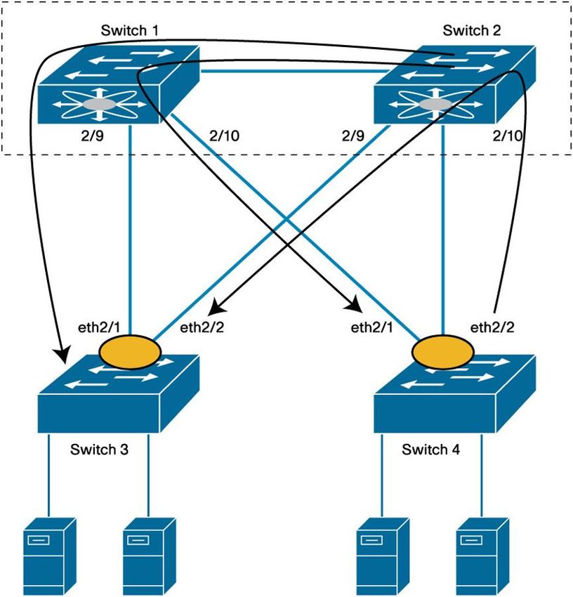
If Agg1 is configured with VLANs A, B, C, D, and I as part of topology 1, then the two switches appear to belong to
                                                                                                                                       ®
                        separate regions, as the right portion of the figure illustrates. This configuration will make the Cisco Nexus 5000
                        Series Switches n5k01 and n5k02 elect Agg2 as their regional root, so the ports connecting to it are forwarding for
                        both instances 1 and 2. The ports connecting to Agg1 become boundary ports, and they are blocking on both
                        nk501 and nk502. This approach is different from the original topology but still provides connectivity.

                        Now the administrator configures Agg2 for the new topology (Figure 3).

                        Figure 3.      Migrating an Existing MST Topology in order to Define a Unique Region

                        The left part of the figure shows that as a result of the configuration on Agg2, Agg1 and Agg2 now are part of the
                        same region, while n5k01 and n5k02 belong to the original region, which is split because n5k01 and n5k02 are not
                        directly connected. As a result, all VLANs are forwarding on the master port on n5k01 and n5k02. Quoting IEEE,
                        “A Master Port provides connectivity from the Region to a CIST Root that lies outside the region.” This topology is
                        not the final one, but it still provides network connectivity to the end host.

                        The administrator now configures n5k01, and as a result n5k01 joins the region, and as a result instance 1 is
                        forwarding on eth2/1 on n5k01 and blocking on eth2/2; n5k02 is still in a different region, so all VLANs are
                        forwarding on eth2/1, the master port.

                        Finally, n5k02 is configured, and it joins the region, resulting in exactly the same topology as at the beginning of the
                        configuration change (Figure 4).

© 2012 Cisco and/or its affiliates. All rights reserved. This document is Cisco Public Information.                                        Page 7 of 20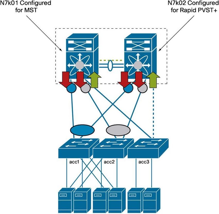
Figure 4.      Final MST Topology After All Switches Have Been Migrated to the Same Region Definition

                        Although a temporary topology flapping as a result of region definition is minimally disruptive, it can also be
                        avoided altogether by defining the regions at the deployment phase for all VLANs 1 through 4094 (0 and 4095 are
                        reserved). This definition exerts no load on the system and does not require definition of all the VLANs; VLANs can
                        be created and assigned to trunks later with no disruption.

                        MST Configuration Best Practices
                        MST configuration requires the following steps:

                              ●   Define a region configuration to be copied to all the switches that are part of the Layer 2 topology.
                              ●   As part of the region configuration, decide to which instance all VLANs 1 through 4096 belong. In typical
                                  deployments, you would need to define two instances (in a vPC deployment, you need to define only one).
                              ●   Copy the region configuration on all the switches as needed. It is very unlikely that you will ever have to
                                  modify this configuration after you have defined it.
                              ●   Define primary and secondary root switches for the instances that you have defined, as well as for instance
                                  0. Typically, the primary root for MST 0 and MST 1 is one aggregation switch, and the secondary root is the
                                  redundant aggregation switch.
                              ●   Preprovision all VLAN (1 through 4094) mappings and topologies and then create VLANs later as needed:
                              spanning-tree mode mst

© 2012 Cisco and/or its affiliates. All rights reserved. This document is Cisco Public Information.                                       Page 8 of 20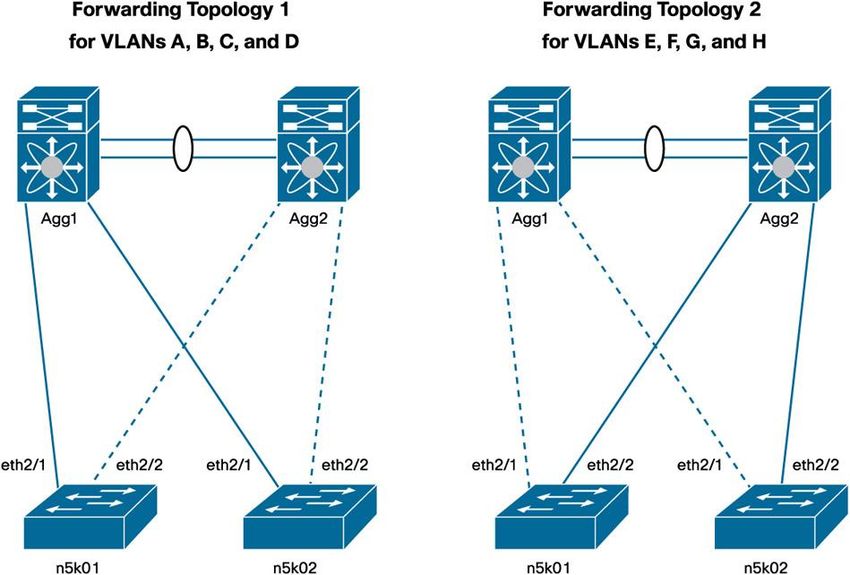
spanning-tree mst configuration
                                  name dc1
                                  revision 1
                                  instance 1 vlan 1-4096

                              spanning-tree mst 0-1 root primary

                        VLAN Ranges in Cisco NX-OS Software
                        In its current implementation, the Cisco Nexus product family supports VLANs in the ranges 1 through 3967 and
                        4048 through 4093.

                        You can find the ranges of reserved VLANs by entering this command:
                              tc-nexus5k01# show vlan internal usage

                              VLAN                 DESCRIPTION
                              ---------            -------------------------------------------------------
                              3968-4031            Multicast
                              4032                 Online diagnostics vlan1
                              4033                 Online diagnostics vlan2
                              4034                 Online diagnostics vlan3
                              4035                 Online diagnostics vlan4
                              4036-4047            Reserved
                              4094                 Reserved

                        Note:       For more information, see http://www.cisco.com/en/US/partner/docs/switches/datacenter/sw/4_2/nx-
                        os/layer2/configuration/guide/Cisco_Nexus_7000_Series_NX-
                        OS_Layer_2_Switching_Configuration_Guide_Release_4.2_chapter3.html#con_1273370.

                        The Cisco Nexus 5000 Series hardware supports up to 512 VLANs whose numbers can be selected from the
                        ranges listed here. Up to 32 of these VLANs can be used for VSAN purposes, in which case they are not available
                        any more for regular IP traffic. In addition, some VLANs are used for internal communication. Thus, a combined
                        total of 505 VLANs and VSANs can be configured by the user.

                        Even if the Cisco Nexus 5000 Series supports 505 VLANs, you can configure an MST region for the full range of
                        more than 4000 VLANs previously listed.

                        VLAN Ranges and MST Regions
                                                   ®
                        In the Cisco Catalyst product family, the reserved VLAN range is different from the Cisco NX-OS VLAN range
                        (for more information, see
                        http://www.cisco.com/en/US/docs/switches/lan/catalyst6500/ios/12.1E/native/configuration/guide/vlans.html).

                              ●   VLANs 1002 through 1005 are reserved.
                              ●   In Cisco NX-OS, the MST instance mapping looks like this:
                              instance 1 vlan 1-3967,4048-4093
                              ●   In Cisco Catalyst products, the MST instance mapping looks like this:
                                  instance 1 vlan 1-4094

© 2012 Cisco and/or its affiliates. All rights reserved. This document is Cisco Public Information.                               Page 9 of 20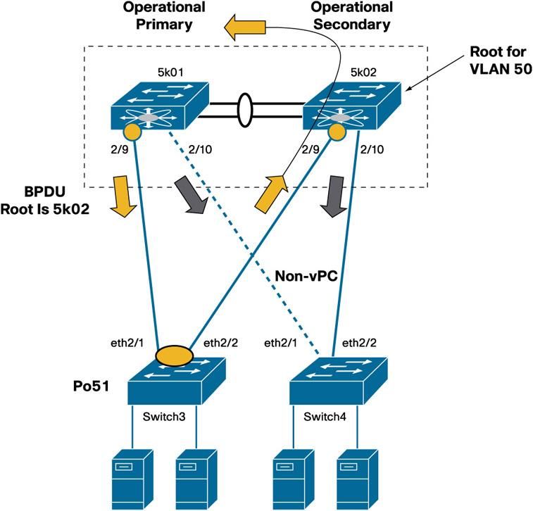
If you have a Cisco Catalyst switch connected to a Cisco Nexus switch, you need to configure the MST regions on
                        the Cisco Catalyst switches without the Cisco NX-OS reserved VLANs, so you have to copy the Cisco NX-OS
                        instance mapping to the Cisco Catalyst switch configuration.

                        Special Considerations for Spanning Tree with vPCs
                        Even if the Cisco Nexus devices are configured for vPC, each device preserves its root or secondary root role or
                        whichever priority it has as defined by the spanning-tree configuration.

                        The main difference between a vPC configuration and a non-vPC configuration is in the forwarding behavior of the
                        vPC peer link and the BPDU forwarding behavior of vPC member ports only.

                        Non-vPC ports on a vPC-configured switch behave in the same way as on a regular switch, except that the vPC
                        peer link is always forwarding, which may require a slightly different (but still valid) topology.

                        How Spanning Tree Works in a vPC Deployment
                        A vPC deployment has two main spanning-tree modifications that matter:

                              ●   vPC imposes the rule that the peer link should never be blocking because this link carries important traffic
                                  such as the Cisco Fabric Services over Ethernet (CFSoE) Protocol. The peer link is always forwarding.
                              ●   For vPC ports only, the operational primary switch generates and processes BPDUs. The operational
                                  secondary switch forwards BPDUs to the primary switch.
                        Figure 5 provides an example.

                        In this example, 5k01 and 5k02 are configured for vPC. Ports eth2/9 on both switches are vPC member ports, and
                        ports eth2/10 are regular spanning-tree ports.

                        Switch 5k01 is the operational primary switch, but 5k02 is the root for VLAN 50 and is the operational secondary
                        switch. On vPC ports 2/9, the spanning-tree behavior previously described applies. On regular ports 2/10, the
                        regular spanning-tree behavior applies.

                        Because of vPC, the operational secondary switch cannot send BPDUs from port 2/9, nor it can process them; if a
                        BPDU arrives on port 2/9, the secondary switch sends it to the primary switch. Also, the primary switch is the one
                        that can generate BPDUs to the vPC ports.

                        So although 5k02 is the root for VLAN 50, only 5k01 is allowed to send the BPDUs from 5k02 to port 2/9.

© 2012 Cisco and/or its affiliates. All rights reserved. This document is Cisco Public Information.                                    Page 10 of 20
Figure 5. Spanning-Tree Behavior with vPC
Switch 5k02 can send BPDUs on port 2/10 because this port is not part of a vPC.
Switch 5k01 will announce 5k02 BPDUs with the bridge ID of 5k02, so from the viewpoint of Switch3 the root can
be reached through Po51, and the bridge ID of the root is that of 5k02. Switch3 receives the BPDUs from the root
through port eth2/1 on Po51.
Spanning-Tree Port Roles in Sample vPC Topologies
This section provides some examples of forwarding topologies with various spanning-tree root and vPC primary
and secondary switch placements. This topology is a dual-sided vPC deployment with vPC running on Cisco
Nexus 7000 and 5000 Series Switches (Figure 6).
In this topology, 7k01 is the root, and the vPC operational secondary switch. As a result, the peer link to the
operational primary switch is a designated port. The PortChannel to the access layer is a designated port on both
7k01 and 7k02 (since they appear as a single spanning-tree entity to the access switches, on vPC ports).
At the access layer, 5k01 is the operational primary switch, and 5k02 is the operational secondary switch. The peer
link on 5k01 appears as a root port (because it connects to the operational primary switch), and PortChannel 51 is
also a root port because it is the path to the root.
Note: Unlike a regular spanning-tree deployment, a vPC deployment can have two root ports.
© 2012 Cisco and/or its affiliates. All rights reserved. This document is Cisco Public Information. Page 11 of 20Figure 6. Spanning-Tree Topology in a Double-Sided vPC Design with Mismatched vPC Primary and STP Root
If you make 7k02 the root and7k01 the secondary root, the topology changes as shown in Figure 7.
As Figure 7 shows, the peer link on 7k01 to 7k02 is now a root port, because 7k02 is the primary switch, and it is
the root switch.
On the access layer, the Cisco Nexus 5000 Series Switch now sees ac32 as the root device.
Figure 7. Spanning-Tree Topology in a Double-Sided vPC Design with vPC Primary and STP Root on the Same Switch
© 2012 Cisco and/or its affiliates. All rights reserved. This document is Cisco Public Information. Page 12 of 20Type-1 Misconfiguration: Global and Interface Specific
In a vPC deployment, ports can form a vPC only if the consistency rules are met. There are two types of
consistency rules: global rules and interface-specific rules.
● Global inconsistencies: A Type-1 global inconsistency prevents all vPCs from forming (but does not affect
non-vPC ports).
● Interface-specific inconsistencies: Type-1 interface-specific inconsistencies affect only the interface itself.
Global inconsistencies are as follows (Figure 8):
tc-nexus5k01# show vpc consistency-parameters global
Legend:
Type 1: vPC will be suspended in case of mismatch
Name Type Local Value Peer Value
------------- ---- ---------------------- -----------------------
QoS 1 ([], [3], [], [], [], ([], [3], [], [], [],
[]) [])
Network QoS (MTU) 1 (9216, 2240, 0, 0, 0, (9216, 2240, 0, 0, 0,
0) 0)
Network Qos (Pause) 1 (F, T, F, F, F, F) (F, T, F, F, F, F)
Input Queuing (Bandwidth) 1 (50, 50, 0, 0, 0, 0) (50, 50, 0, 0, 0, 0)
Input Queuing (Absolute 1 (F, F, F, F, F, F) (F, F, F, F, F, F)
Priority)
Output Queuing (Bandwidth) 1 (50, 50, 0, 0, 0, 0) (50, 50, 0, 0, 0, 0)
Output Queuing (Absolute 1 (F, F, F, F, F, F) (F, F, F, F, F, F)
Priority)
STP Mode 1 Rapid-PVST Rapid-PVST
STP Disabled 1 None None
STP MST Region Name 1 dc1 dc1
STP MST Region Revision 1 3 3
STP MST Region Instance to 1
VLAN Mapping
STP Loopguard 1 Disabled Disabled
STP Bridge Assurance 1 Enabled Enabled
STP Port Type, Edge 1 Normal, Disabled, Normal, Disabled,
BPDUFilter, Edge BPDUGuard Disabled Disabled
STP MST Simulate PVST 1 Enabled Enabled
Allowed VLANs - 1,10-14,21-24,30,50,60 1,10-14,21-24,30,50,60
Thus, it is advisable to preprovision VLAN mappings on MST as is usual in existing MST deployments.
Remember that vPC inconsistencies affect only vPC member ports, not the regular switch ports.
© 2012 Cisco and/or its affiliates. All rights reserved. This document is Cisco Public Information. Page 13 of 20Figure 8. Type-1 Global Misconfiguration Example
Interface-specific inconsistencies are as follows:
tc-nexus5k01# show vpc consistency-parameters interface po51
Legend:
Type 1: vPC will be suspended in case of mismatch
Name Type Local Value Peer Value
------------- ---- ---------------------- -----------------------
STP Port Type 1 Default Default
STP Port Guard 1 None None
STP MST Simulate PVST 1 Default Default
lag-id 1 [(7f9b, [(7f9b,
0-23-4-ee-be-1, 8033, 0-23-4-ee-be-1, 8033,
0, 0), (7f9b, 0, 0), (7f9b,
0-23-4-ee-be-2, 8033, 0-23-4-ee-be-2, 8033,
0, 0)] 0, 0)]
mode 1 passive passive
Speed 1 10 Gb/s 10 Gb/s
Duplex 1 full full
Port Mode 1 trunk trunk
Native Vlan 1 1 1
© 2012 Cisco and/or its affiliates. All rights reserved. This document is Cisco Public Information. Page 14 of 20Shut Lan 1 No No
Allowed VLANs - 10-14,21-24,30,50-51,6 10-14,21-24,30,50-51,6
If any of these parameters differ between vPC peers, the vPC does not forward traffic.
Rapid PVST+ and vPC Best Practices
When configuring Rapid PVST+ with vPC, follow these best practices:
● Associate the root role on the aggregation layer as usual and it is preferred to match the vPC primary and
secondary roles with root and secondary root. Remember that if a peer link fails, the vPC ports on the
secondary switch are shut down, so make sure that the topology works regardless of which vPC peer is the
operational secondary switch.
● Two options are available for non-vPC VLANs to avoid the scenario in which the switch virtual interface
(SVIs) for non-VPC VLANs are shut down if the peer link fails. You can place the non-vPC VLANs on a
backup link that is independent of and parallel to the vPC peer link. In this case, make sure to clear the peer
link from the non-vPC VLANs. Alternatively, you can use the command dual-active exclude interface-vlan
to help ensure that non-vPC SVIs stay available.
MST and vPC Best Practices
When configuring MST with vPC, you should follow the same best practices as for Rapid PVST+. In addition, you
should follow these practices:
● Associate the root and secondary root role at the aggregation layer and it is preferred to match the vPC
primary and secondary roles with root and secondary root.
● You do not need to use more than one instance for vPC VLANs.
● Make sure to configure regions during the deployment phase.
● If you make changes to the VLAN-to-instance mapping when vPC is already configured, remember to make
changes on both the primary and secondary vPC peers to avoid a Type-1 global inconsistency.
● Use the dual-active exclude interface-vlan command to avoid isolating non-vPC VLAN traffic when the
peer link is lost.
EtherChannel Misconfiguration Guard
®
A dispute mechanism was introduced for the Cisco Catalyst 6500 Series Switches in Cisco IOS Software Release
12.2(18)SXF for MST and in Cisco IOS Software Release 12.2(33)SXI for Rapid-PVST+, prior to the introduction of
vPC to deal with a scenario such as the one described here.
If upstream switch1 and switch2 are not configured for vPC, but the downstream access switches (switch3 and
switch 4) are configured with PortChannel mode on, then broadcast frames will loop back, causing duplicates as
depicted in Figure 9. The misconfiguration guard takes down the PortChannel on the downstream switch to avoid
this scenario.
The misconfiguration guard detects this scenario by seeing BPDUs with different Bridge IDs that originate on both
PortChannel links.
© 2012 Cisco and/or its affiliates. All rights reserved. This document is Cisco Public Information. Page 15 of 20Figure 9. Etherchannel Misconfiguration Guard
When Switch1 and Switch2 are configured as a vPC system, Cisco Catalyst Switch3 and Switch4 see the BPDU
coming only from one port: the port connecting to the primary vPC switch. Alternatively, when the vPC peer
switches are disconnected (dual-active scenario), both start generating BPDUs, at which point EtherChannel
misconfiguration guard intervenes to shut down the links connecting to the Cisco Nexus switches because in this
case Switch1 and Switch2 would generate BPDUs with different Bridge IDs.
Because of this EtherChannel misconfiguration guard on the Cisco Catalyst platforms used to interfere with the
vPC dual-active failure scenarios whereby two Cisco Nexus switches that were previously forming a vPC system
are losing connectivity on both the peer link and the peer keepalive link. Starting from Cisco NX-OS 4.2 this
problem doesn’t exist any more.
Note: The misconfiguration guard is not really required in the case of a vPC dual-active failure, because there is
no remaining connectivity between Switch1 and Switch2; thus, this protection does not need to be implemented.
This protection is also unnecessary when the vPC peer keepalive link is up, because vPC implements a recovery
mechanism that shuts down vPC member ports on the secondary vPC peer.
If running a Cisco NX-OS release prior to 4.2 and to reduce the effect on production traffic, disable the
EtherChannel misconfiguration protection (or dispute mechanism) as shown here on the access-layer switches if
they run Cisco Catalyst switches and Cisco IOS Software (you do not need to do this on Cisco NX-OS devices):
no spanning-tree etherchannel guard misconfig
© 2012 Cisco and/or its affiliates. All rights reserved. This document is Cisco Public Information. Page 16 of 20Pathcost Method Long
If you are not using spanning-tree pathcost method long, the cost of most links in a data center is almost identical
regardless of the available bandwidth along a given path:
● 1-Gbps link = 4
● 2- Gbps links = 3
● 3- Gbps links = 3
● 4- Gbps links = 3
Considering that spanning tree was designed before the availability of 10 Gigabit Ethernet or even Gigabit
Ethernet, the default spanning-tree reference cost for a link is inadequate, as most links with 10 Gigabit Ethernet
bandwidth or bandwidth with multiples of 10 Gigabit Ethernet will appear to have the same cost.
With spanning-tree pathcost method long enabled, spanning tree calculates the best forwarding path according
to the link bandwidth to the root and not based on hop count. With this command, the cost of links is as follows
(these numbers are weights so they don’t have a specific measurement unit):
● One Gigabit Ethernet link = 20,000
● Two Gigabit Ethernet links = 10,000
● Three Gigabit Ethernet links = 6660
● Four Gigabit Ethernet links = 5000
The cost with 10 Gigabit Ethernet links is as follows:
● One 10 Gigabit Ethernet link = 2,000
● Two 10 Gigabit Ethernet links = 1,000
Scaling Considerations
Design scalability is based on various factors, including:
● Number of PortChannels supported (discussed in Chapter 3 of this guide)
● Number of VLANs supported by a switch
● Logical interface count (also called bridge state count) for the control plane of a given switch
● Oversubscription rate
Logical Interfaces or BPDU States
A logical port is the sum of the number of physical ports times the number of VLANs on each port. This value is
what produces load on the CPU because each port that includes a VLAN has to generate and process BPDUs.
The more VLANs on the trunks, the higher the load on the CPU. This load is one of the reasons you should clear
trunks from unnecessary VLANs.
The upper limit of logical ports that a switch can support depends on the spanning-tree algorithm. With Rapid
PVST+, each VLAN is a separate instance of the spanning-tree algorithm, which means that Rapid PVST+ can
support fewer VLANs than MST.
© 2012 Cisco and/or its affiliates. All rights reserved. This document is Cisco Public Information. Page 17 of 20Scalability limits are documented on the Cisco.com online page in two formats:
● Logical interfaces
● Bridge states
The Cisco Nexus 5000 Series Switch and 2000 Series Fabric Extenders use the concept of BPDU states to
express scalability limits instead of using logical interfaces. As already mentioned, the BPDU state count is
different from the logical interface count. Also remember that host ports configured for BPDU filtering do not have
any BPDU state except at link up, so the limits expressed in terms of BPDU state are an indication of how many
switch-to-switch trunks can be configured.
In the case of Rapid PVST+, the bridge state count maps exactly to the logical interface count, but in the case of
MST, the bridge state scalability really refers to the number of instances (and not VLANs) times the number of
ports.
For some of the scalability values, see the following:
● Cisco Catalyst 6500 Series:
http://www.cisco.com/en/US/partner/docs/switches/lan/catalyst6500/ios/12.2SX/release/notes/ol_14271.htm
l#wp26366.
● Cisco Nexus 7000 Series: http://www.cisco.com/en/US/partner/docs/switches/datacenter/sw/4_1/nx-
os/layer2/configuration/guide/l2_limitsapp.html.
● Cisco Nexus 5000 and 2000 Series:
http://www.cisco.com/en/US/docs/switches/datacenter/nexus5000/sw/configuration/guide/cli_rel_4_0_1a/lim
its.html.
Spanning-Tree Scalability with vPC Compared to Non-vPC Designs
When vPC is used, only the primary vPC device processes BPDUs; the secondary device simply passes them over
the peer link to the primary device. You should factor in this behavior when calculating the logical interfaces in a
vPC deployment.
As a result, when calculating scalability for a vPC deployment, you should look at the total logical interfaces for a
system composed of two vPC peer switches and compare the limits for a single device.
Using the processing power of the primary vPC device to handle both vPC peers yields the same scalability as
having two separate switches with regular spanning-tree topologies because most links are PortChannels; each
PortChannel counts as a single logical port regardless of the number of links it contains.
In addition, in these topologies spanning tree is not doing much because all links are forwarding and most failures
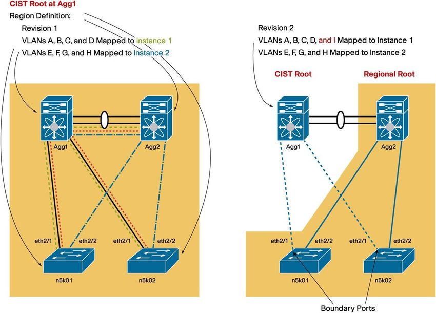
are recovered by the PortChannel logic without any need for spanning-tree intervention (Figure 10).
In Figure 10, Agg1 and Agg2 are configured as part of the same vPC or virtual switching system (VSS).
To calculate the scalability, multiply the number of vPCs times the number of VLANs for each vPC and make sure
that the result is below the maximum number of logical interfaces supported by one (and one only) of the
aggregation switches.
For example, assuming 10 VLANs per vPC, the number of logical interfaces is 3 x 10 = 30.
© 2012 Cisco and/or its affiliates. All rights reserved. This document is Cisco Public Information. Page 18 of 20Figure 10. Calculation of the Logical Interface in a vPC Design
Summary Checklist for Spanning Tree in a vPC Deployment
The ideal configuration for a vPC deployment is summarized here:
● Choose the spanning-tree algorithm, keeping in mind that MST scales better, but that Rapid PVST+ is
easier to deploy. Also you should not deploy MST unless you fully understand the region concept and Type-
1 global misconfiguration.
● Verify the VLAN range that is used in the topology and make sure that all devices are configured for the
VLAN range that is common to all platforms.
● Be mindful of non-vPC ports (orphaned ports) and consider the topology behavior for these ports and for the
associated SVIs when the peer link is lost. Take advantage of the dual-active exclude interface-vlan
command to avoid isolating non-vPC VLAN traffic when the peer link is lost.
● Preprovision MST: Make sure you understand the MST region concept and vPC Type-1 global
misconfiguration. Create the region configuration for the deployment as well as all the VLAN mappings.
VLAN creation can be performed after deployment with no disruption. Region modifications should be
limited to deployment time to reduce the need for topology recalculations and to avoid Type-1
misconfiguration.
● On the aggregation layer, create a root or a secondary root device as usual. Design the network to match
the primary and secondary roles with the spanning-tree primary and secondary switches
● Make sure pathcost method long is enabled.
© 2012 Cisco and/or its affiliates. All rights reserved. This document is Cisco Public Information. Page 19 of 20Printed in USA C07-572834-01 01/12 © 2012 Cisco and/or its affiliates. All rights reserved. This document is Cisco Public Information. Page 20 of 20
You can also read