Rope Canopy Installation Guide - ShadeFX
←
→
Page content transcription
If your browser does not render page correctly, please read the page content below
Rope Canopy Installation Guide
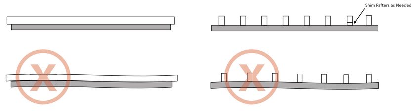
Table of Contents

      Introduction
               Objective									                                           3
               About the Product								                                    3
               How it Works									                                        3
               The Importance of Proper Installation						                  4
               Special Considerations								                               4

      Pre-installation

               System Components								 5
               Recommended Tools and Hardware						 6

      Installation

               Step 1: Mounting the Drive Beam						                        7
      		                Mounting the Drive Beam – Supplementary Notes			    9
      		                Mounting the Drive Beam – Quality Inspection				   10

               Step 2: Securing the Rope Drive						12

               Step 3: Attaching the Canopy							14

               Step 4: Positioning the Stabilizers						15

               Step 5: Securing the Stabilizers							17

      Post-installation Considerations

               Winter Storage									18
               Wind										18
               Improper Use									18
               Lubricants									18
               Cleaning									19
                                                                                REV. 03/2021

2   ShadeFX Installation Guide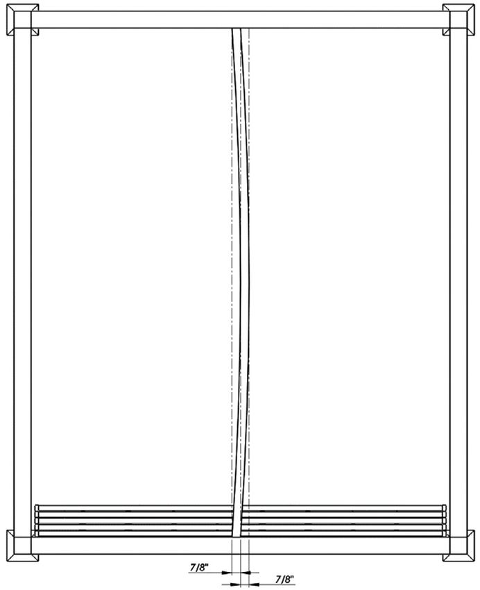
Introduction
               Objective
               To provide clear and concise installation steps for your ShadeFX retractable canopy. Installing the canopy in
               accordance with this guide will ensure a successful deployment of your system.

               About the Product
               ShadeFX retractable canopies are available in three drive options:

                        1. Manual
                        2. Rope
                        3. Motor

               Installation steps and hardware vary depending on drive option. This installation guide only pertains to
               rope canopies. Please contact ShadeFX should you require an installation guide for manual or motor canopy.

               How it Works
               The same single-track advantage applies to each drive option. Fabric panels are extended or retracted as the
               lead carrier and wing travel the drive beam. The rendering below demonstrates the extension of a canopy from a
               retracted position.

               As the lead carrier extends along the track, the fabric panels extend one at a time. Once the first fabric panel fully
               extends, the second carrier is engaged to commence extension of the second panel. The same applies to each
               carrier that follows, until the lead carrier has travelled the entire length of the drive beam.

                  1. Retracted canopy
                                                                                       2. Extending lead carrier

                  3. Engagement of second carrier                                      4. Extended canopy
REV. 03/2021

                                                                                                          ShadeFX Installation Guide    3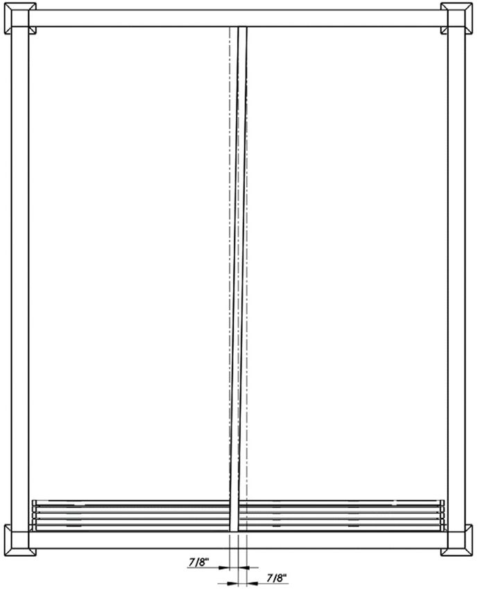
The Importance of Proper Installation
      Proper installation will preserve the life of your ShadeFX retractable canopy. Inadequate installation will result in
      avoidable and expedited wear of the system’s components.

      It is important to note that nearly all structures will vary in material and size. The installation instructions outlined in
      the guide are intended to assist with the successful deployment but are not always absolute.

      It is recommended that a complete review of the installation guide be conducted prior to installation. If there are
      questions regarding installation that are not addressed in the guide, please contact ShadeFX before continuing.

      Proper Handling
      Proper care must be taken when handling the product during installation as contact with hard, sharp,
      or abrasive surfaces could result in deformation, scratches or rips in the fabric and components of the system.

      Special Considerations
      Mounting Structure
      ShadeFX retractable canopies can weigh more than 100lbs depending on size and drive type. The structure that
      the ShadeFX retractable canopy will be mounted to must be capable of supporting the weight load of the system.
      Before installation, identify the material of the structure. Depending on material type, certain tools (drills, drill bit,
      etc.) may be required to ensure the canopy is adequately secured to the structure.

      Training & Compliance
      Most installation work is conducted above ground, from a ladder or hoist. As such, fall protection training is
      strongly recommended. Depending on the jurisdiction, licensing or regulatory requirements may apply. Parties
      installing the ShadeFX retractable canopy should review and comply with local regulations and adhere to building
      codes.

      Questions
      ShadeFX retractable canopies are a unique product with limited comparable offerings. Whether you are an
      experienced contractor or homeowner installing the system for the first time, questions may arise.

      ShadeFX Canopies: (855) 509-5509

                                                                                                                                     REV. 03/2021

4   ShadeFX Installation Guide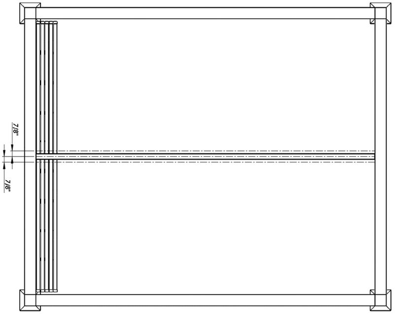
Pre-installation
               The pre-installation section is intended to educate the installer of the various components of the system,
               recommended tools and applicable hardware.

               Every ShadeFX retractable canopy will include a drive beam, canopy and hardware. Stabilizers can either be
               purchased directly from ShadeFX or made on-site from a material that matches the structure (wood, steel,
               aluminum, etc.). Please note that stabilizers play a vital role in the installation of the canopy and are explained in
               further detail later in the guide.

               System Components
               Drive Beam and Canopy
               _________________________________________________________________________________________________

                                          Drive Beam   Floating Carrier                                                G-Clip

                                                                                                                       Fixed Carrier
                                   Lead Carrier
                                                                                                                          Fixed Wing

                                End Cap

                                                                                                            Floating
                                  Leading Wing                                                               Wing

                                                        Wing Mounting Hole                                 Valance

               Canopy Stabilizers
               _________________________________________________________________________________________________

                                                                                                   Stabilizer

                                                                                                  End Cap
REV. 03/2021

                                                                                                                ShadeFX Installation Guide   5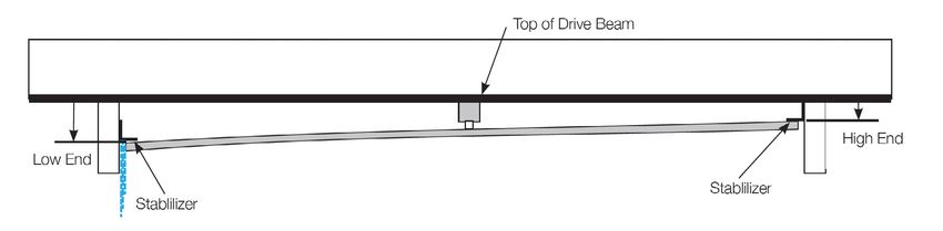
Recommended Tools
      The tool listing below is recommended to facilitate an efficient and effective installation. Certain tools may be
      substituted.

          •   Hand drill(s)                                          • Socket set
          •   Stepladder(s)                                          • ¼” Drill bits
          •   Tape or laser measure                                  • Four quick clamps large enough to secure
          •   Level                                                    your drive beam to rafter
                                                                     • Chalk line or string line

      Hardware
      Each canopy drive option is made up of differing hardware kits. The items listed below will be included for a rope
      canopy. Quantity of hardware will vary with canopy size.

       Mounting Screws (Wood Structure)                            Mounting Screws (Steel Structure)

       Rope Cleat                                                  G-Clip

       Spring Mount                                                Eye Strap

        Pulleys (Double, Single)                                   7/16 Hex Head Bolt, 7/16 Nut
                                                                                                                           REV. 03/2021

6   ShadeFX Installation Guide
Installation
               The following installation instructions are intended to assist with the installation of a rope canopy and should not
               be used as a guide to install manual or motor canopies. Please contact ShadeFX should you require installation
               instructions for a manual or motor canopy.

               The installation contains five steps. Certain steps will vary depending on canopy options selected, the material
               of the structure, etc. Each step is laid out for the most common procedure with supplementary notes for various
               customizations and options.

               STEP 1: Mounting the Drive Beam
               A) Finding the Drive Beam Location on the Structure
               To determine the location of the drive beam, measure the width of the structure at the rear. Divide the width in half
               to obtain the center point. Add 7/8” to both sides of the center and mark the structure at those points. Repeat
               the same procedures at the front of the structure. Once the 7/8” markings are established at the rear and front of
               the structure, use a chalk line to create straight lines. The chalk lines will serve as the guide for centering the drive
               beam. The drive beam will fit inside the guide lines created. Refer to Figure 1A.

               Figure 1A
               _________________________________________________________________________________________________

                                                                    Canopy Front

                                                   Left Side                              Right Side

                                             Chalk Lines                                  Centerline

                                                                    Canopy Rear
REV. 03/2021

                                                                                                           ShadeFX Installation Guide      7
B) Perpendicular vs. Parallel Rafters
The drive beam can be mounted either perpendicular or parallel to the structure rafters. If mounting to
perpendicular rafters, the span between rafters should not exceed 60”. Refer to Figure 1B. It is imperative that
the rafters are located at an equal height, otherwise the drive beam will deform when mounted. If the rafters are
of differing heights, shims should be used to create a flush/flat surface for mounting.
Figure 1B
_________________________________________________________________________________________________
Mounting Parallel to Rafters Mounting Perpendicular to Rafters
Max Spacing 60”
Drive Beam
Drive Beam
C) Marking Mounting Screw Locations on the Drive Beam for Wood Structure
On the underside of the drive beam, mark a center point at both the rear, and front end. Use a chalk line to find
the center of the drive beam. Mark and pre-drill two staggered 3/16” holes, every 24” inches, if mounting to a
parallel rafter. If mounting to perpendicular rafters, mark and pre-drill two staggered 3/16” holes at every rafter
location relative to the drive beam. Allow 3” for screw locations at front and rear of drive beam to accommodate
rope pulleys. Refer to Figure 1C.
Figure 1C
_________________________________________________________________________________________________
24” Spacing
Front Rear
Chalk Line Staggered Holes
REV. 03/2021
8 ShadeFX Installation GuideD) Securing the Drive Beam to the Structure
Using clamps, temporarily secure the drive beam to the structure, using the guide lines created in Step 1A. Using
the mounting screws, fasten the drive beam to the rafters at each pre-drilled location from Step 1C. Refer to
Figure 1D
Figure 1D
_________________________________________________________________________________________________
Step 1. Mounting the Drive Beam – Supplementary Notes
E) Finding the Drive Beam Location on the Structure for an Offset Canopy
Offset orientation is always viewed and described from the rear of the structure (retracted position). If the offset
is 2” to the right, the drive beam will be installed 2” to the right of the center point of the structure. Factoring the
offset, follow the same procedures as outlined in Step 1A. Refer to Figure 1E to see illustration of offset.
Figure 1E
_________________________________________________________________________________________________
Canopy Front
Box Frame
Centerline
Left Side Right Side
Canopy Rear
REV. 03/2021
ShadeFX Installation Guide 9F) Marking Mounting Screw Locations on the Drive Beam for Steel Structure
If mounting to a steel structure, the structure will require pre-drilled holes before installing the mounting screws.
On the underside of the drive beam, mark a center point at both the rear and front end. Use a chalk line to find the
center of the drive beam. Mark and pre-drill one centered 3/16” holes, every 24” inches, if mounting to a parallel
rafter. If mounting to perpendicular rafters, mark and pre-drill the centered 3/16” hole at every rafter location,
relative to the drive beam. Refer to Figure 1F
Figure 1F
_________________________________________________________________________________________________
Using clamps, temporarily secure the drive beam to the structure, using the guide lines created in Step 1A. Once
the drive beam is safely secured temporarily, use the pre-drilled locations on the drive beam to mark the drilling
locations on the structure. Unclamp and remove the drive beam to pre-drill the structure locations. Once all
locations on the structure are pre-drilled, temporarily secure the drive beam to the structure, using the guide lines
created in Step 1A. Using the mounting screws, fasten the drive beam to the rafters at each pre-drilled location.
Quality Inspection
You have now successfully completed the mounting of the drive beam to the structure. Before proceeding to
Step 2, answer the following questionnaire to ensure the drive beam is appropriately mounted.
• Is the drive beam level across its entire span? Refer to Figure Q1
Figure Q1
_________________________________________________________________________________________________
Parallel to Rafters Perpendicular to Rafters
Shim Rafters as Needed REV. 03/2021
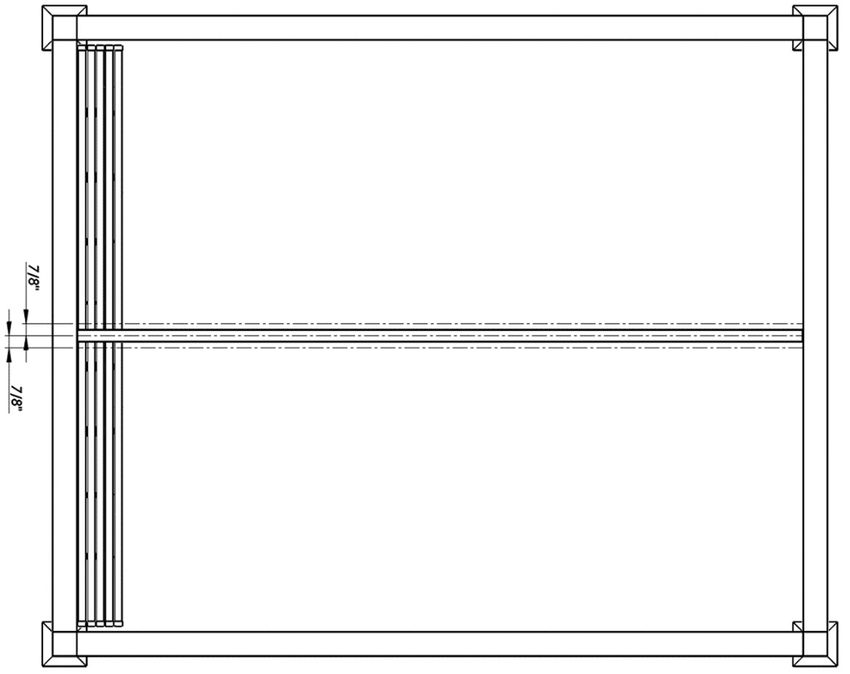
10 ShadeFX Installation Guide• Is the drive beam straight from rear to front? Refer to Figure Q2
Figure Q2
_________________________________________________________________________________________________
Straight Drive Beam
Canopy Front
Left Side Right Side
Chalk Lines Centerline
Canopy Rear
Curved Drive Beam Misaligned Drive Beam
Canopy Front Canopy Front
Left Side Right Side Left Side Right Side
Chalk Lines Centerline Chalk Lines
Centerline
Canopy Rear Canopy Rear
REV. 03/2021
ShadeFX Installation Guide 11Step 2: Securing the Rope Drive
The following illustration is provided to highlight all the components associated with the rope drive set up. Please
take a minute to review the illustration before proceeding with installation of the rope drive. Refer to Figure 2.
Figure 2
_________________________________________________________________________________________________
Rope Exit Hole
Drive Beam
Double Pulley
Rope
Rope Cleat
Single Pulley
Spring
Spring Mount
Now that you have familiarized yourself with the rope drive components, proceed with the following instructions.
A) Pull rope through the exit hole perpendicular to the track, ensuring the rope is on a level plain.
Refer to Figure 2A
Figure 2A
_________________________________________________________________________________________________
Eye Strap
Double
Pulley Rope
Exit Hole
REV. 03/2021
12 ShadeFX Installation GuideB) Position the double pulley at a location that allows the spring mount to sit at a 90-degree
angle to the double pulley. Figure 2B
C) Verify that the rope traveling down from the double pulley to the spring mount clears the
wing by at least 1” to avoid possible fabric abrasion.
Figure 2B
________________________________________________________________________________________________
Double Pulley Rope Exit Hole
D) Secure the double pulley.
E) Fully extend the lead carrier. Once the lead has travelled the entire distance of the drive beam
create slight tension on the rope, by pulling the spring mount downwards. The spring should be
extended by approximately 1/2” from its recoiled position.
F) Without alleviating the tension on the spring, secure the spring mount.
G) Mount the rope cleat at a location that is comfortable for securing the rope.
REV. 03/2021
ShadeFX Installation Guide 13Step 3: Attaching the Canopy
Once the drive beam and the rope drive mechanism have been mounted, the next step is to attach the canopy.
Each wing is to be inserted into a carrier assembly and secured together by a G-Clip. Start with the rear carrier/
wing assembly and finish with the lead carrier/wing. The lead carrier/wing is secured with a nut and bolt, instead
of a G-Clip.
Refer to Figure 3, for a six-step illustration of securing the wings to the carrier assemblies.
Figure 3
_________________________________________________________________________________________________
1. Raise wing into carrier assembly 2. Align hole in wing with hole in carrier assembly.
Once holes are aligned, insert the G-Clip
3. Rotate the G-Clip downward to lock into position 4. Secured wing to carrier assembly
5. Align hole in lead wing with hole in lead carrier assembly. 6. Secure lead wing to lead carrier assembly
Once the holes are aligned insert the bolt and fasten the nut.
REV. 03/2021
14 ShadeFX Installation GuideStep 4: Positioning the Stabilizers
It is of the utmost importance that stabilizers are properly located. Improperly installed stabilizers will result in
operation complications and avoidable damage to various components of the canopy system.
The term “deflection”, which will be used in the following procedures, refers to the bending of the wings beyond
their natural curved shape when attached to the carrier assembly. “Deflection” is achieved by increasing the
vertical distance between the top of the drive beam and top of the wing tip. The orientation and the length of the
wings determine “Deflection”.
Depending on desired rain management the orientation of the stabilizers will vary. The following procedures will
outline two orientation options. Separate deflection tables are provided for each orientation.
Orientation A: Flat Canopy
A flat orientation will deflect rain from the center of the canopy to both sides. Allow the canopy to rest in its natural
position. Refer to Table 4A to determine deflection values. If you have received deflection values directly from
ShadeFX for your system, please use those values.
Table 4A Flat orientation deflections
_________________________________________________________________________________________________
Wing Length (feet) Deflection (inches)
8 3 1/4
9 3 7/ 16
10 3 5/8
11 3 27/32
12 4 1/8
13 4 1/2
14 4 15/16
15 5 7/16
16 6
17 6 3/4
18 7 1/2
*Fabric weight and number of wings can impact prescribed deflections. A tolerance of +/- ¼” is suitable for adjustment.
Using the values obtained from the table locate the stabilizer position. The values for deflection refer to the
distance between the top of the drive beam (where mounted to structure) to the top of the wing tip. Measure in
several places along the length of the structure and verify that the measurements form a level line, parallel to the
drive beam. Refer to Figure 4A
Figure 4A
_________________________________________________________________________________________________
Top of Drive Beam
Deflection
Drive Beam
Canopy Wing
Stabilizer Stabilizer
REV. 03/2021
ShadeFX Installation Guide 15Orientation B: Tilted Canopy
A tilted orientation will help deflect rain to one side of the canopy.
Allow the canopy to rest in its natural position. Refer to Table 4B to determine deflection values. If you have
received deflection values directly from ShadeFX for your system, please use those values.
Table 4B
_________________________________________________________________________________________________
Wing Length (ft) High End Deflection (inches) Low End Deflection (inches)
8 0.5 6
9 0.5 6 3/8
10 0.5 6 5/8
11 0.5 7 1/8
12 0.5 7 5/8
12+ Not Recommended
*Fabric weight and number of wings can impact prescribed deflections. A tolerance of +/- ¼” is suitable for adjustment.
Using the values obtained from the table locate the stabilizer position. The values for deflection refer to the
distance between the top of the drive beam (where mounted to structure) to the top of the wing tip. Measure in
several places along the length of the structure and verify that the measurements form a level line, parallel to the
drive beam. Refer to Figure 4B
Figure 4B
_________________________________________________________________________________________________
Top of Drive Beam
High End
Low End
Stabilizer
Stabilizer
Common Errors When Installing Stabilizers
The following illustrations highlight common errors made when installing stabilizers.
Stabilizers Installed Underneath the Wing
Downward pressure is not achieved if the stabilizers are installed underneath the wings. This deployment will result
in chattering and visible markings/damage to the wings. Refer to illustration below.
REV. 03/2021
16 ShadeFX Installation GuideOver-stressed Wings
If stabilizers are installed with too much downward pressure, unnecessary resistance will be present when
extending and retracting the canopy. Not only will this impact the operation of the system, it will result in
deformation of the wings and can cause severe damage to carrier assembly and fabric. Refer to illustration below.
Multiple Pieces to Create One Stabilizer
Stabilizers must be one continuous surface without a break, splice or joint. Transition areas between pieces can
catch the wings, producing excessive tension of the system, compromising its performance and longevity of its
components.
Step 5: Securing the Stabilizers
Once Step 4 is complete and the stabilizers appear to be positioned in the appropriate location, tack them at
both ends and the centre. Extend and retract the canopy a couple of times to ensure enough downward pressure
is present to keep the system in place without creating unnecessary tension. Make any necessary adjustments
to address downward pressure and tension and proceed to permanently secure the stabilizers every 24”.
REV. 03/2021
ShadeFX Installation Guide 17Post-installation Considerations
The following section is intended to inform the canopy user of preventative actions that should be taken to
maintain the longevity of the canopy.
Winter Storage
ShadeFX canopies are not engineered to bear snow loads. In colder climates it is recommended the canopies
are taken down and stored for the winter. Dismount the canopy by removing the G-Clips and store in a safe place
away from the elements. The drive beam and stabilizers will not need to be removed for winter storage. Under no
circumstances should the drive beam be operated in freezing temperatures.
Before reattaching the canopy after winter storage, please inspect the canopy, drive beam and stabilizers to
ensure that they are free of debris and in working order. Inspect the canopy again after reattaching.
Wind
ShadeFX canopies are built to withstand high winds but should be retracted in winds exceeding 35mph (56kmh).
When retracting the canopy in windy situations, operation of the canopy may be more difficult. It is important that
the fabric not be blown up into the drive beam by a gust of wind, during retraction. Ensure that the fabric on the
retracting canopy folds underneath the drive beam in its usual manner.
Improper Uses of the Product
Do not hang objects such as lights, fans, heater, etc. from any part of the ShadeFX canopy or drive beam.
Do not attempt to alter or fix any part of the canopy or drive beam without receiving instruction directly from
ShadeFX.
Lubricants
Do not apply any kind of lubricants inside the drive beam or on the carriers. The system is designed and
manufactured to be lubricant free.
REV. 03/2021
18 ShadeFX Installation GuideCanopy Cleaning
Over the years stains may appear from flora or fauna. Removal of light and isolated stains can be achieved
without dismounting the canopy. If you are cleaning the entire canopy, it is recommended that you take the
canopy down.
The following steps are provided to guide the user as to the best method of cleaning the canopy, while mounted
to the system.
1. Brush off the loose dirt with soft bristle brush. DO NOT USE A STIFF BRISTLED BRUSH.
A stiff bristled brush may scuff the fabric.
2. Hose down the canopy. DO NOT USE A PRESSURE WASHER. A pressure washer
may pierce/puncture the fabric.
3. Prepare a cleaning solution of water and mild soap such as Woolite or Dawn dishwashing liquid.
4. Use soft bristle brush to clean.
5. Allow cleaning solution to soak into the fabric.
6. Rinse thoroughly until all soap residue is removed.
7. Air dry.
8. If desired, apply fabric sealant such as Fabric Guard to protect from water and stains.
The following steps are provided to guide the user as to the best method of cleaning the canopy, when
dismounting from the system.
1. Detach the canopy from the drive beam and lay on a mat larger than the canopy, such as a tarp.
2. Brush off the loose dirt with a soft bristled brush. DO NOT USE A STIFF BRISTLED BRUSH.
A stiff bristled brush may scuff the fabric.
3. Pre-soak one panel of the canopy (the fabric section between two wings) with water and a mild
soap such as Woolite or Dawn dishwashing liquid. DO NOT USE FABRIC DETRERGENT.
Fabric detergent will remove the hydrophobic sealant on the fabric.
4. Lightly scrub the fabric with a light-bristled brush. DO NOT USE A STIFF BRISTLED BRUSH.
A stiff bristled brush may scuff the fabric.
5. Wash the soap off with a hose. DO NOT USE A PRESSUE WASHER. A pressure washer
may pierce/ puncture the fabric.
6. Repeat step 2-5 for the remaining panels of the canopy.
7. Leave the canopy to dry.
8. If desired, apply fabric sealant such as Fabric Guard to protect from water and stains.
9. Reattach the canopy to the drive beam.
If stubborn stains persist, you may use a diluted bleach/soap mixture for spot cleaning of mildew. For roof run-off
or other similar stains, a strong degreaser may be required. Our fabric manufacturer provides a stain chart for
specific recommendations. Refer to the URL below.
https://global.sunbrella.com/en-us/how-to-clean
REV. 03/2021
ShadeFX Installation Guide 19www.shadefx.com 855-509-5509
You can also read