Precision Lock Crush Knifeholder - Installation, Operation and Maintenance
←
→
Page content transcription
If your browser does not render page correctly, please read the page content below
Precision Lock
      Crush Knifeholder
Installation, Operation and Maintenance
TABLE OF CONTENTS
Important Safety Information ................................................................................................................... 3
Receiving and Unpacking........................................................................................................................ 3
Knifeholder Orientation............................................................................................................................ 4
Application Parameters ....................................................................................................................... 4
Installation ............................................................................................................................................... 5
Mounting the Guide Bar ...................................................................................................................... 5
Knifeholder Space Requirements ................................................................................................... 5
Vertical Mounting Dimension...................................................................................................... 5
Horizontal Mounting Dimension ................................................................................................. 5
Install Guide Bar on Support Beam ................................................................................................ 6
Index Rack.................................................................................................................................. 6
Knifeholder Setback........................................................................................................................ 6
Pneumatic System Requirements .................................................................................................. 7
Recommended Operating Air Pressure ..................................................................................... 7
Mount Knifeholder to Guide Bar ..................................................................................................... 8
Using High and Low Ribs ........................................................................................................... 8
Operating the Knifeholder........................................................................................................................ 9
Maintenance .......................................................................................................................................... 10
Preventive ......................................................................................................................................... 10
Clamp Lever Assembly................................................................................................................. 10
Knifeholder Disassembly................................................................................................................... 11
Knife Blade ........................................................................................................................................ 12
Removing and Reinstalling ........................................................................................................... 12
Blade Regrinding .......................................................................................................................... 12
Assembly Diagram and Parts List ......................................................................................................... 14
Troubleshooting..................................................................................................................................... 15
Knifeholder Performance .................................................................................................................. 15
Slit Quality ......................................................................................................................................... 15
Tidland Anvil Rolls ................................................................................................................................. 16
TIDLAND CUSTOMER SERVICE
800.426.1000 / 360.834.2345 www.maxcessintl.com
RECOMMENDED TOOLS AND ACCESSORIES
• Clean, dry, non-lubricated air supply: 29-87 psi (2-6 bar) for proper operation
• Stainless Steel Protective Gloves (Tidland P/N 132084)
• Coalescing Air Filter
• Single Air Manifold (Tidland P/N 520984)
• Dual Air Manifold (Tidland P/N 520985)
• Parker Super O-Lube o-ring lubricant
• Screwdrivers: slot blade and Phillips head
• Hex wrench: 3 mm (if installing index rack on guide bar)
• Slip joint pliers
Tidland Precision Lock (12 mm) Knifeholder 2 553334 800.426.1000
Installation, Operation and Maintenance Rev D 08/11 www.maxcessintl.comIMPORTANT SAFETY INFORMATION
• The Tidland Precision Lock Crush Knifeholder intended use is to produce a slit with a hardened
anvil system. There is no other intended purpose.
• Read and understand all instructions before operating the knifeholder. Failure to follow instructions
may cause the knifeholder to function incorrectly and can cause serious injury.
The knifeholder contains spring-loaded components. While operating the knifeholder, follow all
existing plant safety instructions and/or requirements.
• Tidland recommends wearing stainless steel protective gloves when changing or removing
the knife blade.
• Sharp knives can cause serious injury. Do not put hands in machines. Compliance with federal,
state, and local safety regulations is your responsibility. Be familiar with them and always work
safely.
• Wear safety glasses when disconnecting from air supply. Wear safety glasses if
blowing dust off of slitters.
• Quick Clamp Release: Stop machine and disconnect from air supply before releasing
clamp.
HAND HAZARD.
Keep clear. Keep hands
away from knife blades at
all times.
Can cause serious injury.
RECEIVING AND UNPACKING
• Handle and unpack the equipment carefully. Upon arrival, check shipment against the packing list.
• Promptly report to the carrier any damaged equipment.
• Equipment that will not be installed immediately should be stored in a clean, dry location.
• Prevent moisture, dust, and dirt from accumulating in storage and installation areas.
Tidland Precision Lock (12 mm) Knifeholder 3 553334 800.426.1000
Installation, Operation and Maintenance Rev D 08/11 www.maxcessintl.comKNIFEHOLDER ORIENTATION
The Tidland Precision Lock Knifeholder uses a unique indexing rack on the dovetail guide bar to
assure precise, repeatable positioning, allowing 0.04" (1 mm) spaced increments. The indexing rack
also assures that the unit is mounted in a true vertical alignment, reducing the potential "wobble" of a
tilted knifeholder. A simple, effective toggle clamp makes installing, positioning, and locking the unit on
the guide bar quick and easy without the use of tools.
Knifeholder Components
For complete assemblies and part numbers, see page 14.
1 Clamp lever
2 Eccentric adjustment
3 Dovetail seat (high or low rib)
4 Knife blade
5 Knifeholder body
6 Air hose
7 Knifeholder cap
Application Parameters
Pressure range: 29-87 psi (2-6 bar)
Maximum speed: 1640 fpm (500 mpm)
Typical Materials Air Pressure Blade Force
Tissue, Thin Film 29 psi (2 bar) 20 lb (9 kg)
Paper, Flex Pack Films 43 psi (3 bar) 31 lb (14 kg)
Kraft Paper, Labels 58 psi (4 bar) 40 lb (18 kg)
Light Board, Laminates 72 psi (5 bar) 51 lb (23 kg)
Abrasives, Composites 87 psi (6 bar) 62 lb (28 kg)
Operating at air pressures above 87 psi (6 bar) will adversely affect blade life,
NOTICE bearing life, knifeholder integrity, and grooving of the anvil surface.
Tidland Precision Lock (12 mm) Knifeholder 4 553334 800.426.1000
Installation, Operation and Maintenance Rev D 08/11 www.maxcessintl.comINSTALLATION
Mounting the Guide Bar
Knifeholder Space Requirements
VMD – Vertical Mounting Dimension
The distance from the centerline of the guide bar mounting holes to the anvil roll O.D., perpendicular to
blade travel and tangent to anvil roll. Use a "B" web path, as shown below, wherever possible to
minimize strain on the knifeholder and bearing.
HMD – Horizontal Mounting Dimension
The distance from the guide bar support beam face to the vertical centerline through the center of the
anvil roll. Reserve 1/2 of the blade stroke for blade regrinding.
Knifeholder is shown in retracted position with a B web path.
HMD
A B C D E F G H I VMD
A path B path
Inches 5.16 3.15 5.91 7.48 .95 1.90 3.00 1.69 .28 1.97 3.38 2.91
Millimeters 131.0 80.0 150.0 190.0 24.1 48.3 76.2 43.0 7.0 50.0 86.0 74.0
Note: Dimensions are nominal and represent the average of assembled units. These are not the specifications of individual parts
nor do they reflect manufacturing tolerances.
Tidland Precision Lock (12 mm) Knifeholder 5 553334 800.426.1000
Installation, Operation and Maintenance Rev D 08/11 www.maxcessintl.comINSTALLATION
Install Guide Bar on Support Beam
The guide bar must be straight within 0.010" (0.25 mm) on a rigid and vibration-free support.
GUIDE BAR MOUNTING HOLES CENTERLINE
INDEX RACK
MOUNTING HOLES
1. Determine the center-to-center distance between the mounting bolt holes 'X' on the guide bar.
• Standard pre-drilled dimension 'X' is 5" (127.05 mm).
• Drill and tap support beam for pre-drilled guide bar: 3/8-16 UNC holes
Index Rack
The optional index rack allows knifeholder spacing of .04" (1 mm)
increments. Install the guide bar first and then install the rack onto the
guide bar. See page 8 for knifeholder installation information.
(M5 flat head cap screws are included with the rack.)
Knifeholder Setback
When configuring crush slitters, it is important that the centerline through the knife blade be placed
slightly downstream of the centerline through the anvil roll and parallel to blade travel. This prevents
lateral blade tracking.
Use a .24" (6 mm) setback as illustrated.
Tidland Precision Lock (12 mm) Knifeholder 6 553334 800.426.1000
Installation, Operation and Maintenance Rev D 08/11 www.maxcessintl.comINSTALLATION
Pneumatic System Requirements
• To provide the correct air pressure and help achieve quality slitting, Tidland Corporation
recommends the use of a filtered and regulated pneumatic system that will prevent airborne oil or
water from contaminating the knifeholders.
• The pneumatic system includes:
A) 3/8" (9.5 mm) supply air lines
B) 5 micron air filter/pressure regulator with gauge (0-100 psi or 0-6.9 bar)
C) Coalescing filter
D) 3-way manual valve with muffler
E) Quick exhaust valve with muffler
A
QUICK DISCONNECT FITTING*
E
D AIR MANIFOLD*
B C
* Air manifolds and quick disconnect
fittings are also available from Tidland.
• Recommended operating air pressure: 29-87 psi (2-6 bar)
This is a guideline for knifeholder setup. Actual air pressure is dependent upon application and
material.
• Maximum operating air pressure: 87 psi (6 bar)
• Clean, filtered, non-lubricated, dry air is required for optimal performance of the knifeholder.
• Before operating, make sure that the air lines from the air manifold to the knifeholder are
securely connected.
Tidland Precision Lock (12 mm) Knifeholder 7 553334 800.426.1000
Installation, Operation and Maintenance Rev D 08/11 www.maxcessintl.comINSTALLATION
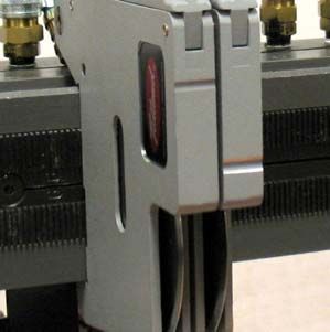
Mount Knifeholder to Guide Bar
1. Push the clamp lever back and hook the knifeholder under the guide bar.
2. Rotate the knifeholder up toward the guide bar and push the clamp forward to lock.
CLAMP LEVER
ECCENTRIC
GUIDE BAR
3. To adjust clamp lever tension on the guide bar:
a. Loosen the eccentric lock screw.
b. Adjust the eccentric as needed, checking
the clamp lever for secure fit. ECCENTRIC
ECCENTRIC
c. Tighten the lock screw. LOCK SCREW
4. Ensure that the knifeholder is square on the
guide bar.
Using High and Low Ribs
• For spacing in 0.04" (1 mm) increments, use alternate High and Low rib knifeholders.
Contact Tidland Customer Service for assistance. 1-800-426-1000
• You will need to install the index rack on your guide bar to achieve this spacing. The guide bar is
tapped for pre-drilled holes in the index rack.
• The index rack also ensures that the knifeholder is mounted in a true vertical alignment.
• The groove on the front of the knifeholder indicates a high or low ribbed unit.
HIGH/LOW RIB
INDICATORS
Tidland Precision Lock (12 mm) Knifeholder 8 553334 800.426.1000
Installation, Operation and Maintenance Rev D 08/11 www.maxcessintl.comOPERATION
The Precision Lock Crush Knifeholder is designed for total web separation slitting, rather than scoring
or partial depth slitting. Perforating wheels can be used; contact Tidland Customer Service for
assistance. 1-800-426-1000.
NOTICE Intermittent slitting (rapid on-off-on-off) to achieve perforation is not recommended.
Operating the Knifeholder
1. Do not permit the blade to "slam" onto the anvil.
Tidland recommends installing an air flow control valve
to control the down stroke speed.
2. Using a new blade, determine the initial run pressure. This is the
minimum air pressure required to reliably slit the web product.
3. As speeds increase, air pressure may need to be increased.
4. Replace dull blades, rather than continue to increase the air
pressure.
5. After changing blades, return the air pressure to the initial run
pressure before resuming operation.
Anvil Roll Specifications (Recommended)
• Drive the anvil roll at web speed.
• Minimize the runout of the anvil roll. A suggested maximum total indicated runout (t.i.r.) is:
1/(rpm/50) = t.i.r. (expressed as mm).
• Harden the anvil roll surface to 62-64 RC.
• Larger anvil roll diameters have less deflection, fewer web guiding problems, and better slitter
blade life.
Tidland Precision Lock (12 mm) Knifeholder 9 553334 800.426.1000
Installation, Operation and Maintenance Rev D 08/11 www.maxcessintl.comPREVENTIVE MAINTENANCE
WARNING!
Hand hazard.
Blades are sharp.
Avoid injury—always wear stainless steel protective gloves when handling blades.
General
• Keep knifeholder blades sharp and balanced. See pages 12-13 for blade finishing specifications.
• Do not use oil lubricants in knifeholder
Daily
• Clean all knife blades using compressed air or isopropyl alcohol.
• Check air pressure: Clean, dry, non-lubricated air is essential for optimal performance of your
knifeholders.
• Keep the knifeholders clean and dry.
Note: DO NOT immerse knifeholders in solvents. Wipe the outer surfaces with a clean rag.
• Check knifeholder air pressure.
Weekly
• Check for air leaks at all fittings.
Yearly
• Proper lubrication is critical to knifeholder performance and life cycle of parts.
• Disassemble knifeholder and inspect all wear parts.
• Lubricate as indicated on page 11.
• In harsh slitting environments, Tidland recommends more frequent inspection and maintenance.
Guide Bar Maintenance
• Keep the guide bar clean. Periodically wipe the guide bar with a clean, dry cloth.
• Clean index rack, if installed, with compressed air.
Clamp Lever Assembly
Keep the clamp lever free of debris buildup. Disassemble if necessary and clean the parts.
1. Remove the eccentric lock screw,
the eccentric and the clamp lever.
2. The clamp block/cam roller
assembly is under slight spring
tension. Drive the roll pin out of
the knifeholder body and pull the SPRING
assembly out; use care to retain
the spring. (Recommend arbor
press and 4 mm dia rod to press ROLL PIN
out the pin.)
3. When reinstalling the clamp block ECCENTRIC
o
assembly, insert the spring into LOCK CLAMP BLOCK/CAM ROLLER
the clamp block, and then press SCREW
the assembly back into the
ECCENTRIC
knifeholder.
4. Reinstall the roll pin. n CLAMP LEVER
5. Reinstall the clamp lever and
adjust the tension. (See page 3.)
Tidland Precision Lock (12 mm) Knifeholder 10 553334 800.426.1000
Installation, Operation and Maintenance Rev D 08/11 www.maxcessintl.comGENERAL MAINTENANCE
Knifeholder Disassembly
Turn off the air supply to the knifeholders to retract the knife blades before removing knifeholders from
the guide bar.
1. To avoid injury during disassembly, remove the knife blade first. Using slip-joint pliers, gently grasp
the edge of the blade and pull it out of the knifeholder body. See pages 12-13 for knife blade
maintenance information.
2. Remove the two Phillips head screws from the knifeholder body to remove the cap;
there is a small amount of spring tension in the cap.
3. Carefully pull the cap off of the knifeholder body; note the two springs in the knifeholder body.
4. Remove the springs.
5. Remove the piston/fork assembly and the piston seal. If the piston seal is stuck inside the cap,
apply very low air pressure to the air hose fitting to release the seal. (Note the orientation of the
piston seal for reassembly; its flat side sits on top of the piston for with the cavity pointing up into the
knifeholder cap.)
6. Check the seal for cracks or wear; replace if necessary. Before reinstalling the seal, apply Parker
Super O-Lube o-ring lubricant to its outer surfaces.
7. Reassemble the knifeholder and reinstall the knife blade.
8. If installing a new knife blade, ensure that the air pressure is returned to initial run pressure before
resuming operation. (See page 9.)
See page 10 for Clamp Lever disassembly.
KNIFE BLADE W/
BEARING AND AXLE
PHILLIPS HEAD
SCREW (2 PLCS)
SPRING (2 PLCS)
PISTON/FORK ASSY
AND PISTON SEAL
KNIFEHOLDER CAP
CLAMP LEVER ASSEMBLY
AIR SUPPLY FITTING
Tidland Precision Lock (12 mm) Knifeholder 11 553334 800.426.1000
Installation, Operation and Maintenance Rev D 08/11 www.maxcessintl.comGENERAL MAINTENANCE
Knife Blade
WARNING!
Hand hazard.
Blades are sharp.
Avoid injury—always wear stainless steel protective gloves when handling blades.
• Worn blades may become chipped and sharp, especially if high air pressures and small blade tip
radii have been used.
• Stop machine and disconnect knifeholder from air supply before releasing clamp.
Removing and Reinstalling the Knife Blade
1. Using pliers, pull the blade/bearing/axle assembly out of the knifeholder body.
2. Inspect the bearing for wear; replace if necessary. (The bearing and/or axle may need to be
pressed out of the blade.)
3. With the bearing and axle centered axially in the blade, push the blade into the knifeholder,
making sure the axle is securely captured by the forks. (See assembly illustration on page 14.)
NOTICE Do not use replacement blades larger than 3.03" (77 mm).
BLADE
BEARING
AXLE
Blade Regrinding
1. Remove the bearing before regrinding.
2. Regrind the blade to the original angle. Use a grinding coolant.
3. Re-radius the tip and polish smoothly.
See Blade Profile Chart on page 13.
Tidland Precision Lock (12 mm) Knifeholder 12 553334 800.426.1000
Installation, Operation and Maintenance Rev D 08/11 www.maxcessintl.comGENERAL MAINTENANCE
Crush Slitting Blade Profiles
These blade profiles should be viewed as reference points in determining the optimal profile for any
given material.
• Smaller tip radii and acute angles result in rapid tip fracture and anvil roll grooving.
• Larger tip radii and included angles require more force to slit.
• To reduce chipping and rapid dulling of blades, it is important to remove burred edges from
resharpened blades.
• Make sure to grind the blade edge smooth to avoid dust formation during the slitting process.
Tidland Precision Lock (12 mm) Knifeholder 13 553334 800.426.1000
Installation, Operation and Maintenance Rev D 08/11 www.maxcessintl.comASSEMBLY DIAGRAM AND PARTS LIST
Knifeholder Part No.
High Rib Model 568864
Low Rib Model 568865
2
12
15 16
13
14
20
5
1
3
4 10
19
18
9
7* 17
11*
6 8*
Item Description Qty Part No. Item Description Qty Part No.
1 Body 1 * 12 Knife Blade 1
2 Cap 1 * 52100 Steel .005" tip radius 568119
3 Piston/Fork Assembly 1 * 52100 Steel .002" tip radius *** 706504
4 Piston Seal 1 * D2 Steel .005" tip radius 568120
5 Return Springs (Cap) 2 709631 13 Bearing 1 567555
6 Clamp Lever 1 682076 14 Axle 1 568863
7 Clamp Block 1 ** 15 Air Tube and Fitting 1 587022
8 Cam Roller 1 ** 16 Quick Disconnect (opt.) 1 131029
9 Eccentric 1 682079 17 Guide Bar 1 567552
10 Pivot Pin 1 709632 18 Index Rack **** 1 566997
11 Cam Roller Pin 1 ** 19 Spring (Cam Block Assembly) 1 682075
20 Phillips Head (4 mm) 3 stock
* Replaced as complete assembly
** Items 7, 8, and 11 are sold as assembly Part No. 682077
*** Special order
**** Includes 5 mm socket head cap screws for mounting
Tidland Precision Lock (12 mm) Knifeholder 14 553334 800.426.1000
Installation, Operation and Maintenance Rev D 08/11 www.maxcessintl.comTROUBLESHOOTING
Knifeholder Performance
Problem Possible Cause Recommended Solution
Knifeholder doesn't retract No lube on piston/fork Disassemble knifeholder and apply thin film of
assembly 4700-4702 MONOLEC® to piston fork (p 11).
Air not exhausted from
Exhaust all air from manifold.
manifold
Remove knife blade from knifeholder and
Contamination between
clean. Use compressed air to blow and dust
knifeholder and blade
and build up from inside the body.
Disassemble knifeholder and check for broken
Broken spring
or missing springs: item 5, p. 14
Blade does not extend Ensure proper air supply (p. 4).
Air leak
Check all air fittings for leaks.
Remove knife blade from knifeholder and
Jammed due to buildup clean. Use compressed air to blow dust and
debris from inside the body.
Blade does not rotate easily Bearing and axle not Remove knife blade from knifeholder body;
centered on blade center the bearing and axle axially in the blade.
Knifeholder loose on guide Eccentric not adjusted Adjust the eccentric as needed for a tight fit on
bar correctly the guide bar (p. 8).
Slit Quality
Slit edge is fuzzy Dull blade Sharpen or replace knife blade (p. 12).
Knifeholder loose on Adjust the eccentric as needed for a tight fit on
the guide bar the guide bar (p. 8).
Incorrect setback Check geometry (p. 6).
May require roll regrind or resize.
Driven anvil run-out
See specs on page 9.
Slit line is not straight Knifeholder loose on Adjust the eccentric as needed for a tight fit on
the guide bar the guide bar (p. 8).
Worn bearing Replace bearing (p. 12).
Web tears, splits or breaks Dull blade Sharpen or replace knife blade (p. 12).
Web tension is too high Reduce tension.
Short blade life Blade profile incorrect for
See blade profile chart on page 13.
web material
Blade slamming onto Tidland recommends installing an air flow
hardened anvil control valve to control the down stroke speed.
Web bunches in front of Anvil roll speed does not
Adjust operating speeds.
knife blade match web speed
Check bearing and axle in blade; they should
Blade not rotating freely
be centered in the knife blade.
Tidland Precision Lock (12 mm) Knifeholder 15 553334 800.426.1000
Installation, Operation and Maintenance Rev D 08/11 www.maxcessintl.comTIDLAND ANVIL ROLLS
If your anvil roll is equipped with adjustable hardened anvil sleeves, you may need to shift the position
of the anvil sleeves to achieve a new cutting surface when a groove has worn in the anvil from
prolonged slitting,
Moving the Anvil Sleeves
WARNING!
Hand hazard.
Blades are sharp.
Avoid injury—wear stainless steel protective gloves when handling blades.
1. Stop the slitting operation and retract the knifeholder blades. You do not need to remove the anvil
roll from the system.
2. Unbend the tabs on lockwashers, if installed*, at each end of the anvil roll and loosen the locknuts.
3. Turn the locknuts at both ends to move the sleeve(s) to new location.
4. At one end of the shaft, align the notch in the nut with a lockwasher tab, if installed, and rebend
the tab to lock in place.
5. Tighten the locknut on the other end, pushing the sleeves toward the first nut. Align the notch in
the remaining nut with a lockwasher tab and rebend the tab to lock in place. Once locked, sleeves
should not move axially.
6. Resume slitting operation.
* If your anvil roll is equipped with the dual locknut design, loosen the two locknuts that are locked
together. After moving the anvil sleeves, tighten the nuts against each other to secure the sleeves in
place on the anvil roll.
Removing the Anvil Sleeves for Replacement
1. Stop shaft rotation.
2. Complete your company lock-out procedures to lock-out system power.
3. To help ensure safety and avoid damage to the system, provide alternative support for the anvil
roll before removing the bearing cover plate, if installed, and bearing.
4. When slitter shaft is properly supported, remove bearing.
5. With anvil roll still supported, remove locknuts, washers, and sleeves through the opening in the
side frame.
Optional: Remove the anvil roll from the slitter sytem.
1. Loosen the set screws at the other end of the anvil roll and slide it out of the opening in the side
frame.
2. Transport the anvil roll to a secure workbench.
All rights reserved. No part of this publication may be reproduced, transmitted, transcribed,
or translated into any language in any form by any means without the written permission of Tidland.
NORTH AMERICA EUROPE CHINA KOREA, TAIWAN,
Toll Free 800.639.3433 Tel +49.6195.7002.0 Tel +86.756.881.98398 AND SE ASIA
Tel +1.405.755.1600 Fax +49.6195.7002.933 Fax +86.756.881.9393 Tel +65.9620.3883
Fax +1.405.755.8425 sales@maxcess.eu sales@maxcessintl.com.cn Fax +65.6235.4818
sales@maxcessintl.com www.maxcess.eu www.maxcessintl.com.cn asia@maxcessintl.com
www.maxcessintl.com
SOUTH AMERICA INDIA JAPAN
Tel +55.11.3959.0990 Tel +91.22.27602633 Tel +81.43.421.1622
Fax +55.11.3856.0990 Fax +91.22.27602634 Fax +81.43.421.2895
southamerica@maxcessintl.com india@maxcessintl.com japan@maxcessintl.com
www.maxcessintl.com.br www.maxcess.in www.maxcess.jp © 2011 MaxcessYou can also read