PROCEEDINGS OF SPIE Coherent detection of the light backscattered by an optical surface
←
→
Page content transcription
If your browser does not render page correctly, please read the page content below
PROCEEDINGS OF SPIE
       SPIEDigitalLibrary.org/conference-proceedings-of-spie

                   Coherent detection of the light
                   backscattered by an optical surface

                   Khan, Imran, Lequime, Michel, Zerrad, Myriam, Amra,
                   Claude

                                  Imran Khan, Michel Lequime, Myriam Zerrad, Claude Amra, "Coherent
                                  detection of the light backscattered by an optical surface," Proc. SPIE 11852,
                                  International Conference on Space Optics — ICSO 2020, 1185241 (11 June
                                  2021); doi: 10.1117/12.2599635

                                  Event: International Conference on Space Optics — ICSO 2021, 2021, Online
                                  Only

Downloaded From: https://www.spiedigitallibrary.org/conference-proceedings-of-spie on 30 Aug 2021 Terms of Use: https://www.spiedigitallibrary.org/terms-of-use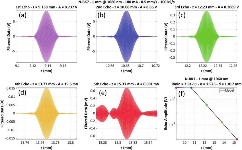
International Conference on Space Optics—ICSO 2020
                Virtual Conference
                30 March–2 April 2021

                                                                             Edited by Bruno Cugny, Zoran Sodnik, and Nikos Karafolas

              Coherent detection of the light backscattered by an optical surface

                                      International Conference on Space Optics — ICSO 2020, edited by Bruno Cugny, Zoran Sodnik,
                                                Nikos Karafolas, Proc. of SPIE Vol. 11852, 1185241 · © 2021 ESA and CNES
                                                          CCC code: 0277-786X/21/$21 · doi: 10.1117/12.2599635

                                                                        Proc. of SPIE Vol. 11852 1185241-1
Downloaded From: https://www.spiedigitallibrary.org/conference-proceedings-of-spie on 30 Aug 2021
Terms of Use: https://www.spiedigitallibrary.org/terms-of-use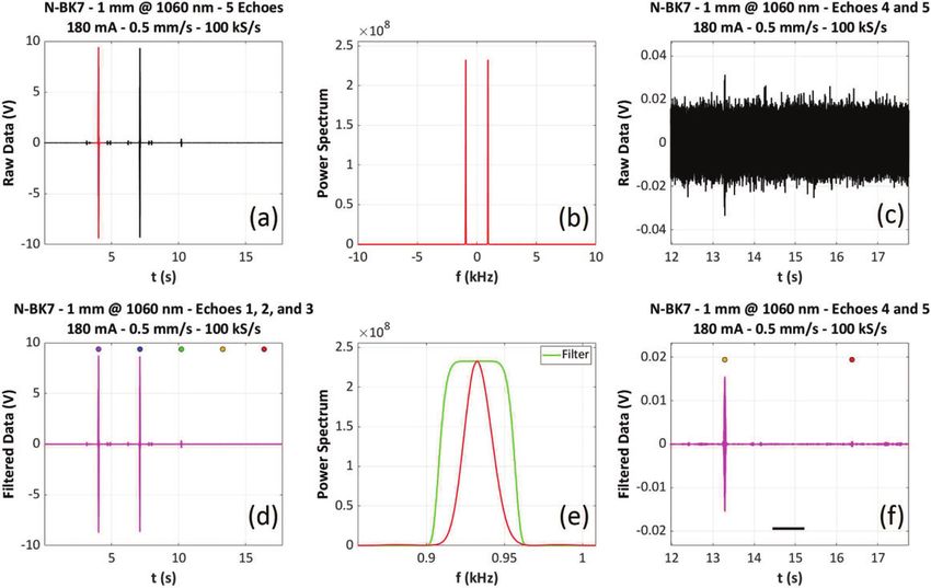
ICSO 2020                                                                                    Virtual Conference
                   International Conference on Space Optics                                                  30 March-2 April 2021

                 Coherent Detection of the Light Backscattered by an Optical
                                           Surface
                                        Imran Khan, Michel Lequime, Myriam Zerrad, and Claude Amra
                           Aix Marseille Univ, CNRS, Centrale Marseille, Institut Fresnel, Marseille, France

                                                                                 ABSTRACT
                We measured very low light power backscattered by optical surfaces using low coherence interferometry. The
                backscattered light can indeed be a critical noise source for interferometric gravitational wave detectors such
                as LISA, the laser interferometer space antenna developed by ESA, with the support of NASA and European
                national space agencies. We present the preliminary measurement results of light backscattered from a silver
                mirror and a bare N-BK7 window 1 mm thick using a superluminescent diode centered at 1060 nm as broadband
                light source. The use of low coherence interferometry allows light backscattered by both sides of the N-BK7
                window to be recorded independently with a noise floor of around -110 dB.
                Keywords: Scattered Light, Low Coherence Interferometry, Gravitational Waves Detector

                                                                         1. INTRODUCTION
                With the first direct detection of Gravitational Waves (GW) by LIGO and Virgo scientific collaboration [1] in
                September 2015, a new observational astronomy window on the universe has been established. And the network
                of LIGO [2] and Virgo [3] detectors have reported numerous number of GW events consisting of binary black hole
                systems, a neutron star and black hole system, and rotating neutron star system [4, 5, 6] with the heaviest GW
                event detected so far of total mass of 150 M◦ [7]. The current generation of GW detectors and future planned
                third generation (Einstein Telescope, ET) will further improve the strain sensitivity in the detection bandwidth
                of 1 Hz to 10 kHz, thus increasing the detection efficiency of GW sources of mass in the range of stellar mass
                black holes (few 100’s of M◦ ), rotating neutron stars and and asymmetric supernovae sources.
                    However, to explore the GW sources emitting at low frequency in the bandwidth (0.1 mHz to 1 Hz), that
                correspond to astrophysical sources such as super massive black holes and dense stars captured by super massive
                black holes, an interferometer with very long arms is required. Due to the seismic activity of the Earth such large
                scale interferometer cannot be built on earth and thus, the outer space becomes the ultimate choice. One such
                large scale interferometer, named as Laser Interferometer Space Antenna (LISA) that will have interferometer
                arm lengths on the order of millions of kilometers was proposed by ESA with the help of NASA and European
                national space agencies and is currently under the initial phase of development [8, 9, 10].
                    For all these GW interferometric instruments, parasitic light [10, 11, 12, 13, 14] is a critical noise source
                because, as a first order approximation, it can induce phase measurement errors depending on the relative
                amplitude of these parasitic optical fields. By way of example, this means that phase uncertainties of the order
                of a few microradians can be induced by ultra-weak retroreflected or back-scattered light, the relative power of
                which is about 10−12 . The availability of a characterization equipment capable of detecting such ultra-low light
                power is therefore a key point of the development of this new generation of GW detectors.
                    Further author information: (Send correspondence to Imran Khan and Michel Lequime)
                    Imran Khan: E-mail: imran.khan@fresnel.fr,
                    Michel Lequime: E-mail: michel.lequime@fresnel.fr

                                                                        Proc. of SPIE Vol. 11852 1185241-2
Downloaded From: https://www.spiedigitallibrary.org/conference-proceedings-of-spie on 30 Aug 2021
Terms of Use: https://www.spiedigitallibrary.org/terms-of-use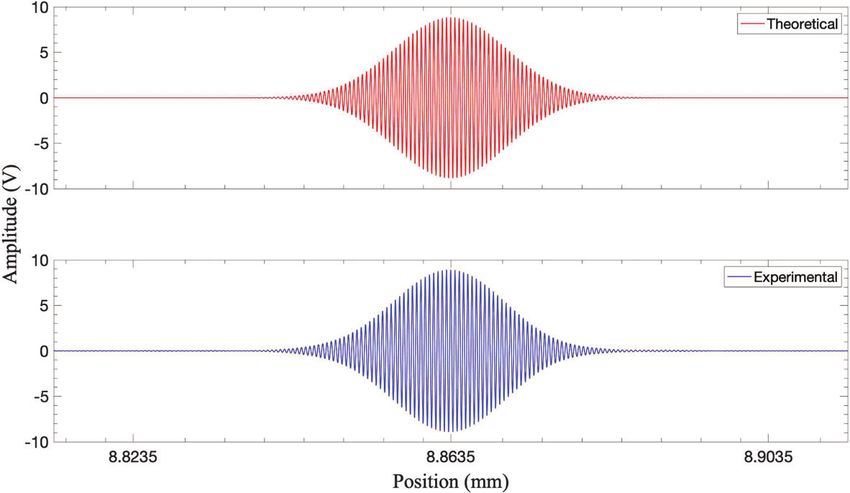
ICSO 2020                                                                                    Virtual Conference
                   International Conference on Space Optics                                                  30 March-2 April 2021

                                                            2. THEORETICAL BACKGROUND
                Low coherence interferometry is a powerful tool in precise measurements of surface details of samples, and in
                particular the characterization of samples with multiple surfaces [15, 16]. The basic principle consists of a
                broadband light beam that is split into the two arms of a Michelson interferometer i.e, the reference and the
                sample arms, and the resulting signal due to the mixing of light backreflected by the two arms is detected using
                a photodiode.
                The output signal of the interferometer depends on the amount of light power back-reflected by each of the two
                arms (with surface reflectivities Rr and Rs ) and the optical path difference Δ = 2(zr − zs ) between these two
                arms. Mathematically, the output signal for a single optical interface is given by
                                                                                        2

                                             S(zr , zs ) = S0 Rr + Rs + 2 Rr Rs e−(πδσΔ) cos k0 Δ                           (1)

                 where S0 is the spectrally integrated power of the source, here assumed to be of Gaussian shape, k0 the central

                Figure 1: Theoretical versus experimentally measured low coherence interferometric signal for a source at
                λ0 =1060 nm with optical 3 dB bandwidth of around 70 nm.

                wave vector, and δσ the source bandwidth in wavenumber. Consequently, the signal S is only modulated around
                zero optical path difference (OPD) and over a characteristic distance lc named the coherence length of the source
                and defined by
                                                                   1      2 ln(2) λ20
                                                             lc =      =                                                     (2)
                                                                  πδσ        π     Δλ
                where λ0 is the central wavelength of the source and Δλ its spectral full width at half maximum (FWHM).
                Figure 1 shows a comparison between the theoretical shape of the modulated part of the interferometric signal
                (λ0 = 1060 nm, Δλ =70 nm) and the one experimentally recorded. For a multiple reflections sample, the low
                coherence interferometric signal is a function of the length of the scanned reference arm and given by

                                                    N
                                                               N
                                                                                             2
                                   S(zr ) = S0 Rr +   Rs,m + 2     Rr Rs,m e−[2πδσ(zr −zs,m )] cos 2k0 (zr − zs,m )              (3)
                                                           m=1                n=1

                where m is an integer that defines the order of the back-reflected signal. The scan of the reference arm allows
                the successive reflections (echoes) to be independently recorded and quantified. As an example, if a 1-mm thick
                N-BK7 window is installed in the sample arm of the Michelson interferometer at zero angle of incidence, we
                are capable to successively record the reflection on the front face (Rs,1 = 0.04, zr = zs ), the reflection on the
                rear face (Rs,2 = 0.037, zr = zs + nd, d = 1 mm and n = 1.5054), the first multiple reflection within the
                window (Rs,3 = 6.2 × 10⁻⁵ , zr = zs + 2nd), the second multiple reflection within the same window (Rs,4 =
                1.02 × 10⁻⁷ , zr = zs + 3nd), and so on [Rs,m = (1 − R)2 R(2m−3) , zr = zs + (m − 1)nd, m ≥ 2] up to the limit
                defined by the noise floor of the set-up.

                                                                        Proc. of SPIE Vol. 11852 1185241-3
Downloaded From: https://www.spiedigitallibrary.org/conference-proceedings-of-spie on 30 Aug 2021
Terms of Use: https://www.spiedigitallibrary.org/terms-of-use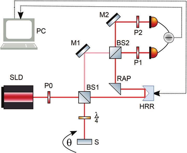
ICSO 2020 Virtual Conference
International Conference on Space Optics 30 March-2 April 2021
3. EXPERIMENTAL SETUP
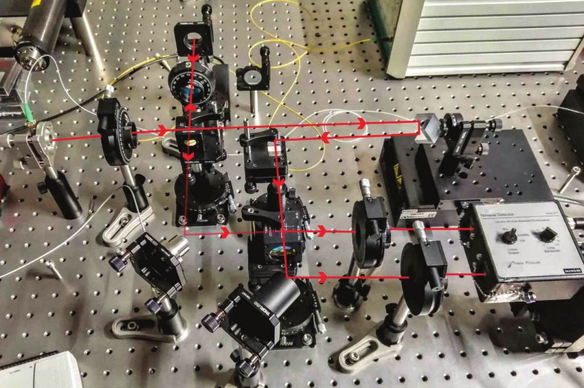
The optical layout of the experiment is shown in Figure 2a and a picture of the implemented bench is shown
in Figure 2b. Our experiment consists of a 60 mW pigtailed superluminescent diode (SLD) with a central
wavelength of 1060 nm and FWHM bandwidth of 70 nm. The pigtail consists of a Corning HI 780 single mode
fiber whose output is located in the focal plane of a reflective collimator with an effective focal length of 7 mm.
This assembly provides a Gaussian collimated light beam with a waist diameter around 2 mm. The input optical
beam is split using a polarizing cube beam splitter (BS1) into the signal and reference arms of the interferometer
and the split ratio can be adjusted by changing the orientation of the linear polarizer P0. The beam reflected
by the polarizing beam splitter (S polarization) corresponds to the sample arm. It crosses a quarter wave plate
with axis at 45 degrees and illuminates the sample whose tilt angle is θ. The light back-reflected (θ = 0) or
back-scattered (θ > 0) by the sample is transformed in a P-polarized beam by the back-crossing of the quarter
wave plate, then is transmitted by the polarizing beam splitter.
The beam transmitted by the polarizing beam splitter (P polarization) corresponds to the reference arm
(a) Layout of the optical bench. (b) The implemented laboratory bench.
Figure 2: The experiment.
and is reflected by a hollow retroreflector (HRR). The HRR along with a right angle prism (RAP) allows the
reflected beam to be decoupled from the incidence path such that it can be mixed with the signal. The hollow
retroreflector is mounted on a Newport XMS-100 S motorized linear translation stage, while the sample is
mounted on a Thorlabs PRMTZ8 motorized rotation. The sample beam and the reference beam are mixed on
a non-polarizing beam splitter (BS2) and detected using a balanced receiver including two InGaAs photodiodes
(Newport Nirvana 2017 model). Two linear polarizers (P1 and P2) are used to optimize the balance between
the DC part of the currents provided by each photodetector. The output channel of the balanced detection is
acquired using National Instruments (NI) data acquisition (DAQ) module USB-6212 (16 bits, 100 kSamples/s)
and post processed numerically.
4. RESULTS AND DISCUSSION
We measured light backscattered by two different samples i.e, 1 mm thick N-BK7 optical window and a Silver
mirror. In order to demonstrate the sensitivity of the experimental set-up, we first measured the light backre-
flected from a 1 mm thick N-BK7 window at zero AOI.
The reference arm is scanned at a constant velocity of 0.5 mm/s, which generates a carrier frequency of around
935 Hz in the signal resulting from the differential amplification of the photodiode outputs. A bandpass filtering
is implemented on this acquired signal (bandwidth 50 Hz) and allows the noise level to be drastically reduced.
A key point of this balanced detection scheme is the necessity to avoid any saturation of the two photodetectors.
This implies to limit the overall detected power (DC plus AC parts) below 0.5 mW. For instance, in the case of
the detection of multiple reflections on a N-BK7 window, we operated the SLD source below 2 mW of continuous
power (driving current 180 mA) to meet this condition.
Proc. of SPIE Vol. 11852 1185241-4
Downloaded From: https://www.spiedigitallibrary.org/conference-proceedings-of-spie on 30 Aug 2021
Terms of Use: https://www.spiedigitallibrary.org/terms-of-use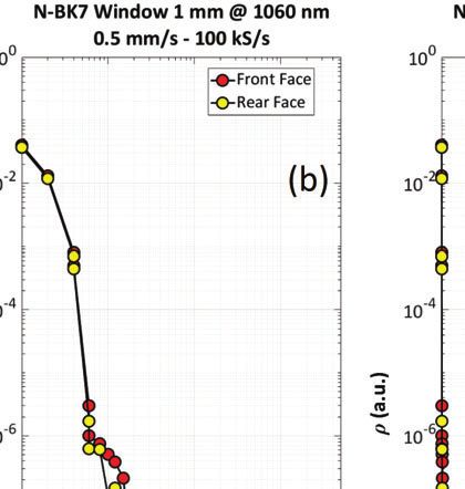
ICSO 2020                                                                                    Virtual Conference
                   International Conference on Space Optics                                                  30 March-2 April 2021

                       Figure 3: Backreflected light measured from 1 mm thick N-BK7 window (see text for more details).

                Figure 4: 4(a) to 4(e): Enlarged views of the interferograms corresponding to the five first reflections (R1 to R5)
                on a 1-mm thick N-BK7 window ; in each drawing title, A is the maximum amplitude of the corresponding echo
                and z is the position of this maximum - 4(f): comparison between the experimental results and the amplitude
                and position data resulting from a modelling.

                4.1 Backreflected light from 1 mm thick N-BK7 window
                The interferogram recorded from a 1 mm thick N-BK7 window is shown in Figures 3 and 4. Figure 3(a) shows the
                raw signal recorded during a continuous scan of the reference arm approximately 10 mm long, while Figure 3(c)
                shows an enlarged view of the same signal corresponding to the last 8 seconds of the acquisition. Applying a fast
                Fourier transform (FFT) to the red part of this recorded signal (first echo) allows the intrinsic power spectrum
                of an echo to be calculated [Figures 3(b) and 3(e), red curves] and the characteristics to the frequency band-pass
                filter [Figure 3(e), green curve] to be determined (central frequency, bandwidth). This band-pass filtering is
                applied to the Fourier transform of the raw signal and an inverse FFT allows the time dependence of the filtered
                signal to be reconstructed [see Figures 3(d) and 3(f), magenta curves). One can see the big improvement provided
                by this band-pass filtering by comparing Figures 3(c) and 3(f). Moreover, on Figures 3(d) and 3(f), colored dots
                are used to indicate the theoretical position of the center of the interferograms corresponding to the multiple
                reflections on the N-BK7 window: the agreement with the experimental results is really excellent.
                Figures 4(a) to 4(e) shows an enlarged view of the interferograms corresponding to the first five echoes recorded
                on the 1-mm thick N-BK7 window (filtered data). One can note the very nice and almost identical shape of the

                                                                        Proc. of SPIE Vol. 11852 1185241-5
Downloaded From: https://www.spiedigitallibrary.org/conference-proceedings-of-spie on 30 Aug 2021
Terms of Use: https://www.spiedigitallibrary.org/terms-of-use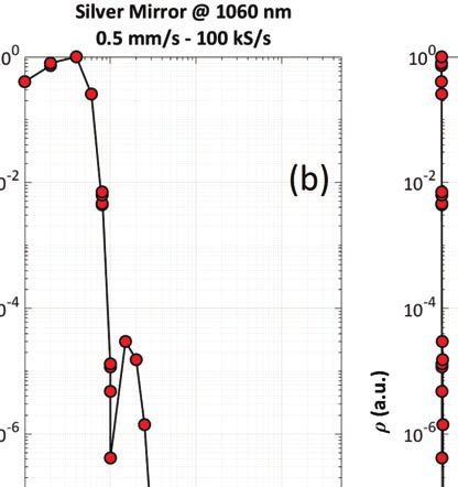
ICSO 2020                                                                                    Virtual Conference
                   International Conference on Space Optics                                                  30 March-2 April 2021

                first four echoes, and the presence of some spurious contributions in that of the fifth echo: this is induced by the
                low signal to noise ratio obtained when the corresponding coefficient of reflection is as low as 2.6 × 10⁻¹⁰ . Figure
                4(f) shows a comparison between the experimental amplitude and position of the first five echoes (colored dots)
                and the result of a theoretical modelling (black curve): one can note the impressive quality of the agreement.
                Using all these results allows the minimal value of the back-reflected coefficient (signal equal to 3 times the
                standard deviation of the noise) to be determined, i.e. 3.9 × 10⁻¹¹ (-104 dB).

                4.2 Backscattered light from a Silver mirror

                Figure 5: Back-scattered light interferograms recorded at different angles of incidence from a silver mirror (raw
                data) - Only a few interferograms are shown for the sake of simplicity.

                                      Figure 6: Same recordings as shown in Figure 5, but after frequency filtering.

                    In order to demonstrate the ability of the set-up to efficiently detect the light back-scattered by an optical
                surface, we first used a silver mirror as trial sample (reflection coefficient about 95%). Indeed, the amount of light
                scattered at low tilt angle is proportional to the reflection coefficient of the sample. As the coefficient of reflection
                of the silver mirror is very high, the recording of the interferogram obtained at zero AOI is achieved using a very
                low driving current (I=110 mA). Then we rotated the sample in steps and recorded the interferograms at full
                source power (I=1000 mA). The results are shown in Figures 5 (raw data) and 6 (filtered data). In Figure 7 (a),
                one can see the change in position of the backscattered light interferogram versus the AOI in (blue dots), as well

                                                                        Proc. of SPIE Vol. 11852 1185241-6
Downloaded From: https://www.spiedigitallibrary.org/conference-proceedings-of-spie on 30 Aug 2021
Terms of Use: https://www.spiedigitallibrary.org/terms-of-use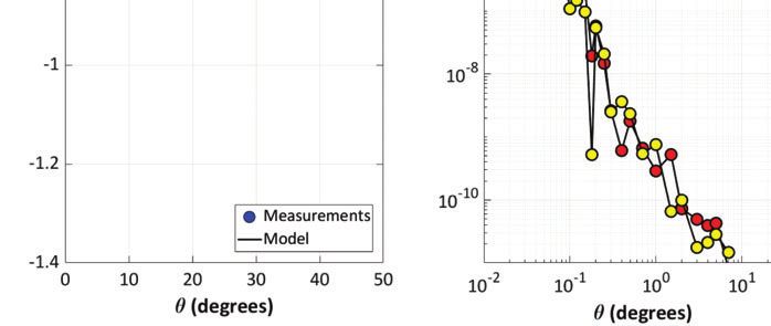
ICSO 2020                                                                                    Virtual Conference
                   International Conference on Space Optics                                                  30 March-2 April 2021

                Figure 7: Backscattered light measured from Silver mirror at different AOIs. Figure 7(a) change in interferogram
                position versus the AOI, Figure 7(b) amplitude of the backscattered light versus AOI (log-log scale) and Figure
                7(c) amplitude of the backscattered light versus AOI (log-linear scale).

                as the result of a modelling (black curve) taking into account an offset r between the front face of the sample
                and the axis of rotation. Such an offset r yields a change Δz in the interferogram position for the changing AOI
                described by the following relationship
                                                                           r
                                                                  Δz =         −r                                               (4)
                                                                         cos θ
                Figures 7(b) and 7(c) show the variation of the amount of light backscattered by the silver mirror versus the tilt
                angle of the sample (θ). The data shown in these two curves are identical, the only difference is the use of a
                log scale for the angle of incidence in Figure 7(b) instead of a linear scale for the same quantity in Figure 7(c).
                This allows to have a better view of the steep variation of this backscattered light below 0.5 degree. The amount
                of backscattered light is detected by the experimental set-up up to 50 degrees AOI (coefficient of reflection of
                around a few 10−11 ).

                4.3 Backscattered light from 1 mm thick N-BK7 window

                Figure 8: Back-scattered light interferograms recorded at different angles of incidence from a bare N-BK7
                window (raw data) - Only a few interferograms are shown for the sake of simplicity.

                                                                        Proc. of SPIE Vol. 11852 1185241-7
Downloaded From: https://www.spiedigitallibrary.org/conference-proceedings-of-spie on 30 Aug 2021
Terms of Use: https://www.spiedigitallibrary.org/terms-of-use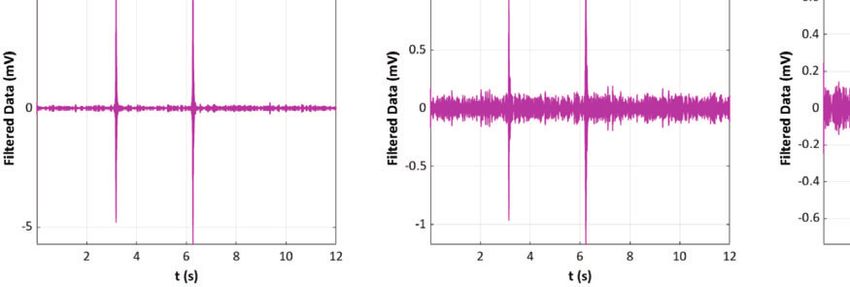
ICSO 2020                                                                                    Virtual Conference
                   International Conference on Space Optics                                                  30 March-2 April 2021

                                      Figure 9: Same recordings as shown in Figure 8, but after frequency filtering.

                Figure 10: Backscattered light measured from N-BK7 window at different AOIs. Figure 10(a) change in
                interferogram position versus the AOI, Figure 10(b) amplitude of the backscattered light versus AOI (log-log
                scale) and Figure 10(c) amplitude of the backscattered light versus AOI (log-linear scale).

                    And finally, we measured light backscattered from a 1 mm thick N-BK7 window. Compared to the Silver
                mirror, the measurement is more demanding, because in this case the coefficient of reflection is only 4 %. Figures
                8, 9, and 10 show the experimental results obtained on this bare window, using the same approach as used for
                the silver mirror in Figures 5, 6 and 7. One can note that the method allows the light backscattered by the front
                face and the rear face to be independently recorded. This property is very important for stray light metrology
                application because the contributions of different surfaces can be separated. One can note that the maximum
                AOI is here equal to 8 degrees as compared to 50 degrees for Silver mirror and this is due to the reduction of
                coefficient of reflection from 95% to 4%.

                                                                            5. CONCLUSION
                We presented the preliminary results of measurement of light backscattered by a N-BK7 window and a Silver
                mirror using low coherence interferometry. To the best of our knowledge, the simultaneous measurement of the
                light backscattered from the front and rear faces of an optical window has been achieved for the very first time.
                The noise floor of our method is about 10−11 in terms of coefficient of reflection, and some changes in the set-up
                are currently underway to improve this performance up to 10−13 .

                                                                        Proc. of SPIE Vol. 11852 1185241-8
Downloaded From: https://www.spiedigitallibrary.org/conference-proceedings-of-spie on 30 Aug 2021
Terms of Use: https://www.spiedigitallibrary.org/terms-of-use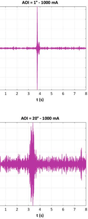
ICSO 2020                                                                                    Virtual Conference
                   International Conference on Space Optics                                                  30 March-2 April 2021

                                                                   6. ACKNOWLEDGEMENT
                This work is part of the StrayLight Working Group for the Laser Instrument Group of the LISA Consortium.
                The authors would like to thank the AMIdex Foundation, Aix Marseille University and the French National
                Space Center (CNES) for funding the research activity.

                                                                                  References
                  [1] The LIGO and Virgo scientific collaboration, “Observation of gravitational waves from a binary black hole
                      merger,” Phys. Rev. Lett. 116, 061102 (Feb 2016).
                  [2] A. Abramovici et al., “Ligo: The laser interferometer gravitational-wave observatory,” Science 256(5055),
                      325–333 (1992).
                  [3] F. Acernese et al., “Status of virgo detector,” Classical and Quantum Gravity 24, S381–S388 (sep 2007).
                  [4] R. Abbott et al. (LIGO Scientific Collaboration and Virgo Collaboration), “Population Properties of
                      Compact Objects from the Second LIGO-Virgo Gravitational-Wave Transient Catalog,” arXiv e-prints ,
                      arXiv:2010.14533 (Oct. 2020).
                  [5] R. Abbott et al., “GWTC-2: Compact Binary Coalescences Observed by LIGO and Virgo During the First
                      Half of the Third Observing Run,” arXiv e-prints , arXiv:2010.14527 (Oct. 2020).
                  [6] R. Abbott et al., “Open data from the first and second observing runs of advanced ligo and advanced virgo,”
                      SoftwareX 13, 100658 (2021).
                  [7] R. Abbott et al. (LIGO Scientific Collaboration and Virgo Collaboration), “Gw190521: A binary black hole
                      merger with a total mass of 150 M ,” Phys. Rev. Lett. 125, 101102 (Sep 2020).
                  [8] G. Heinzel and C. Braxmaier et al., “Successful testing of the LISA technology package (LTP) interferometer
                      engineering model,” Classical and Quantum Gravity 22, S149–S154 (apr 2005).
                  [9] eLISA Consortium and P. Amaro Seoane et al., “The Gravitational Universe,” arXiv e-prints ,
                      arXiv:1305.5720 (May 2013).
                [10] S. Barke and Y. Wang et al., “Towards a gravitational wave observatory designer: sensitivity limits of
                     spaceborne detectors,” Classical and Quantum Gravity 32, 095004 (apr 2015).
                [11] S. Hild, Beyond the first Generation: Extending the Science Range of the Gravitational Wave Detector
                     GEO600, PhD thesis, Von der Fakultat fur Mathematik und Physik der Gottfried Wilhelm Leibniz Univer-
                     sitat Hannover zur Erlangung des Grades (2007).
                [12] D. J. Ottaway, P. Fritschel, and S. J. Waldman, “Impact of upconverted scattered light on advanced
                     interferometric gravitational wave detectors,” Opt. Express 20, 8329–8336 (Apr 2012).
                [13] M. Lequime, V. Khodnevych, M. Zerrad, M. Lintz, and C. Amra, “Coherent detection of the light back-
                     scattered by a rough surface,” in [Optical Interference Coatings Conference (OIC) 2019 ], Optical Interference
                     Coatings Conference (OIC) 2019 , TE.7, Optical Society of America (2019).
                [14] V. Khodnevych, S. Di Pace, J. Y. Vinet, N. Dinu-Jaeger, and M. Lintz, “Study of the coherent perturbation
                     of a Michelson interferometer due to the return from a scattering surface,” in [International Conference on
                     Space Optics — ICSO 2018 ], Society of Photo-Optical Instrumentation Engineers (SPIE) Conference
                     Series 11180, 111807T (July 2019).
                [15] K. Freischlad, “Sub-angstrom surface metrology with a virtual reference interferometer,” in [Interferometry
                     XVI: Techniques and Analysis], Schmit, J., Creath, K., Towers, C. E., and Burke, J., eds., 8493, 86 – 99,
                     International Society for Optics and Photonics, SPIE (2012).
                [16] M. Lequime and J. Lumeau, “Accurate determination of the optical performances of antireflective coatings
                     by low coherence reflectometry,” Appl. Opt. 46, 5635–5644 (Aug 2007).

                                                                        Proc. of SPIE Vol. 11852 1185241-9
Downloaded From: https://www.spiedigitallibrary.org/conference-proceedings-of-spie on 30 Aug 2021
Terms of Use: https://www.spiedigitallibrary.org/terms-of-use
You can also read