PREPARATION OF NIAL COATED NICKEL FOAM CATHODE FOR ALKALINE WATER ELECTROLYSIS USING ATMOSPHERIC PLASMA SPRAYING
←
→
Page content transcription
If your browser does not render page correctly, please read the page content below
Int. J. Electrochem. Sci., 15 (2020) 5916 – 5926, doi: 10.20964/2020.06.61

                                                                        International Journal of
                                                                        ELECTROCHEMICAL
                                                                                SCIENCE
                                                                              www.electrochemsci.org

Preparation of NiAl coated Nickel foam cathode for Alkaline
Water Electrolysis using Atmospheric Plasma Spraying
Xinghua Liang1,2,*, Xi Wu1,*, Xinqi Li1, Qixin Gai, Jie Mao2
1
  Guangxi Key Laboratory of Automobile Components and Vehicle Technology, Guangxi University
of Science & technology, Liuzhou 545000, China;
2
  Guangdong Institute of New Materials, National Engineering Laboratory for Modern Materials
Surface, Guangdong Academy of Science, Guangzhou 510651, China
*
 E-mail: 1442469834@qq.com

Received: 21 January 2020 / Accepted: 2 March 2020 / Published: 10 May 2020

Fuel cells have received close attention from countries around the world due to its high efficiency and
zero emissions. Hydrogen is one of the sources of chemical reactions in fuel cells. Generally, hydrogen
is made from electrolyzed water. Hydrogen energy has practical significance for modern society in
alleviating the energy crisis because of its high combustion heat value and wide sources. How to prepare
electrode materials with smaller hydrogen evolution overpotential and higher catalytic activity are the
key steps for industrialized electrolyzed water production of hydrogen. In this paper, a composite
electrode coated NiAl powder is prepared based on the foamed Ni by atmospheric plasma spraying
technology. Micromorphological characterization of uncoated foamed Ni electrode and NiAl coated
foamed Ni electrode by physical characterization such as XRD and SEM. The electrochemical activity
tests were performed on LSV, CA, CV, and EIS electrochemical test methods for uncoated foam Ni
electrodes and NiAl coated foam Ni electrode. It turned out that the Ni electrode with NiAl coated has a
positive shift of the hydrogen evolution potential by 0.08V compared with the uncoated Ni electrode,
and the electrochemical impedance is lower than that of the uncoated Ni electrode. NiAl-coated Ni
electrode have higher catalytic activity. Applying a functional coating on the electrode provides an
effective way to reduce the overpotential of alkaline water electrolysis for hydrogen production.

Keywords: Alkaline Water; Plasma Spraying; Electrocatalysis; Hydrogen Evolution Overpotential

1. INTRODUCTION

       Energy development and effective utilization are often used to assess the level of production
technology. The non-renewable energy sources like coal and natural gas has sounded the alarm for
resource depletion. The ensuing environmental pollution and ecological damage have become the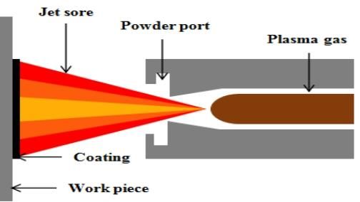
Int. J. Electrochem. Sci., Vol. 15, 2020                                                             5917

lifeblood of restricting global economic development [1-3]. Hydrogen energy, as a new secondary
energy source, its exploration and development has become one of the first tasks of global researchers
to alleviate the shortage of primary energy and ecological and environmental problems [4].
        As the severity of environmental pollution increases year by year, new energy vehicles with zero
emissions, zero pollution, and low resource consumption gradually come into people's vision. Among
various new energy vehicles, the development situation of fuel cell vehicles is very rapid [5]. Fuel cell
vehicles have broken through the technical limitations of traditional batteries and achieved zero
emissions while improving efficiency [6,7]. The internal reaction is essentially a redox reaction between
fuel and air / oxygen inside the battery. Taking the hydrogen-oxygen fuel cell as an example, the reaction
process is:
        Negative electrode: H2+2OH-→2H2O+2e-
                            1
        Positive electrode: 2O2+H2O+2e-→2OH-
                                    1
       Total battery response: H2+2O2==H2O
        As early as the 1920s, electrolyzed water technology has been applied in the industrial field, and
the alkaline liquid electrolysis technology explored for meet the industrial needs of ammonia gas
production and petroleum refining has basically achieved large-scale hydrogen production [8].
Nowadays, the electrolyzed water technology has penetrated into various fields of the industry.
Improving the efficiency of electrolyzed water has become the focus of research [9]. The keys to
improving the efficiency of electrolyzed water are low hydrogen evolution overpotential and high
catalytic activity cathode materials [10]. Solve the problem of hydrogen supply in fuel cells, and
maximize the use of hydrogen energy to make electrolyzed water the most economical, energy-saving,
stable, convenient and efficient hydrogen production process. Exploring highly active and stable
electrocatalytic coatings is one of the best ways to enhance the economy of electrolyzed water [11].
Generally, the surface of the modified electrode can be obtained by adsorption, electro precipitation,
CVD, covalent bonding, and plasma spraying to obtain a highly catalytically active cathode material.
Among them, the plasma spraying technology shows excellent electrochemical performance in electrode
surface modification for its fast, efficient and convenient advantages that stands out from various surface
modification methods [12-14]. It can form a special covering on the outward of the electrode, then the
material has the functions of high temperature resistance, oxidation resistance and corrosion resistance
to meet the requirements of saving materials and energy. Or add functional powder to make the surface
of the electrode material form the required specific functional coating.
        In this paper, NiAl coated is prepared by plasma spraying technology on the basis of foamed
nickel electrode. The effects of the micromorphology and electrochemical performance of electrode
coatings on the alkaline water electrolysis of hydrogen electrodes were studied by physical
characterization such as XRD, SEM, and chemical characterization such as LSV, CA, CV, and EIS.
Based on this, the efficient preparation of Ni-based electrode for electrolytic hydrogen production with
corrosion resistance and high catalytic activity was explored.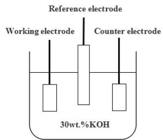
Int. J. Electrochem. Sci., Vol. 15, 2020                                                          5918

2. EXPERIMENT

2.1 Materials

       The spraying material used in this experiment is NiAl powder with a particle size of 3µm ~ 10µm.
The main composition (mass fraction) is 95% Ni, 5% Al, and its material composition table is listed in
Table 1. Figure 1 is a SEM image of the NiAl powder. It can be seen from the figure that the NiAl
powder has a regular spherical shape, and some granule with a size from 1µm to 3µm are attached to the
surface.

Table 1. NiAl spray material composition parameters

                 Ingredient Name             Ni (%)                       Al (%)
                 NiAl                        95                           5

                           Figure 1. 5000 times SEM image of NiAl powder

                       Figure 2. Macro surface morphology of a nickel substrate
Int. J. Electrochem. Sci., Vol. 15, 2020 5919
The base material is nickel foam with the size is 15mm × 20mm × 0.5mm. Figure 2 is a macro
morphology of a nickel substrate. From the figure, it can be found that the foamed nickel substrate is a
sponge-like porous material and is relatively rough. Figure 3 is an SEM image of a nickel substrate
enlarged about 50 times. The figure 3 shows that the foamed nickel exhibits a multi-layered hole
structure with a hole diameter size from 0.5 mm to 1.5 mm.
Figure 3. 50 times magnified SEM image of nickel substrate
2.2. Experimental setup
2.2.1 Atmospheric plasma spraying
Table 2. APS preparation process parameters for NiAl layer
Parameter Name Parameter Value
Ar/×10-3m3·min-1 30-60
H2/×10-3m3·min-1 5-25
Current/A 530-810
Voltage/V 50-80
Spraying distance/mm 90-130
Spray gun moving speed/mm·s−1 940-1200
Powder feed rate/×10-3m3·min-1 2-2.7
Figure 4. Schematic diagram of atmospheric plasma spray equipmentInt. J. Electrochem. Sci., Vol. 15, 2020 5920
Atmospheric plasma spray technology (APS) is to use a plasma arc as a heat source to heat the
target material to a molten state under high atmospheric conditions and hit the substrate at a high speed,
thereby forming a dense coating on the substrate to block oxygen [15-17]. NiAl powder was sprayed on
the foamed nickel substrate through the F6 plasma gun of APS (MF-P1000, GTV, Germany). The
coating process parameters are shown in Table 2. A schematic diagram of atmospheric plasma spraying
technology could be seen in FIG. 4.
2.2.2 electrolytic cell
The electrochemical test involved in this study used a three-electrode test system. As shown in
Figure 5, three electrodes (working electrode, reference electrode and counter electrode) should be
employed in electrolytic cell. The working electrode (WE) is the research and operation object of the
experiment. If the reduction reaction occurs on the electrode, it is the cathode, and the oxidation reaction
is the anode. Normally, the reference electrode (RE) could be a standard to measure another electrode
during the test [18].In this paper, Hg / HgO with a pH of 14 is used as a reference electrode, and the
current zero voltage is 0.098V (rel. SHE). This represents a reduction of 0.098V in the value measured
in this study compared to a standard hydrogen electrode. The counter electrode (CE) or the auxiliary
electrode uses the passing polarization current to realize the polarization of the counter electrode.
In this study, a three-electrode system was used for electrochemical measurement of hydrogen
electrode. The reference electrode, counter electrode and working electrode applied in test were Hg /
HgO, carbon rod and hydrogen electrode prepared by atmospheric plasma spraying, respectively. Take
an area of 3 cm2 at room temperature, and the electrolyte is a 30 wt.% KOH solution.
Figure 5. Schematic diagram of alkaline water electrolysis
2.3 Material and electrochemical characterization
X-ray diffractometer was used for phase analysis of NiAl coated. (XRD, Bruker D8 Advance)
The X-ray diffractometer scans at a speed of 2º/min over a diffraction angle range of 10º to 80º. The
scanning electron microscope (SEM, Quanta 200, FEI, Holland) was used to study the microstructure ofInt. J. Electrochem. Sci., Vol. 15, 2020 5921
NiAl coated. In addition, the potential range of the cyclic voltammetry test (CV) is set to -1.1 V ~ 0.6V,
and the scan rate is 10 mV / s. The chronoamperometry test (CA) has a transition potential of -1.1V and
a test time of 200 seconds. Linear scanning voltammetry (LSV) was collected at a scan rate of 10 mV /
s to obtain a polarization curve of potential and current. In this study, AC impedance spectroscopy (EIS)
was measured by the electrochemical workstation (DH7000, DONGHUA, China) with the frequency
from 100 KHz to 0.01 Hz.
3. RESULTS AND DISCUSSION
3.1 Microstructure of powder and coating
X-ray diffraction data of Ni substrate and NiAl powder are shown in Figs. 6 and 7. The figure 6
shows that at 2θ = 44.5 °, 51.8 °, and 76.4 °, the sharp diffraction peaks form a highly crystalline foamed
nickel phase [19]. In Figure 7 at 2θ = 43.9 °, 51 °, and 75.4 °, the phase of the NiAl coated is more
consistent with Ni4Al. According to Kovanda et al. [20], the XRD pattern of Ni2Al, Ni3Al, and Ni4Al
have obvious characteristic peaks at 76.4 °. In addition, during the plasma spraying process of the NiAl
coated, other substances such as NiAl, Ni3Al and the like were mixed in a high-temperature environment,
and thus a sharp superimposed resonance diffraction peak was formed at a position of 75.4 °.
Figure 6. XRD pattern of Ni substrate.Int. J. Electrochem. Sci., Vol. 15, 2020 5922
Figure 7. XRD pattern of NiAl coated.
As illustrated in figure 8, a SEM image of NiAl powder coated on a nickel substrate at a
magnification of 100 times, and figure 9 shows a SEM image of 500 times magnification. As can be
seen from the figure, the NiAl powder forms a dense protective layer on the nickel substrate, with a
rough surface and stacked layers. Koj et al. [21] also confirmed the effect of the thickness of the alloy
deposited on the electrode surface to OER during the experiment. Conclusion it is indicated that such a
protective layer can effectively protect the Ni-based foam electrode from the corrosion of alkaline KOH
aqueous solution, thereby prolonging the electrode life.
Figure 8. 100 times magnified SEM image of NiAl coated.
Figure 9. 500 times magnified SEM image of NiAl coated.
3.2 Evaluation of the electrochemical properties of the NiAl thin coating
3.2.1 LSV Analysis
For study the effect of the prepared coating on the hydrogen evolution performance of the
hydrogen electrode, the hydrogen evolution polarization curves of uncoated foam Ni electrode and NiAl
coated foam Ni electrode in 30wt.% KOH solution were tested, as shown in Figure 10 (a). It descripted
that the hydrogen evolution potential of the pure Ni electrode is -1.1V, and that of the NiAl-coated NiInt. J. Electrochem. Sci., Vol. 15, 2020 5923
electrode is -1.02V. The hydrogen evolution potential of NiAl coated has a significant positive shift
compared to the pure Ni electrode without coating, and the positive hydrogen shift potential is 0.08V.
After the test, the hydrogen evolution potential about Ni electrode and NiAl-coated Ni electrode are -
1.09V and -1.01V respectively with the current density of 0.2 mA cm-2.The greater the hydrogen
evolution polarization potential at the same hydrogen evolution current density, the more easily the
hydrogen evolution catalytic reaction occurs, indicating that the electrode with NiAl coated has higher
catalytic activity. Similarly, when the potential is -1.1V, the current density achieved by the NiAl-coated
electrode is 1.04 mA cm-2, which is much larger than the corresponding current density of the nickel
electrode 0.26mA cm-2. Within a certain range, the magnitude of the cathode hydrogen evolution current
density directly reflects the strength of the hydrogen evolution reaction rate. Zhang et al. [22] also
pointed out in the research that electrodeposition electrodes with larger current density show better
hydrogen evolution activity than pure nickel electrodes.The higher the current density, the stronger the
reaction, the more intense the reaction, and the faster the hydrogen evolution rate; otherwise, the weaker
the reaction, the more peaceful the reaction, and the slower the hydrogen evolution. This result indicates
that the electrode with NiAl coated can accelerate the hydrogen evolution reaction rate and has higher
electrochemical activity.
3.2.2 CA Analysis
To further test the electrocatalytic activity and hydrogen evolution stability of NiAl coated
electrode against hydrogen evolution in alkaline media, the chronoamperometry curves of Ni electrode
and NiAl coated electrode at -1.1V were tested, as shown in Figure 10 (b) Show. The potential stepped
to -1.1V, the chronoamperometry curve of the Ni electrode and NiAl coated electrode are very stable,
and it can maintain stable hydrogen evolution activity even after working in alkaline solution for a long
time.
3.2.3 CV Analysis
Figure 10 (c) is the cyclic voltammetry curve of Ni electrode and NiAl coated electrode in
30wt.% KOH solution, with a sweep speed of 10 mV / s. By comparison we can see that both curves
have typical redox peaks in KOH solution. In the figure, the oxidation peak of the Ni electrode appears
at about 0.362V, and the oxidation peak of the NiAl coated electrode appears at about 0.367V,
corresponding to the oxidation of OH- to O2. The reduction peak of the Ni electrode appeared at about
0.258V, and the reduction peak of the NiAl coated electrode appeared at about 0.26V, corresponding to
the reduction of H+ to H2. In addition to the basic redox peaks of NiAl coated electrode, other redox
peaks appeared at about -0.9V. It is speculated that some redox reactions of Al occurred in the NiAl
coated electrode. The hydrogen evolution reaction is an interface reaction. The rougher the electrode
surface, the greater the surface activity. Gabler et al. [23] found that the overpotential of the rough
surface electrode was significantly lower than that of a pure nickel electrode with a smooth surface
through CV curve.This makes the reduction of the activation energy in the hydrogen evolution reactionInt. J. Electrochem. Sci., Vol. 15, 2020 5924
more conducive to the progress of the hydrogen evolution reaction, and the hydrogen evolution
overpotential decreases.
3.2.4 EIS Analysis
The Nyquist curve is shown in Figure 10 (d). The high-frequency region of the Ni electrode is a
large semicircle dominated by charge-transfer, and the low-frequency region is a small semicircle
controlled by mass-transfer. The NiAl coated electrode appears as a semicircle dominated by charge-
transfer in the high-frequency region and as a straight line with a slope of 1 controlled by mass-transfer
in the low-frequency region. The figure shows that in the high frequency region, the diameter of the
semicircle fitted by the NiAl coated electrode is smaller than that of the Ni electrode, indicating that the
hydrogen evolution activity of the NiAl coated electrode is better than that of the Ni electrode.
Figure 10. Electrochemical test chart of Ni electrode and NiAl coated electrode in 30wt.% KOH
electrolyte. (a) Linear scanning voltammetry of two samples with a scan rate of 10 mV / s. (b)
Chronoamperometry curve of two samples at -1.1V transition potential. (c) Cyclic
voltammogram of two samples cycled between -1.1V and 0.7V with a scan rate of 10 mV / s .
(d) Electrochemical impedance spectrum of two samples.
4.CONCLUSIONS
In this study, NiAl alloy powder and foamed nickel were fused together by plasma spraying to
prepare a hydrogen electrode with NiAl alloy coating as the surface modification layer of the electrode.Int. J. Electrochem. Sci., Vol. 15, 2020 5925
By comparing the hydrogen evolution of the foamed nickel electrode and the NiAl coated electrode in
the electrolytic alkaline water experiment, the cathode hydrogen evolution overpotential was reduced
and the preparation of cathode materials with high catalytic activity was explored. The results show:
(1) Ni-based alkaline water hydrogen production electrodes with good catalytic activity can be
prepared by plasma spraying technology.
(2) Under the same hydrogen evolution current density of 0.2 mA cm-2, the hydrogen evolution
potential of the pure Ni electrode is -1.09V, and the hydrogen evolution potential of the electrode with
NiAl coated is -1.01V. The hydrogen evolution potential of the NiAl coated electrode was shifted by
0.08V, indicating that the electrode with NiAl coated had higher catalytic activity.
(3) CA test shows that the chronoamperometry curve of pure Ni electrode and NiAl coated
electrode is very stable, and it has stable hydrogen evolution activity when working in alkaline solution
for a long time.
(4) The EIS data show that the electrochemical resistance of the electrode with NiAl coated is
lower than that of the Ni electrode, and it shows good hydrogen evolution performance.
ACKNOWLEDGEMENTS
This work was supported by Fund Project of Guangxi Key Laboratory of Automobile Components and
Vehicle Technology, Guangxi University of Science and Technology (No.2017GKLACVTZZ04);
Innovation Project of GuangXi University of Science and Technology Graduate
Education(YCSW2019210,YCSW2020217);GDAS' Special Project of Science and Technology
Development(N0.2017GDAS CX-0202);Innovation Team Project of GuangXi University of Science
and Technology(No.3).Fund Project of the Key Lab of Guangdong for Modern Surface Engineering
Technology(No.2018KFKT01).
References
1. Wilhelm Kuckshinrichs, Jan Christian Koj, J. Clean. Prod., 203(2018)619.
2. Kai Zeng, Dongke Zhang, Prog. Energ. Combust., 36(2010)307.
3. Martín David, Carlos Ocampo-Martínez, Ricardo Sánchez-Peña, J. Enegry Storage, 23(2019)392.
4. Rami S. El-Emam, Hasan Özcan, J. Clean. Prod.,220(2019)593.
5. Ayfer Veziroglu, Rosario Macario, Int. J. Hydrogen Energ., 36(2011)25.
6. K. Priya, K. Sathishkumar, N. Rajasekar, Renew. Sust. Energ. Rev., 93(2018)121.
7. Fabian Fischer, Renew. Sust. Energ. Rev., 90(2018)16.
8. Guanyu Liu, Yuan Sheng, Joel W. Ager, Markus Kraft, Rong Xu, J. Energy. Chem.,
1(2019)100014.
9. Mukesh Kumar, Nagaraj P. Shetti, Mater. Sci. Tech-Lond., 1(2018)160.
10. Jaromír Hnát, Michaela Plevova, Ramato Ashu Tufa, Jan Zitka, Martin Paidar, Karel Bouzek, Int.
J. Hydrogen Energ., 44(2019)17493.
11. Evrim Baran, Zeynep Baz, Ramazan Esen, Birgül Yazici Devrim, Appl. Surf. Sci., 420(2017)416.
12. W. Fan, Y. Bai, Ceram. Int., 42(2016)14299.
13. Bo Huang, Chao Zhang, Ga Zhang, Hanlin Liao, Surf. Coat. Tech., 377(2019)124896.
14. Lech Pawlowski, Surf. Coat. Tech., 203(2009)2807.
15. Baoxia Ma, Jinyou Li, Results Phys., 15(2019)102550.
16. Ji-Eun Kim, Ki-Kwang Bae, Chu-Sik Park, Seong-Uk Jeong, Kyeong-Ho Baik, Jeong-Won Kim,
Kyoung-Soo Kang, Ki-Bong Lee, Young-Ho Kim, J. Ind. Eng. Chem., 70(2019)160.Int. J. Electrochem. Sci., Vol. 15, 2020 5926
17. M. Robotti, S. Dosta, M. Gardon, I.G. Cano, J.M. Guilemany, M. Kourasi, B. Mellor, R. Wills, J.
Enegry Storage, 5(2016)127.
18. Nur Lina Rashidah Mohd Rashid, Abdullah Abdul Samat, Abdul Azim Jais, Mahendra Rao
Somalu, Andanastuti Muchtar, Nurul Akidah Baharuddin, Wan Nor Roslam Wan Isahak, Ceram.
Int., 45(2019)6605.
19. Mehrshad Moshref Javadi, Hossein Edris, Mahdi Salehi, J. Mater. Sci. Technol., 27(2011)816.
20. František Kovanda, Tomáš Rojka, Petr Bezdička, Květa Jirátová, Lucie Obalová, Kateřina
Pacultová, Zdeněk Bastl, Tomáš Grygar, J. Solid State Chem., 182(2009)27.
21. Matthias Koj, Thomas Gimpel, Wolfgang Schade, Thomas Turek, Int. J. Hydrogen Energ.,
44(2019)12671.
22. Kaiyue Zhang, Wei Xiao, Junyao Li, Jianguo Liu, Chuanwei Yan, Electrochim. Acta,
228(2017)422.
© 2020 The Authors. Published by ESG (www.electrochemsci.org). This article is an open access
article distributed under the terms and conditions of the Creative Commons Attribution license
(http://creativecommons.org/licenses/by/4.0/).You can also read