A High-Speed Precision Bearing Internal Grinding Machine and Grinding Process
←
→
Page content transcription
If your browser does not render page correctly, please read the page content below
A High-Speed Precision Bearing Internal Grinding Machine and Grinding Process Zhou Chang ( starismyfriend@163.com ) Xi'an Jiaotong University Qian Jia Xi'an Jiaotong University Lai Hu Xi'an Jiaotong University Original Article Keywords: Grade P2 bearing, Internal grinding machine, hydrostatic pressure, high-speed, precise Posted Date: May 4th, 2021 DOI: https://doi.org/10.21203/rs.3.rs-423958/v1 License: This work is licensed under a Creative Commons Attribution 4.0 International License. Read Full License
A High-speed Precision Bearing Internal Grinding Machine and

 Grinding Process
 Zhou Changa* Qian jiab Lai huc
a.School of mechanical and electrical engineering, Lanzhou Jiaotong University, Lanzhou,
Gansu, P.R. China 730070
b.State Key Laboratory for Manufacturing System Engineering, Xi’an Jiaotong University,
 Xi’an, Shaanxi, P.R. China, 710054
c.State Key Laboratory for Manufacturing System Engineering, Xi’an Jiaotong University,
 Xi’an, Shaanxi, P.R. China, 710054
E-mail: starismyfriend@163.com

Abstract: In order to meet the requirement of grade P2 bearing grinding, we designed a high-speed
internal grinding machine used for bearing raceway and inner circle grinding. The machine adopts
T-type layout and 4-axis NC linkage. It is supported by hydrostatic pressure and driven directly by
torque motor. Besides, it is equipped with high-speed hydrostatic grinding wheel spindle of ELKA.
Our design includes hydrostatic workpiece shaft, hydrostatic turntable and hydrostatic guide rail.
The design of this machine can ensure the high-speed grinding process and research has good
engineering application value. Finally, the designed precision grinding machine is used to grind
the P2 bearing raceway with reasonable processing technology.
Keywords: Grade P2 bearing; Internal grinding machine; hydrostatic pressure; high-speed; precise

1 Introduction
 Bearing is an important basic component, its quality directly reflects the national industrial
level. At present, China's basic components still can not meet the needs of the main engine
matching, many kinds of bearings still need to be imported. It still has space to advance for the
accuracy and life of domestic bearings. Especially in high-speed and heavy-duty service
conditions, the accuracy and life of domestic bearings can not be guaranteed[1].
 Imported rolling bearings can achieve grade P2 accuracy, while it’s difficult for domestic
rolling bearings. In other words, with the current processing level of bearings in China, it is
impossible to process grade P2 rolling bearings in large quantities and efficiently. At present, our
country still imports rolling bearings in many industries, for example, our bearings used in
high-speed EMUs, still need to be imported. In particular, it should be pointed out that foreign
bearing manufacturers have blocked bearing technology, and the export of grade P2 high precision
rolling bearings is strictly limited[2-4].
 Grinding as an important processing method of bearing rings, its importance is self-evident
[5-6]
 . Bearing raceway is the working surface of bearing, its processing quality has an important
impact on the accuracy and lifetime of bearing. The surface quality of bearing raceway after
grinding is called surface integrity, which includes two aspects [7-9]. One refers to the geometric
accuracy of the bearing raceway, usually including roughness, waviness, roundness, raceway
sideswing, groove error and so on, and the other one refers to the physical characteristics of the
surface of the bearing raceway, usually including residual stress, hardness, metallographic
structure, grinding metamorphic layer and so on. Geometric accuracy of bearing raceway usually

affects bearing accuracy, and the surface physical characteristics of bearing raceway usually affect
bearing lifetime. At present, there is still a big gap between domestic bearings and imported
bearings in accuracy and lifetime.
 In order to make up for the shortcomings of domestic bearings, we should improve the
manufacturing technology and equipment of bearings. Grinding machine is an important
processing equipment for bearings, which requires our government to invest a lot of time and
money to improve the technical index of bearing grinding machine.
 At present, the leading foreign bearing grinder manufacturers mainly exist in Europe, Japan,
the United States and other western developed countries. Heald in the United States and TOYO in
Japan have advanced bearing grinder technology, besides, there are more bearing grinder
manufacturers in Europe, such as LIDKOPING, KMT in Swedish; NOVA, MECANDORA, Famir
in Italian; WEMA-GLAUCHAU in German; Berthiez in French and so on. The bearing grinder
manufactured by these manufacturers, which can process the outer ring, inner ring and end face of
the bearing, has a wide processing range, high processing efficiency and accuracy[10,11]. However,
many bearing grinders in China have problems of low processing efficiency and accuracy, which
need to be solved urgently.
2 Overall design objectives and technical indicators of LGID300
 In this paper, we designed a high-speed precision grinder LGID300 to grind grade P2 angular
contact ball bearing 7014. By the grinding machine and grinding technology, we want to achieve
the precision and lifetime of 7014: 3000 hours’ lifetime for ceramic ball bearings and 2000 hours’
lifetime for steel ball bearings. Part technical indicators of 7014 are shown in Table 1.
 Table 1 Part of technical indicators of grade P2 angular contact ball bearing 7014
bearing external diameter internal diameter width Channel/Raceway roughness
B7014 110mm 70mm 20mm 0.02μm

 Figure 1 Grade P2 angular contact ball bearing 7014
 From Table 1, we can see that the accuracy index of 7014 is high, and its roughness is only
0.02 μm. The bearing raceway needs ultra-precision machining after grinding, and its roughness
can reach 0.02 μm. Considering all accuracy indexes of grade P2 angular contact ball bearing, we
presented the technical indexes of ultra-precision internal grinding machine LGID300 as follows:
 (1) Machining accuracy: roundness: 0.3 μm; roughness: 0.3 μm.
 (2) Workpiece material: quenched bearing steel, hardness: ≤ HRC62.
 (3) Maximum size of workpiece: inner diameter: 200mm; width: 160 mm.
 (4) Location accuracy: resolution: 0.1μm; repetitive positioning accuracy: 0.5 μm; absolute
positioning accuracy: 3 μm.
 (5) X/Z axis travel: 250 mm; positioning accuracy: 1 μm; repetitive positioning accuracy: 0.3
μm; feed speed: 0.01-4.8 m/min; minimum feed: 20 nm; straightness: whole travel < 0.3 μm.
 (6) Turntable travel: ± 90 degrees; positioning accuracy: 2.5 arc seconds; repetitive
positioning accuracy: 1 arc second; rotational speed: 0.01-10 rpm.
 (7) Workpiece shaft: hydrostatic spindle, 1500 rpm; rotation error < 0.3 μm.
 (8) Grinding wheel axle: maximum speed is 50000 rpm; rotation error is less than 0.3μm.
 (9) Grinding wheel dresser: repetitive positioning accuracy: 1 μm.
3 Overall structure scheme of LGID300
3.1 Grinding scheme and grinding wheel dressing scheme
 The machining method of inner raceway of outer ring is cut-in grinding, which can also be
called profiling grinding. The grinding wheel is dressed by rotary dressing tool. The material of
grinding wheel is CBN and the binder is ceramics. When we grind the inner raceway, we use
grinding wheel dresser to dress the formed grinding wheel, which requires the workpiece spindle,
grinding wheel spindle and turntable feed by interpolation method. When we grind the inner ring
of bearing, the machine only needs the workpiece spindle and grinding wheel spindle feed by
interpolation method, and does not need the rotation interpolation of turntable.
 In order to make full use of the rotational accuracy of the hydrostatic workpiece axis, we
made the grinding wheel dresser coaxial with the workpiece axis when we designed the grinding
wheel dresser of LGID300. In this way, we guarantee the dressing accuracy and reduce the wear
of grinding wheel, besides, the motor and feed motion of the dresser are omitted, so we can save
the cost and improved the dressing accuracy at the same time.
3.2 Overall unit layout of LGID300
 Considering the accuracy of ultra-precision machine tools, we usually use the multi-axis
arrangement with less coupling or uncoupling, and adopt the structure of small Abbe error as far
as possible, so that the machine structure can achieve high stiffness and stability. The common
structural layout of ultra-precision machine includes overlapping, R-θ, turntable and T-type. These
layouts are suitable for different processing requirements, each having its own advantages and
disadvantages [12].
 In the design of LGID300, the maximum diameter of the workpiece is 230 mm, and the width
is 160 mm. It is not big so LGID300 belongs to small and medium-sized machine. According to
the above reasons, LGID300 adopts T-type layout, which is conducive to improve the rigidity of
machine, strengthen the bearing capacity of guideways, and guarantee the processing accuracy.
 Internal grinding design scheme: fixture clamped on workpiece axle doing circular motion;
CBN grinding wheel on grinding wheel axle doing circular motion at the same time; workpiece
axle worktable driving workpiece axle along X direction to do linear feed motion; grinding wheel
axle worktable driving grinding wheel axle along Z direction to do linear feed motion.
 Internal grinding requires the center axis of grinding wheel axis to be equal to that of
workpiece axis. We designed a heightening pad to make the two center axes equal. Because Z axis
linear motion is similar to X axis linear motion, we use the same structure design, that is,
hydrostatic guide rail and ball screw to complete linear feed.
 In the design of LGID300, we designed turntable to dress the grinding wheel and mounted
the turntable on the Z-axis worktable. We also refined the mechanical structure considering the
assembly and operation of LGID300.
3.3 Whole machine design of LGID300
 Driving mode: Frame-less torque motor drives the mechanical structure directly. In the linear

feed axis, the torque motor drives the lead screw directly. In the rotary feed axis, the torque motor
drives the rotor directly.
 Support mode: LGID300 has linear motion in directions of XZ and rotary motion of
workpiece spindle and turntable. Adopting hydrostatic support, we can obtain better motion
accuracy and rigidity. So we used hydrostatic guideways in XZ directions and hydrostatic bearings
in workpiece spindle and turntable.
 Precision spindle: We use hydrostatic spindle on grinding wheel spindle and workpiece
spindle. The grinding wheel spindle is purchased and the workpiece spindle is self-made. Grinding
wheel spindle adopts 50,000 RPM high precision hydrostatic spindle produced by ELKA
Precision Company. The hydrostatic spindle has high rotational speed, high rotational accuracy
and good thermal stability, and it is suitable for bearing precision grinding. The main technical
data of the motorized spindle are: speed range: 10000-50000 RPMs; built-in permanent magnet
motor; maximum sustained power: 8KW; no feedback; tool clamping interface: 17mm/M16;
radial motion error under all rotating speeds < 0.06 μm; axial motion error under all rotating
speeds < 0.12 μm; axial stiffness: 69 N/μm; axial load capacity: 550N; radial stiffness: 35 N/μm;
radial load capacity: 400N. Figure 2 shows the profile size of ELKA hydrostatic grinding
motorized spindle.

 Figure 2 Profile size of ELKA hydrostatic internal grinding spindle
 Overall design: Through the analysis of grinding process, we selected the reasonable layout
of the whole machine, driving mode, support mode and motorized spindle, obtained the overall
design results of LGID300. Specific parameters are shown in Table 2.
 Table 2 Main specification parameters of LGID300
 Structure type T-type layout and four-axis NC linkage
 Outline size 2200mm ×1700mm ×1950mm
 Inner raceway of bearing outer ring and inner
 circle of inner ring, etc.
 Processing object and scope
 Workpiece diameter≤Φ230mm, Workpiece
 width≤160mm
 Torque motor + precision ball screw +
 Servo feed Driving mode
 hydrostatic guide rail
 system
 Axial travel X axis: 250mm、Z axis: 250mm
 Rotary table C Oil static pressure precision turntable, travel±90°

Workpiece axis B Oil static pressure spindle, 2000r/min
 Grinding wheel spindle Oil static pressure, maximum speed 50000r/min

 Figure 3 Overall design view of LGID300
4 Servo drive system design
4.1 Screw selection
 We selected the precision ball screw produced by THK in Japan. Considering the cost, we
chose the grade C3 accuracy. Considering the use space, we chose the DIK nuts and select the
fixed installation mode at both ends. We used pre-stretching method to assemble the screw and
selected angular contact ball bearings produced by German FAG.
 According to the design index of linear feed motion axis and THK manual, we selected and
calculated the guide, diameter, total length and thread length of the lead screw, and completed the
stiffness check. The helical pitch of the lead screw is 5 mm, the diameter is 32 mm, the total
length of the lead screw is 852 mm and the thread length is 590 mm. By choosing and designing
the screw, we made it meet the requirement of 250mm linear travel of X-axis and Z-axis.
4.2 Selection of torque motor and servo driver
 The friction coefficient of hydrostatic guideway is very small, which is 0.0005. The
acceleration design index of two linear axes of LGID300 is 0.5g. In the process of acceleration
and deceleration, the driving moment of the motor is mainly to overcome the inertia moment.
The rated speed of the torque motor is 3800 r/min, and the continuous stall torque is 4.90Nm. It
can meet the requirements of acceleration, speed and drive of the X and Z axes in the technical
specifications.
 We select the KBMS series frameless brushless motor of Kollmorgen in USA as servo driver
to cooperate with AKD servo driver.
4.3 Design of detection feedback system
 We use angle encoder to control the speed loop. We select the circular grating of British
RENIWHAW. The maximum speed of the grating is 2680r/min and the system accuracy is 2.97
arc seconds. After subdivision by 200 times sub divider, the system can meet the requirements of
positioning accuracy, repetitive positioning accuracy, feed speed and minimum feed rate for X and
Z linear feed axes.
 We use linear grating ruler to control the position loop. We select the grating ruler of
HEIDENHAIN Company in Germany, which is an open grating ruler with high precision and low
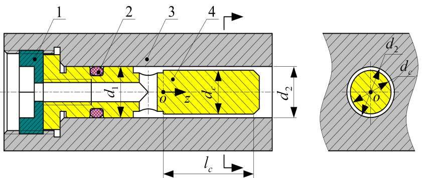
price. It is suitable for bearing grinding. The total length of the grating ruler is 270 mm, which meets the requirement of 250 mm linear travel of X axis and Z axis. The signal period of the linear grating is 0.512 um, and the subdivision of the sub divider is 100 times. When the A and B signals are frequency doubled 4 times in the numerical control system, the positioning resolution of the axis can reach 1.28 nm, which can meet the requirements of the positioning accuracy and the repetitive positioning accuracy of the X and Z linear feed axes. For feed speed, circular grating and linear grating can also meet the requirements. 4.4 Results of servo drive system design In our design, the servo feed mechanism of X axis and Z axis uses the moment motor to drive the lead screw directly through the expansion sleeve. We installed circular grating at the end of the lead screw, and equipped the worktable with linear grating, and we realized the double closed-loop control of the position and speed loop for the feed system, so as to achieve the nano-resolution and sub-micron positioning accuracy of the linear motion axis. 5 Design of hydrostatic guide rail 5.1 Choice of guide form and throttle There are two types of hydrostatic guideways, open and closed. The closed hydrostatic guide has better rigidity than the open. There are two modes of oil supply: quantitative mode and constant pressure mode. The cost of constant pressure oil supply is lower. Combining the above two aspects, we selected the liquid closed hydrostatic guide, and the constant pressure oil supply mode. We use a new type of annular slot throttle in hydrostatic guide rail and hydrostatic bearing of LGID300 [13]. Its effective throttle size is annular width dc and annular length lc. The structure of annular throttle is shown in Fig. 4, in which the 1-indenter is used to fix the throttle and the 2-'O' shaped sealing ring is used to prevent the oil backflow. Figure 4 Structure diagram of annular slot throttle 5.2 Bearing capacity and oil film stiffness The total gravity of all parts of X and Z linear feed axle guide is about 3000N and 3300N respectively. The vertical static stiffness of the hydrostatic guide is about 7000N/um, and the horizontal static stiffness is about 5000N/um by calculation. Bearing capacity and oil film stiffness can meet the design requirements. 5.3 Guideway accuracy and oil film thickness The two relative moving surfaces of the hydrostatic guideway are in pure liquid friction state, and the oil film stiffness is large, which raise the requirements of the guideway geometric accuracy [14]. Usually need: 1 1 ( ~ ) h0 2 3 Formula: ∆- Total error of geometric accuracy in the surface of the guide rail; ℎ0 - Oil film
thickness of the guide rail
 The oil film thickness of the guide rail should not be too large, so as to avoid reducing the
rigidity of the guide rail, and should not be too small also. Generally, the following values are
recommended for the design of hydrostatic guideways: the oil film thickness of hydrostatic
guideways for medium and small machine tools ℎ0 = 15 − 30 , and the oil film thickness of
hydrostatic guideways for large machine tools ℎ0 = 30 − 60 . We adopts ℎ0 = 20 .
5.4 Design results of guide rail structure
 In order to make the oil film uniform, we designed two oil chambers. The hydrostatic guide is
composed of the left and right guide bars and the slide saddle. The sliders move with the
workbench together. We make the oil circuit and the oil-saving hole on the moving sliders. After
all aspects calculating and optimizing of oil film dimension chain D1-D2, D3-D4, D6-D5, we
designed the dimension of guide as B=40mm, b=15mm, L=245mm, l=20mm, h=20μm.

 Figure 5 Structural design model of guide rail
6 Design of hydrostatic rotary parts
6.1 General design of hydrostatic bearing
 We adopt the overall design scheme of direct torque motor driving, hydrostatic bearing
supporting, non-contact circular grating feedback and computer digital control for the hydrostatic
turntable and spindle.
 Table 3 Design indexes of hydrostatic bearing
 Items Hydrostatic turntable Hydrostatic spindle
 Radial motion error 0.3 μm 0.3 μm
 Axial motion error 0.3 μm 0.3 μm
 Positioning accuracy 2.5 arc seconds 2.5 arc seconds
 Repetitive positioning accuracy 1 arc second 1 arc second
 Radial stiffness 2000 N/μm 1000 N/μm
 Axial stiffness 2000 N/μm 1000 N/μm
 Design speed 100 r/min 1500 r/min
6.2 Structural design of hydrostatic bearing
 Hydrostatic bearings include two parts: radial hydrostatic bearings and bidirectional thrust
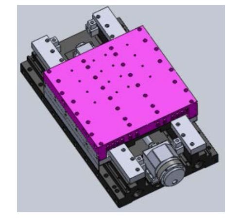
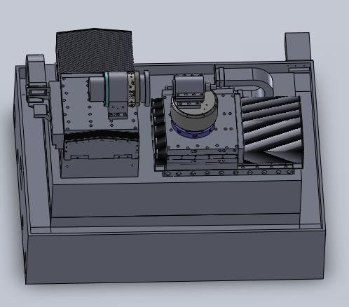
hydrostatic bearings. Radial hydrostatic bearings mainly bear radial loads, and bi-directional thrust
hydrostatic bearings mainly bear axial loads. We adopt the structure of "axle wrap bearing bush"
to improve the axial stiffness of the rotating spindle. The hydrostatic bearings use the same throttle
as the hydrostatic guide.
6.3 Torque motor and grating ruler
 The type of the torque motor of hydrostatic turntable is KBMS-57×01-A. The type of the
torque motor of hydrostatic spindle is KBMS-43×03-A. The parameters of the torque motors is
shown in Table 4.
 Table 4 Technical parameters of torque motor
 Items KBMS-43×03-A KBMS-57×01-A
 Rated power 2.52 kW 2.31 KW
 Rated torque 21 N.m 18.8 N.m
 Rated speed 1500 r/min 2050 r/min
 Rotor inner diameter 76.28 mm 104.17 mm
 Rotor outer diameter 159.28 mm 202.90 mm
 We select Renishaw's non-contact circular grating for both hydrostatic turntable and spindle.
Its nominal inner diameter is 80 mm, outer diameter is 100 mm, and the number of its dividing
lines is 15744. With 200 times sub divider, its resolution can reach 0.41 arc second. Because the
motion of hydrostatic bearing is smooth and it has no creeping phenomenon at low speed, we can
guarantee the positioning accuracy of 2.5 μm and repetitive positioning accuracy of 1 μm by the
control of actuator.

 Figure 6 Three-dimensional model of oil hydrostatic turntable

 Figure 7 Three-dimensional model of oil hydrostatic spindle
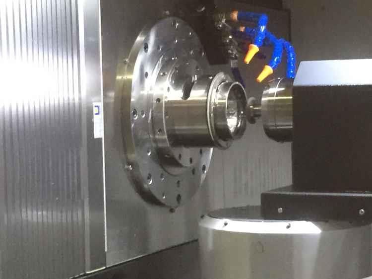
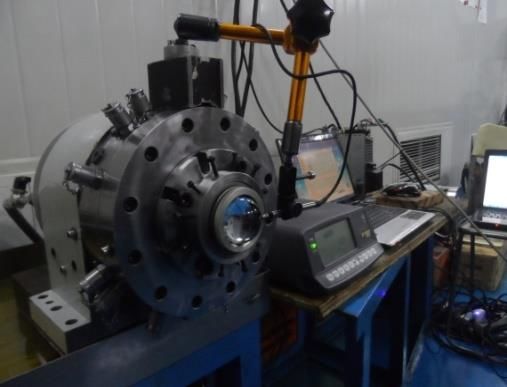
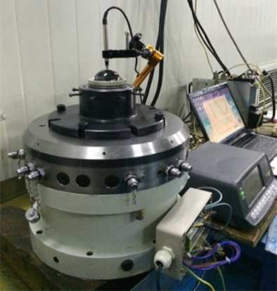
7 Accuracy detection

 Figure 8 Rotation accuracy detection process

 Figure 9 Rotation accuracy detection process
 We measured the radial and axial runout errors of the hydrostatic turntable at constant
temperature of 20 ±2℃. The radial and axial runout of the hydrostatic turntable are 0.31 μm and
0.28 μm respectively. The radial and axial runout of the hydrostatic spindle are 0.32 μm and 0.28
μm respectively.
8 grinding test

 Figure 10 Grinding process
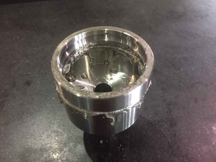
Figure 11 Grinding process
 Bonding fixture
 Figure 10 and figure 11 show the grinding bearing raceway, and the grinding process is
reliable and effective. The use of adhesive fixture is a major feature of this study.

 Figure 12 shows micrographs of the affected layers
 0.40

 0.35

 0.30
 Roughness /μm

 0.25

 0.20

 0.15

 1 2 3 4 5 6 7 8 9
 Number of test group

 Figure 13 Roughness
 With the increase of grinding wheel speed, the grinding roughness decreases to 0.1μm,P2
level bearing raceway roughness grinding is reasonable. The use of grinding fluid is also less,
which meets the requirements of green manufacturing
8 Conclusion
1. To meet the requirement of grade P2 bearing grinding, we designed a high-speed internal
grinding machine for bearing raceway and inner circle grinding. The line speed of grinding can
reach 120 m/s.
2. We designed the hydrostatic guide with the positioning accuracy of 1 μm, the repetitive
positioning accuracy of 0.3 μm and the straightness of 0.3 μm.
3. We designed the hydrostatic turntable and hydrostatic spindle. Their radial and axial runout are
both 0.3 μm.
4. The machine has high processing accuracy. Its roundness is 0.3 μm, roughness is 0.3 μm.
5. The machining accuracy meets the requirements of P2 raceway.

Declarations

Availability of data and materials
The availability of data and materials is real and valid.

Competing interests
No competing interest.

Funding
Funding from the Lanzhou Jiaotong University Foundation is gratefully acknowledged.

Authors' contributions
Zhou Chang conceived of the study, designed the study and collected the data. All authors
analysed the data and were involved in writing the manuscript.

Acknowledgments
The authors wish to acknowledge Dr Chen, professor of Xi’an Jiaotong University, for his help in
interpreting the significance of the results of this study.

9 Reference
[1] Pang G, Qi X, Ma Q, et al. Surface roughness and roundness of bearing raceway machined
 by floating abrasive polishing and their effects on bearing’s running noise[J]. Chinese
 Journal of Mechanical Engineering, 2014, 27(3): 543-550.
[2] Tao B, Xu W, Pang G, et al. Prediction of bearing raceways superfinishing based on least
 squares support vector machines[C]. Natural Computation, 2008. ICNC'08. Fourth
 International Conference on, 2008: 125-129.
[3] Wu M, Gao H. Experimental study on large size bearing ring raceways’ precision polishing
 with abrasive flowing machine (AFM) method[J]. The International Journal of Advanced
 Manufacturing Technology, 2016, 83(9-12): 1927-1935.
[4] Wu M, Ren C, Zhang K. ELID groove grinding of ball-bearing raceway and the accuracy
 durability of the grinding wheel[J]. The International Journal of Advanced Manufacturing
 Technology, 2015, 79(9-12): 1721-1731.
[5] Chen X, Rowe W, Mccormack D. Analysis of the transitional temperature for tensile residual
 stress in grinding[J]. Journal of Materials Processing Technology, 2000, 107(1-3): 216-221.
[6] Fergani O, Shao Y, Lazoglu I, et al. Temperature effects on grinding residual stress[J].
 Procedia CIRP, 2014, 14: 2-6.
[7] Kruszyński B W, Wójcik R. Residual stress in grinding[J]. Journal of Materials Processing
 Technology, 2001, 109(3): 254-257.
[8] Mahdi M, Zhang L. Applied mechanics in grinding. Part 7: residual stresses induced by the
 full coupling of mechanical deformation, thermal deformation and phase transformation[J].
International Journal of Machine Tools and Manufacture, 1999, 39(8): 1285-1298.
[9] Paul S, Chattopadhyay A. Effects of cryogenic cooling by liquid nitrogen jet on forces,
 temperature and surface residual stresses in grinding steels[J]. Cryogenics, 1995, 35(8):
 515-523.
[10] Agarwal, Sanjay, Rao, et al. Predictive modeling of force and power based on a new
 analytical;undeformed chip thickness model in ceramic grinding[J]. International Journal of
 Machine Tools & Manufacture, 2013, 65(2): 68-78.
[11] Asano K. Recent development in numerical analysis of rolling bearings basic technology
 series of bearings[J]. Koyo Engineering Journal, 2002, 160: 65-70.
Figures

Figure 1

Grade P2 angular contact ball bearing 7014

Figure 2

Pro le size of ELKA hydrostatic internal grinding spindle
Figure 3

Overall design view of LGID300

Figure 4

Structure diagram of annular slot throttle
Figure 5

Structural design model of guide rail

Figure 6

Three-dimensional model of oil hydrostatic turntable
Figure 7

Three-dimensional model of oil hydrostatic spindle

Figure 8

Rotation accuracy detection process
Figure 9

Rotation accuracy detection process
Figure 10

Grinding process
Figure 11

Grinding process Bonding xture
Figure 12

shows micrographs of the affected layers
Figure 13

Roughness
You can also read